Article

Angle Multiplexing Optical Image Encryption in the Fresnel Transform Domain Using Phase-Only Computer-Generated Hologram

1
Photonics and Information Lab, Department of Electrical Engineering, National Yunlin University of Science and Technology, Douliu Yunlin 64002, Taiwan
2
Graduate Institute of Color and Illumination Technology, National Taiwan University of Science and Technology, Taipei 10607, Taiwan
*
Author to whom correspondence should be addressed.
Photonics 2020, 7(1), 1; https://doi.org/10.3390/photonics7010001
Submission received: 12 November 2019 / Revised: 12 December 2019 / Accepted: 17 December 2019 / Published: 18 December 2019
(This article belongs to the Section Optical Communication and Network)

Abstract

:
We propose an angle multiplexing method for optics-based image encryption using a phase-only computer-generated hologram (POCGH) in the tilted Fresnel transform (TFrT) domain. Modified Gerchberg-Saxton algorithms, based on the three types of rotation manipulation in both the hologram and reconstruction planes, are used with their corresponding TFrT parameters to extract the phase-only functions (POFs) of the target images. All the extracted POFs are then phase-modulated and summed to obtain the final POCGH, which is capable of multiplexing and avoiding overlap in the reconstructed images. The computer simulation results show that the images corresponding to the various rotation manipulations at the hologram and image reconstruction planes can be successfully restored with high correlation coefficients. Due to the encrypted nature of the multiplexed images, a higher system security level can be achieved, as the images can only be correctly displayed when all the required parameters in the TFrT are available. The angle sensitivity on the image quality for each manipulation is also investigated.

1. Introduction

Optical security has received great attention and seen dramatic development since the last century due to the inherent diversity of optical signals and the high precision requirements of optical devices/architectures, which can significantly enhance system security levels [1]. Among the various types of applications, image encryption is very advantageous because of the parallel-processing capabilities of optics. Javidi first proposed a double-random-phase encoding (DRPE) method to encrypt an image into a noise-like complex signal [2]. Thereafter, optics-based encryption methods utilizing on Fourier, fractional Fourier, or Fresnel transforms (FrT) with various optical architectures have been aggressively developed for image encryption and verification uses [2,3,4,5,6,7,8,9,10,11]. The optical architecture for performing the FrT is the simplest, because no lenses are required. An image can be encrypted as a phase-only function (POF) and then reconstructed by determining the diffraction field at the reconstruction plane with the FrT. The POF can be determined by using the Gerchberg-Saxton algorithm (GSA) [12], and can serve as a type of phase-only computer-generated hologram (POCGH).
Conventional GSAs consider both the POF and image reconstruction planes with the coordinates (x0,y0) and (x,y), respectively, as being perpendicular to the optical axis. Therefore, the distance z0 between the two planes is fixed. A coherent light source (plane wave) of wavelength λ illuminates the POF h(x0,y0) and the amplitude of the diffraction field approximates the target image. In determining the diffraction field g(x,y), the FrT is used, and can be expressed as Equation (1) [13]:
g ( x , y ) = e j k z j λ z 0 e j k 2 z 0 ( x 2 + y 2 ) × h ( x 0 , y 0 ) e j k 2 z 0 ( x 0 2 + y 0 2 ) e j k z ( x 0 x + y 0 y ) d x 0 d y 0 ,
where k = 2 π λ denotes the wave number. In many practical applications, the POF and image reconstruction planes may require a higher degree of freedom. In other words, tilted planes are possible in designing optical image reconstruction systems. Leseberg and Frère proposed a method for generating a computer-generated hologram (CGH) of tilted planar objects based on the FrT [14]. Tommasi and Bianco evaluated the relationship between the rotated planes using the corresponding angular spectra of scalar diffraction fields [15]. In addition to the rotation, the angular spectra of the shifted CGH planes are also considered [16]. Matsushima et al. proposed a fast calculation method for the optical diffraction on the tilted planes based on the angular spectra of plane waves [17]. A method for numerically reconstructing CGHs on tilted planes was proposed to reconstruct the object field on the tilted planes [18]. Jeong and Hong presented an effective method for image reconstruction on arbitrarily-tilted planes with CGHs [19]. A technique for calculating the diffraction field from the tilted and shifted source plane was reported in [20].
Chang et al. proposed a method by which to compute the POCGH, which can project a holographic image onto tilted planes using fractional Fourier transformation [21]. A method for the diffraction calculation between the tilted planes with variable sampling rates on the Fourier spectrum was proposed to release the sampling restriction problem of the fast Fourier transform in the conventional method [22]. To accelerate the calculation of a CGH for a three-dimensional (3-D) object with a deep structure, Arai et al. proposed two improved wavefront recording plane (WRP) methods using nonparallel (tilted) WRPs [23]. Xiao et al. proposed an effective and accurate nonuniform fast Fourier transform algorithm to deal with diffraction propagation between the tilted planes [24]. Since the computation of diffraction fields between two nonparallel planes is more burdensome than that between two parallel ones, Stock et al. proposed a quasi-fast algorithm based on an Euler decomposition of the general rotation of tilted planes to solve this problem [25]. Their algorithm does not rely on the Fresnel approximation, and is not limited to small angles. The scale of output field can be adjusted as well. Recently, Vilardy et al. proposed an image encryption method which uses tilted planes in the Fourier and output planes in the double random phase encoding technique [26]. The angles of two tilted planes can serve as the additional security keys.
The authors have undertaken comprehensive studies of both the position and wavelength multiplexing methods with single or double POFs for image reconstruction [27,28,29,30,31,32,33]. In addition, there was an initial idea for angle multiplexing [34], along with a study on the effects of the rotation angle arrangements [35]. To extend these ideas, this paper considers three types of angle manipulation in the proposed image multiplexing method: (1) Angle multiplexing at only the image reconstruction plane; (2) Angle multiplexing at only the POCGH plane; (3) Angle multiplexing at both the reconstruction and POCGH planes.
The angle multiplexing scheme in the proposed method is quite different from previous schemes [28]. Firstly, regarding the multiplexing aspects, the tilted angles in the reconstruction and POCGH planes and the positions for various target images are different. Secondly, the proposed method uses only a single piece of phase information (the POCGH), rather than the double phase encoding system which is used in the aforementioned paper. Third, the reconstructed images are located at the same reconstruction plane in the proposed method, while the image is decrypted on different planes in the position multiplexing method.
The remainder of this paper is structured as follows. Section 2 provides the preliminaries of the diffraction theories required in the proposed method. The proposed angle multiplexing method is given in Section 3. In Section 4, we perform a computer simulation and observe that the results verify the effectiveness of the proposed system. Section 5 presents the conclusions.

2. Preliminaries

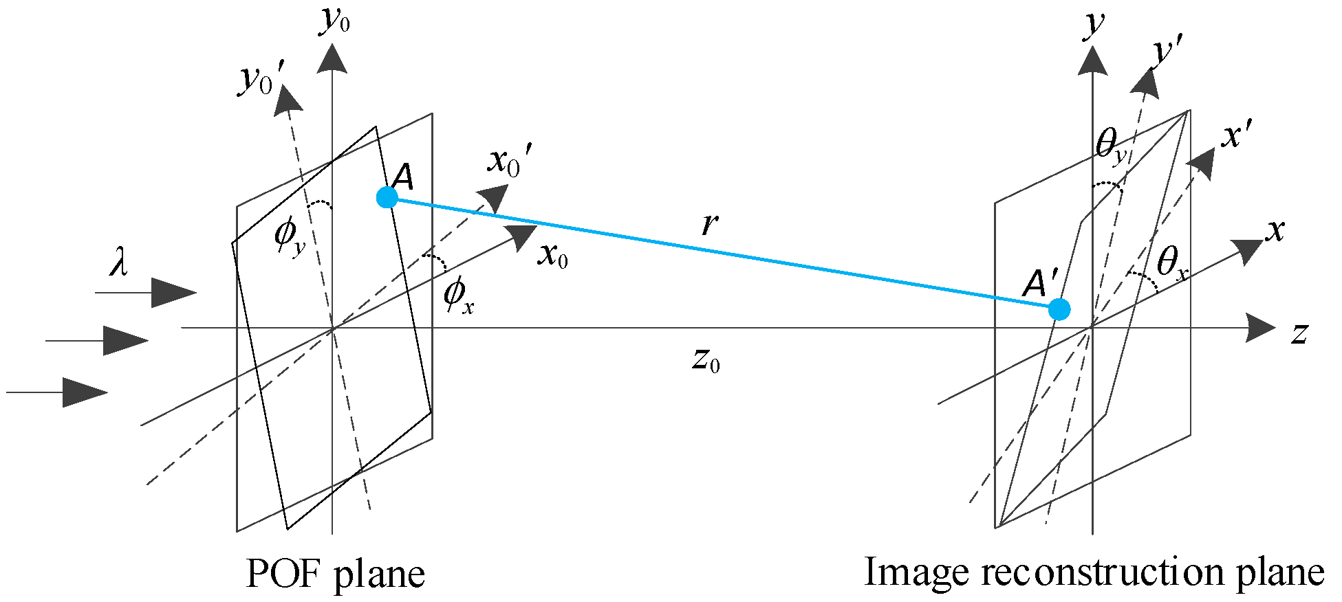
Figure 1 shows the generalized optical diffraction architecture when using a POF for single image reconstruction. (x0,y0) and (x,y) denote the original coordinates of the input POF and the output image reconstruction planes, respectively; z0 is the distance between the two origins at the two planes; ( x 0 ,   y 0 ) and (x′, y′) denote the coordinates of the rotated POF and image reconstruction planes, respectively. The rotation angles of the tilted POF and image reconstruction planes are denoted as ( ϕ x, ϕ y) and (θx, θy), respectively.
If we treat the rotation based on an axis as the coordinate transformation, the rotation order about the two axes is critical. That is, the combinational rotation matrices are different when using the different rotation orders on the Euler angles. In our case, we consider both the rotations about the “original” x- and y-directions. That is, the second rotation is not based on the first rotated axes. Therefore, the rotation effects about the two axes are independent and can be additive. In our rotation manipulation shown in Figure 1, the matrices denoting the rotations tilted about the original x′ and y′ directions can be expressed, respectively, as r x = [ cos θ x 0 0 0 1 0 sin θ x 0 1 ]   and r y = [ 1 0 0 0 cos θ y 0 0 sin θ y 1 ] . In addition, it is easy to prove that
r x r y   =   r y r x   =   [ cos θ x 0 0 0 cos θ y 0 sin θ x sin θ y 1 ] .
where r denotes the distance between two arbitrary points A and A at the rotated POF and reconstruction planes, respectively. Equation (3) shows how to determine this distance.
r = [ ( x 0 cos ϕ x x cos θ x ) 2 + ( y 0 cos ϕ y y cos θ y ) 2          + ( z 0 + x 0 sin ϕ x + y 0 sin ϕ y x sin θ x y sin θ y ) 2 ] 1 / 2
According to the Huygen-Fresnel principle [6], the light distribution g ( x , y )   on the rotated reconstruction plane, when the POF plane is also rotated, can be determined from the Fresnel diffraction of the POF h ( x 0 ,   y 0 ) . Let r x = x 0 cos ϕ x x cos θ x , r y = y 0 cos ϕ y y cos θ y , and r z = z 0 + x 0 sin ϕ x + y 0 sin ϕ y x sin θ x y sin θ y . By using the binomial approximation and parameters set out in the general optical architecture of the FrT, Equation (4) shows a generalized tilted Fresnel transform (TFrT) formula that describes the relationship between the two light fields f ( x , y ) and h ( x 0 ,   y 0 ) :
f ( x , y ) = 1 j λ h ( x 0 , y 0 ) exp ( j k r ) r z r 2 d x 0 d y 0 1 j λ h ( x 0 , y 0 ) exp ( j k r z ) r exp [ j k 2 r z ( r x 2 + r y 2 ) ] d x 0 d y 0 = exp [ j k ( z 0     x sin θ x     y sin θ y ) ] j λ h ( x 0 , y 0 ) × exp [ j k ( ( x 0 sin ϕ x   +   y 0 sin ϕ y ) ] r exp [ j k 2 r z ( r x 2 + r y 2 ) ] d x 0 d y 0 .
Assume r z r x ,   r z r y , and z 0 x 0 sin ϕ x + y 0 sin ϕ y x sin θ x y sin θ y . Then r z 0 . Equation (4) can be approximated as
f ( x , y ) 1 j λ z 0 exp [ j k ( z 0 x sin θ x y sin θ y ) ] × exp [ j k 2 z 0 ( x 2 cos 2 θ x + y 2 cos 2 θ y ) ] × h ( x 0 , y 0 ) exp [ j k ( x 0 sin ϕ x + y 0 sin ϕ y ) ] × exp [ j k 2 z 0 ( x 0 2 cos 2 ϕ x + y 0 2 cos 2 ϕ y ) ]      × exp [ j k z 0 ( x x 0 cos θ x cos ϕ x + y y 0 cos θ y cos ϕ y ) ] d x 0 d y 0 .
For image reconstruction purposes, we identify the target image as the magnitude | f ( x , y ) | 2   of the diffraction field. To simultaneously manipulate multiple images, various methods have been proposed; for example, multiplexing schemes based on selecting different wavelengths and reconstructing images at different diffraction distances [27,28,29,30,31,32,33]. In addition to the wavelength and position parameters in the FrT of a POF, an image can be reconstructed on a tilted plane with angles of rotations about the x and/or y axes [20]. This paper proposes a generalized angle-multiplexing method for multiple image encryption based on the TFrT with a POCGH composed of multiple POFs. By cooperating with the phase modulation method [29], each image can be reconstructed at a specific location with the given rotation angles at the POCGH and/or reconstruction planes. This paper assumes that the sizes of the POCGH and reconstruction images are fixed and equal during the simulation. The scaling due to the reduced projected size and pixilation effects caused by the rotation is not considered.

3. Proposed Method

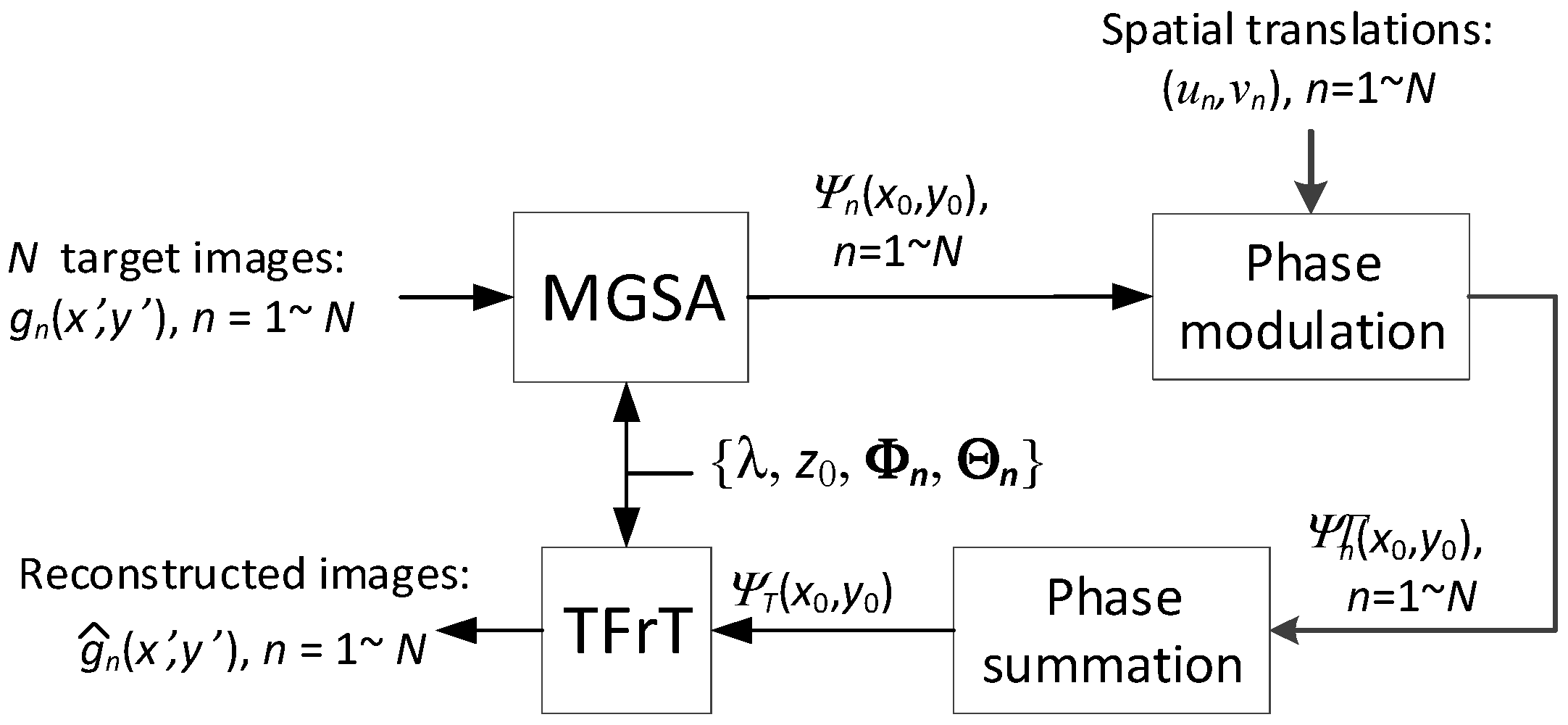
Figure 2 shows a flowchart of the generalized optical image multiplexing method. Given N target images, {gn, n = 1, …, N}, and their corresponding rotation angles, Θ n = { θ x n ,   θ y n } and Φ n = { ϕ x n ,   ϕ y n } , then θ x n , θ y n , ϕ x n , and ϕ y n denote the angles of the rotation about the x ,   y ,   x 0 , and y 0 axes, respectively, for the nth image at the reconstruction plane. The POF, Ψ n ( x 0 ,   y 0 ) , for each image can be retrieved by using the modified GSA (MGSA) [29] with the given parameters, including the distance z0, wavelength λ, and rotation angles { θ x n , θ y n , ϕ x n , ϕ y n } in the TFrTs. For multiplexing purposes, each POF is multiplied by a phase term, in which the corresponding spatial translation ( u n , v n ) is then defined. Next, all the POFs are summed and denoted as Ψ T ( x 0 ,   y 0 ) , which is the POCGH, and can be displayed in a phase-only device. To correctly reconstruct a specific target image, gn, the corresponding angle parameters { θ x n , θ y n , ϕ x n , ϕ y n } should be provided in the TFrT. Various parameter combinations can be adopted in the MGSA for multiplexing and encryption purposes.

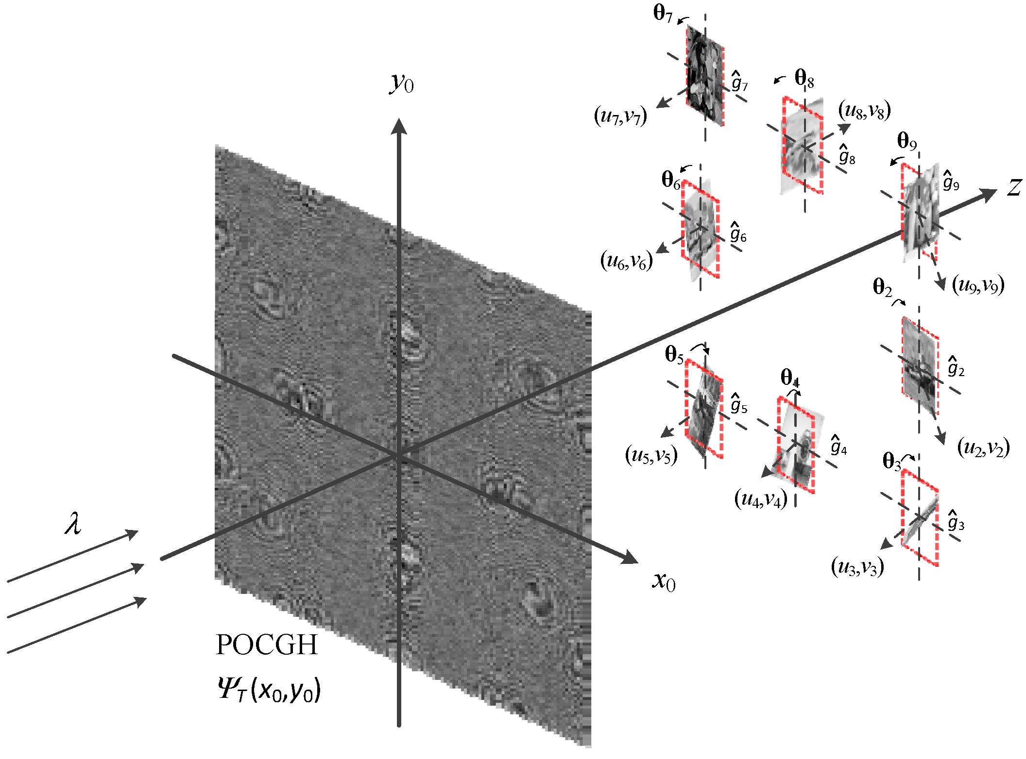
3.1. Angle Multiplexing at the Image Reconstruction Plane

Figure 3 shows the first type of angle manipulation in which the rotation is adapted on only the image reconstruction plane. Here, the rotation angles { ϕ x n ,   ϕ y n } at the POCGH plane are zeros and x 0 = x 0 ,   y 0 = y 0 . To reduce the crosstalk among the reconstructed images, the eight target images are translated to the different locations. A specific target image gn can only be reconstructed at its predefined position, ( u n , v n ) , when the reconstruction plane has the corresponding rotation angle Θ n . Otherwise, no images can be reconstructed, and only the noise-like pattern is shown at the plane. However, the origin of the rotation angle for each image is different. That is, the translated images are based on the reconstruction planes whose origins are different from the original ones found in the optical axis.
Figure 4a,b show the top and lateral views of the reconstruction plane for specific images, respectively. Under this condition, the distance r should be modified according to translation ( u n , v n ) for each target image. Equation (6) shows the determination of new distance r ^ 1 , n for a translated image gn in this optical architecture:
r ^ 1 , n = z 0 +   u n tan θ x + v n tan θ y
From this, and the TFrT formula shown in Equation (5), the light distributions on the rotated plane can be determined:
g ^ n ( x , y ) 1 j λ r ^ 1 , n exp [ j k ( z 0 x sin θ x n y sin θ y ) ] × exp [ j k 2 z 0 ( x 2 cos 2 θ x n + y 2 cos 2 θ y n ) ]     × exp [ j Ψ θ n ( x 0 ,   y 0 ) ] exp [ j k 2 z 0 ( x 0 2 + y 0 2 ) ]     × exp [ j k z 0 ( x x 0 cos θ x n + y y 0 cos θ y n ) ] d x 0 d y 0 ,
where z 0 is the distance between the two origins of the POCGH and reconstruction planes. To reconstruct a specific target image gn at the plane with a rotation angle Θ n , Equation (7) can be expressed in the form shown in Equation (8),
g ^ n ( x , y ) TFrT { exp [ j Ψ θ n ( x 0 ,   y 0 ) ] ; λ ; r ^ 1 , n ; Θ n } | g ^ θ n ( x ,   y ) | exp [ j φ g ^ n ( x ,   y ) ] ,
where Ψ θ n ( x 0 ,   y 0 ) represents the POF retrieved from the MGSA based on the type-1 TFrT shown in Equation (7).
To reduce crosstalk among the reconstructed images, the phase modulation scheme [29] shown in Equation (9) is used, such that each image is translated to different locations centered at the coordinate ( u n , v n ) at the reconstruction plane.
Ψ θ n ( x 0 ,   y 0 ) = Ψ θ n ( x 0 ,   y 0 ) + 2 π ( u n x 0 + v n y 0 ) λ z 0
Thus, Equation (8) can be rewritten as Equation (10):
TFrT { exp [ j Ψ θ n ( x 0 ,   y 0 ) ] ; λ ; r ^ 1 , n ; Θ n } | g ^ θ n ( x     u n ,   y     v n ) | exp [ j φ g ^ n ( x ,   y ) ] .
By summing all the phase-modulated POFs, the final POCGH Ψ T ( x 0 ,   y 0 ) can be obtained:
exp [ j Ψ T ( x 0 ,   y 0 ) ] = n = 1 N exp [ j   Ψ θ n ( x 0 ,   y 0 ) ] .
For demultiplexing, a target image can only be reconstructed at the plane with the corresponding rotation angle. Equation (12) denotes the reconstruction process under a given rotation angle Θ n .
| TFrT { exp [ j Ψ T ( x 0 ,   y 0 ) ] ; λ ; r ^ 1 , n ; Θ n } |       | g ^ θ n ( x     u n ,   y     v n ) exp [ j φ g ^ n ( x u n ,   y v n ) ] + n θ n ( x ,   y ) |         | g ^ θ n ( x u n ,   y v n ) ] + | n θ n ( x ,   y ) | .
Here, a noise term n θ n ( x ,   y ) appears, and the reconstructed image quality can be evaluated by using the correlation coefficient (CC) between the original target and reconstructed images of the same size P by Q. The CC value ρ of two images g and g ^ can be determined by using Equation (13).
ρ = σ g , g ^ σ g σ g ^ = p = 1 P q = 1 Q [ g ( p ,   q ) μ g ] [ g ^ ( p ,   q ) μ g ^ ] p = 1 P q = 1 Q [ g ( p ,   q ) μ g ] 2 p = 1 P q = 1 Q [ g ^ ( p ,   q ) μ g ^ ] 2 ,
where σ g , g ^ denotes the covariance of two images, and σ g and σ g ^ denote the standard deviations of images g and g ^ , respectively.

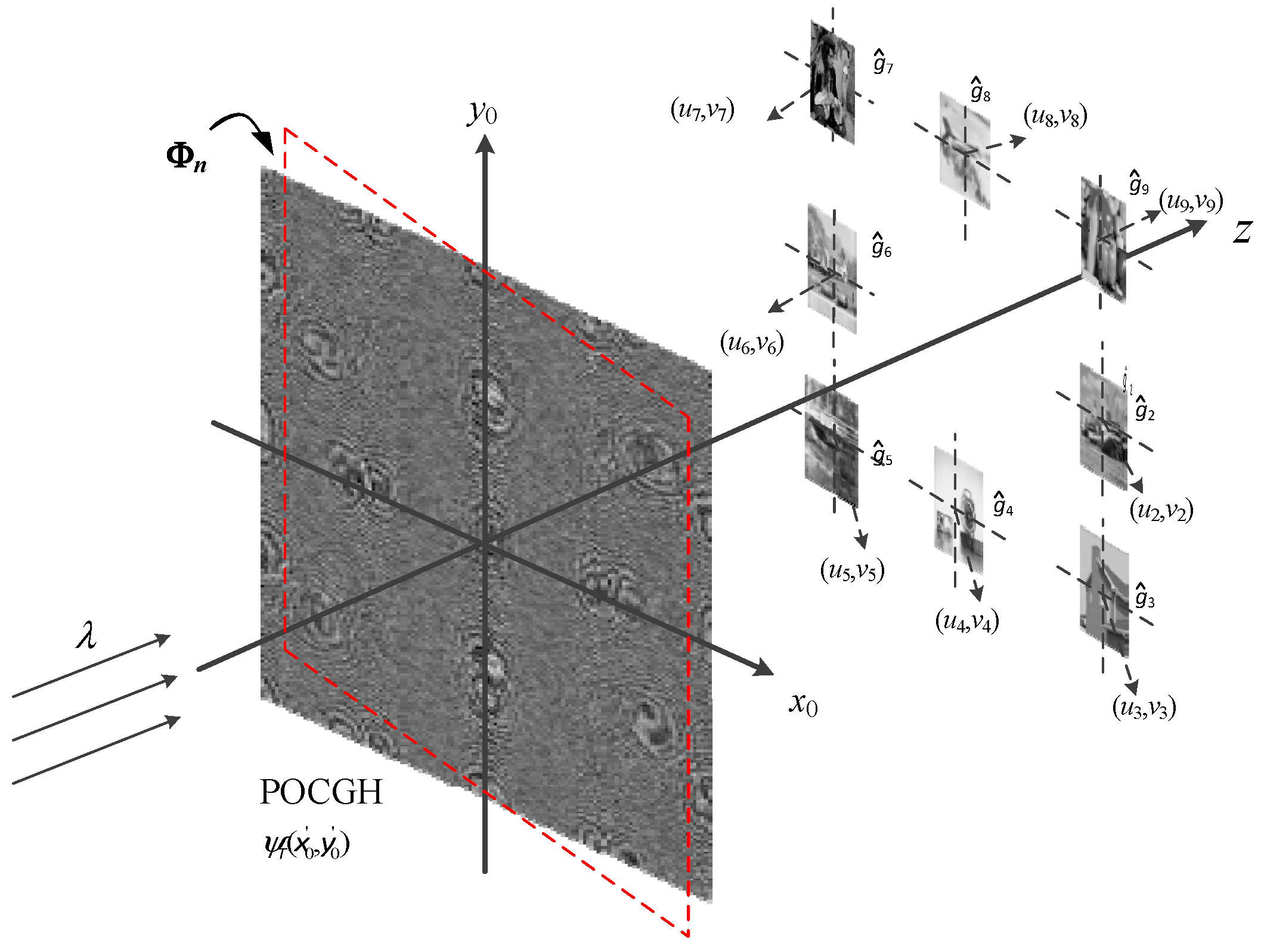
3.2. Angle Multiplexing at the POCGH Plane

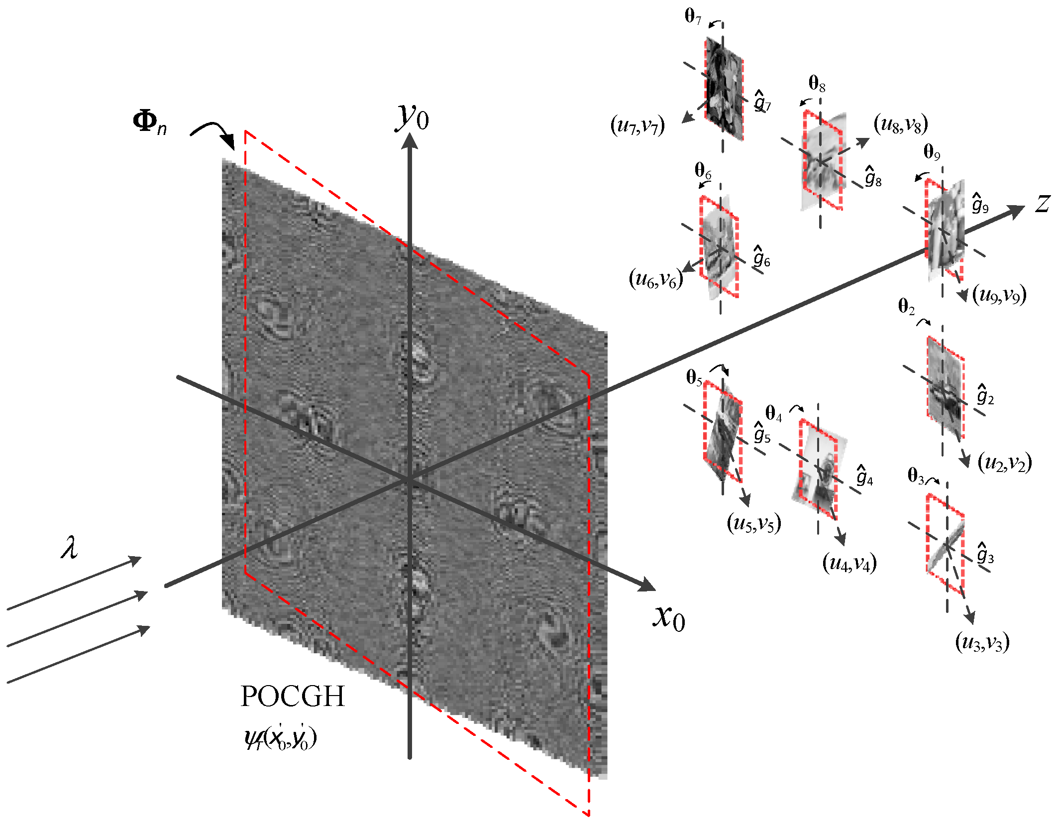
Figure 5 shows the second type of angle manipulation in which the various rotations with respect to the different images are adapted at only the POCGH plane. Here, all the rotation angles { θ x n ,   θ y n } at the reconstruction plane are zero. The eight target images are translated to the different locations. A specific target image gn can only be reconstructed at its predefined position when the POCGH plane corresponds with the rotation angle Φ n . Otherwise, no images can be reconstructed, and only the noise-like pattern results can be detected on the plane. Note that the distance r ^ 2 , n from the rotated POCGH to the reconstruction plane can be determined by using Equation (14) shown below:
r ^ 2 , n = z 0 .
In this case, all the reconstructed images are located at the same plane. Therefore, the spatial translation does not affect the distance r ^ 2 , n to the POCGH plane. Then, the light field distribution on the rotated plane can be determined based on the TFrT formula shown in Equation (15):
g ^ n ( x , y ) 1 j λ r ^ 2 , n exp ( j k z 0 ) exp [ j k 2 z 0 ( x 2     + y 2 ) ] exp [ j Ψ ϕ n ( x 0 ,   y 0 ) ] exp [ j k ( x 0 sin ϕ x n     + y 0 sin ϕ y n ) ] × exp [ j k 2 z 0 ( x 0 2 cos 2 ϕ x n + y 0 2 cos 2 ϕ y n ) ] exp [ j k z 0 ( x x 0 cos ϕ x n     + y y 0 cos ϕ y n ) ] d x 0 d y 0 .
To reconstruct a specific target image gn at the plane with the rotation angle Φ n , Equation (15) can be expressed by the form shown in Equation (16),
g ^ n ( x , y ) TFrT { exp [ j Ψ ϕ n ( x 0 ,   y 0 ) ] ; λ ; r ^ 2 , n ; Φ n } | g ^ ϕ n ( x ,   y ) | exp [ j φ g ^ n ( x ,   y ) ] ,
where Ψ ϕ n ( x 0 ,   y 0 ) represents the POF retrieved from the MGSA based on the type-2 TFrT shown in Equation (15). By applying a similar phase modulation scheme shown in Equation (9), Equation (16) can be rewritten as Equation (17):
TFrT { exp [ j Ψ ϕ n ( x 0 ,   y 0 ) ] ; λ ; r ^ 2 , n ; Φ n } | g ^ ϕ n ( x u n ,   y v n ) | exp [ j φ g ^ n ( x ,   y ) ] .
By summing all the phase-modulated POFs, the final POCGH Ψ T ( x 0 ,   y 0 ) can be obtained:
exp [ j Ψ T ( x 0 ,   y 0 ) ] = n = 1 N exp [ j   Ψ ϕ n ( x 0 , y 0 ) ] .
In demultiplexing, a target image can only be correctly reconstructed when the POCGH has the corresponding rotation angle. Equation (19) denotes the image reconstruction process under a given rotation angle, Φ n .
| TFrT { exp [ j Ψ T ( x 0 ,   y 0 ) ] ; λ ; r ^ 2 , n ; Φ n } | | g ^ ϕ n ( x u n ,   y v n ) | exp [ j φ g ^ n ( x u n ,   y v n ) ] + n ϕ n ( x ,   y ) |      | g ^ ϕ n ( x     u n ,   y     v n ) | + | n ϕ n ( x ,   y ) | .

3.3. Double Angle Multiplexing at the Both Planes

Figure 6 shows the third angle manipulation in which the rotations are adapted at both the POCGH and reconstruction planes. The eight target images are translated to the different locations. A specific target image gn can only be reconstructed at its predefined position when both the POCGH and reconstruction planes have the corresponding rotation angles, Φ n and Θ n , respectively. Otherwise, no images can be reconstructed, and only the noise-like patterns are shown at the plane. The distance r ^ 3 , n between the two rotated planes can be determined by using the same equation as Equation (6). That is, r ^ 3 , n = r ^ 1 , n . The light distribution on the rotated plane can be determined based on the TFrT formula shown in Equation (20):
g ^ n ( x , y ) 1 j λ r ^ 3 , n exp [ j k ( z 0 x sin θ x n y sin θ y n ) ] exp [ j k 2 z 0 ( x 2 cos 2 θ x n + y 2 cos 2 θ y n ) ]    × exp [ j Ψ ϕ n , θ n ( x 0 ,   y 0 ) ] exp [ j k ( ( x 0 sin ϕ x n + y 0 sin ϕ y n ) ] exp [ j k 2 z 0 ( x 0 2 cos 2 ϕ x n        + y 0 2 cos 2 ϕ y n ) ]         × exp [ j k z 0 ( x x 0 cos θ x n cos ϕ x n + y y 0 cos θ y n cos ϕ y n ) ] d x 0 d y 0 .
To reconstruct a specific target image gn at the plane with the rotation angle Φ n , the rotation angle Θ n at the POCGH plane is also required. Equation (20) can be expressed in the form shown in Equation (21),
g ^ n ( x , y ) TFrT { exp [ j Ψ ϕ n , θ n ( x 0 ,   y 0 ) ] ; λ ; r ^ 3 , n ; Φ n ; Θ n } | g ^ ϕ n , θ n ( x ,   y ) | exp [ j φ g ^ n ( x ,   y ) ] ,
where Ψ ϕ n , θ n ( x 0 ,   y 0 ) represents the POF retrieved from the MGSA based on the type-3 TFrT shown in Equation (20). By applying similar phase modulation schemes to those already shown in Equation (9), Equation (21) can be rewritten as Equation (22):
TFrT { exp [ j Ψ ϕ n , θ n ( x 0 ,   y 0 ) ] ; λ ; r ^ 3 , n ; Φ n ; Θ n } | g ^ ϕ n , θ n ( x     u n ,   y     v n ) | exp [ j φ g ^ n ( x ,   y ) ] .
By summing all the phase-modulated POFs, the final POCGH Ψ T ( x 0 ,   y 0 ) can be obtained:
exp [ j   Ψ T ( x 0 ,   y 0 ) ] = n = 1 N exp [ j   Ψ ϕ n , θ n ( x 0 ,   y 0 ) ] .
In demultiplexing, a target image can only be successfully reconstructed when both the POCGH and reconstruction planes have the correct rotation angles Φ n and Θ n . Equation (24) denotes the image reconstruction process under the given rotation angles Φ n and Θ n .
| TFrT { exp [ j Ψ T ( x 0 ,   y 0 ) ] ; λ ; r ^ 3 , n ; Φ n ; Θ n } | | g ^ ϕ n , θ n ( x     u n ,   y     v n ) exp [ j φ g ^ n ( x u n , y v n ) + n ϕ n , θ n ( x ,   y ) |      | g ^ ϕ n , θ n ( x     u n ,   y     v n ) | + | n ϕ n , θ n ( x ,   y ) ] .

4. Results and Discussion

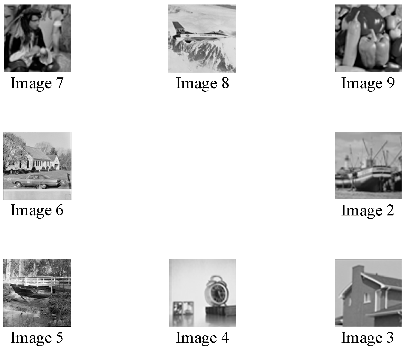
To verify the proposed method, eight grayscale images of size 128 by 128 are used as the target images and their number and relative position is shown in Figure 7. We do not allocate a target image at the center of reconstruction plane because of the zero-order light issue in the optical implementation. Let the POCGH be of size 1920 by 1080 with a 6.8 μm pitch, the wavelength of the incident light be 632 nm, and the distance z0 be 1.3 m, so that the approximations used in deriving the TFrT equations can be satisfied. All three optical architectures shown in Figure 3, Figure 5 and Figure 6 follow identical parameters. To limit the scaling effects caused by the rotation, we select all the rotation angles that are smaller than 15°. Table 1 shows the rotation angles of the POCGHs and reconstruction planes for the eight target images in the three optical architectures. Note that only the rotation angles Θ n and Φ n are used in the first and second architectures, respectively, while the both angles are required for the functioning of the third architecture.
In Figure 2, the POF of each target image is retrieved by using the MGSA based on the TFrT. For multiplexing, as seen in Figure 3, Figure 5 and Figure 6, the POF size is the same as the POCGH, and thus, each image must be placed into the center of an extended image plane of the same size. The remaining part of the plane is then filled using a zero padding scheme. Then, using the phase modulation and summation processes for the POFs of eight target images, we finally obtain the POCGHs for the three types of angle manipulation. A specific image at the corresponding location can be reconstructed only when the correct parameters in the TFrT are used. For example, 
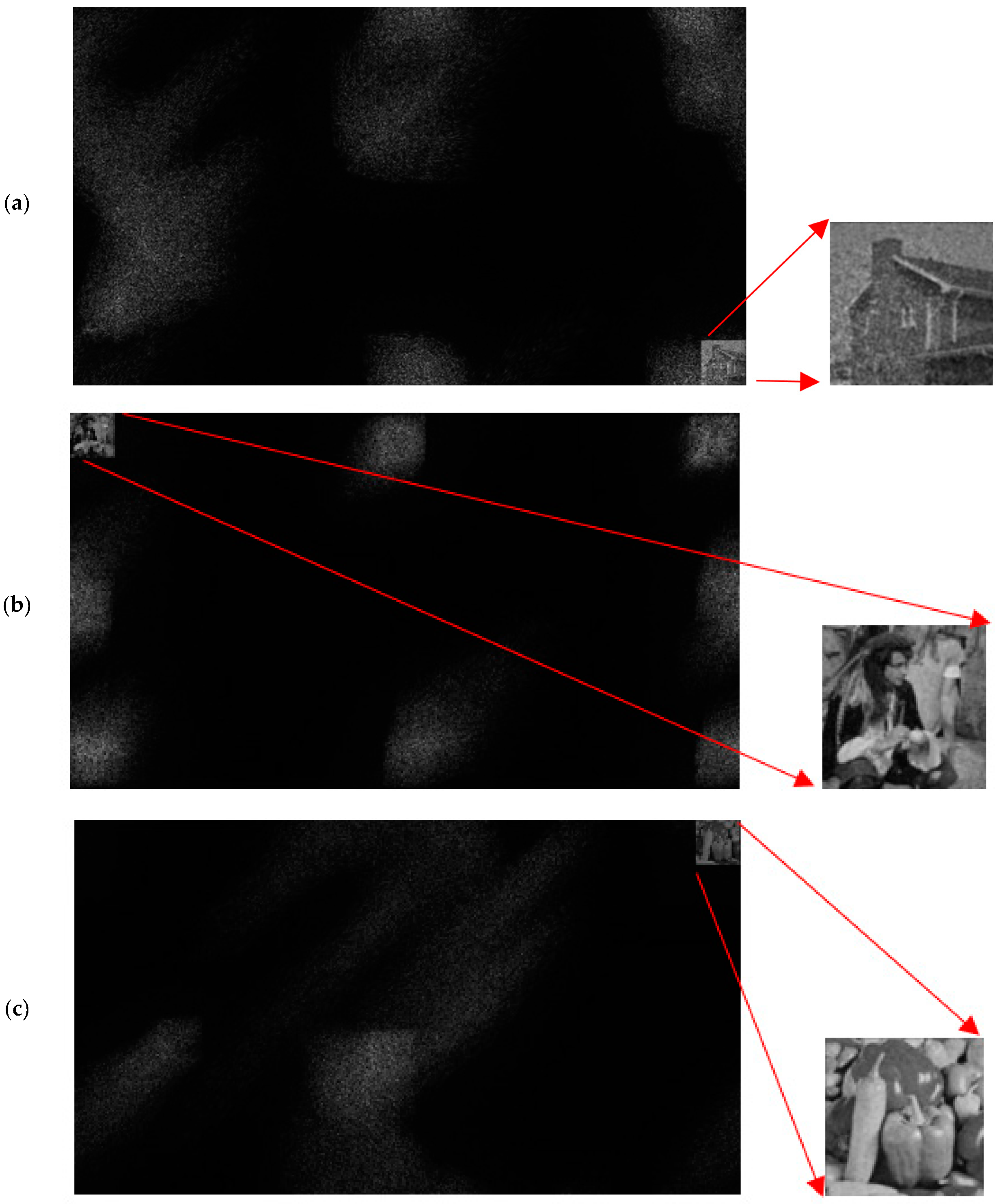
Figure 8a–c shows that we have successfully reconstructed the “House,” “Indian,” and “Peppers” images at the corresponding locations at the reconstruction planes with the correct rotation angles Θ 3 , Φ 7 , and ( Φ 9 , Θ 9 ) in their corresponding optical architectures, respectively. Only one image result is shown, as the others can be also reconstructed in all three optical architectures with their corresponding angles. Note that we applied Gaussian filtering to each reconstructed image to improve the quality.
Table 2, Table 3 and Table 4 show the CC values of the eight reconstructed images of the three optical architectures under the selected rotation angles Θ n and Φ n for the different target images shown in Table 1. As shown in these three tables, the highest CC values (shown in bold faces) appear at the diagonals, while other values are all close to zero. That is, the eight target images can only be reconstructed when applying the correct rotation angles on the POCGH and/or reconstruction planes. Most of the CC values of all the images reconstructed with the three types of angle manipulation are greater than 0.9, and the others are all greater than 0.8, depending on the several factors: First, the complexity of the image content. Second, the crosstalk caused from the multiplexing effects, as we can see the noise terms in Equations (12), (19), and (24). The noise magnitude increases as the number of multiplexed images increases. In addition, the approximations used in deriving the TFrT formula also affect the image quality. Figure 8a–c show that the other images are all noise-like and unrecognizable, as a particular set of rotation angles is only effective for one image.
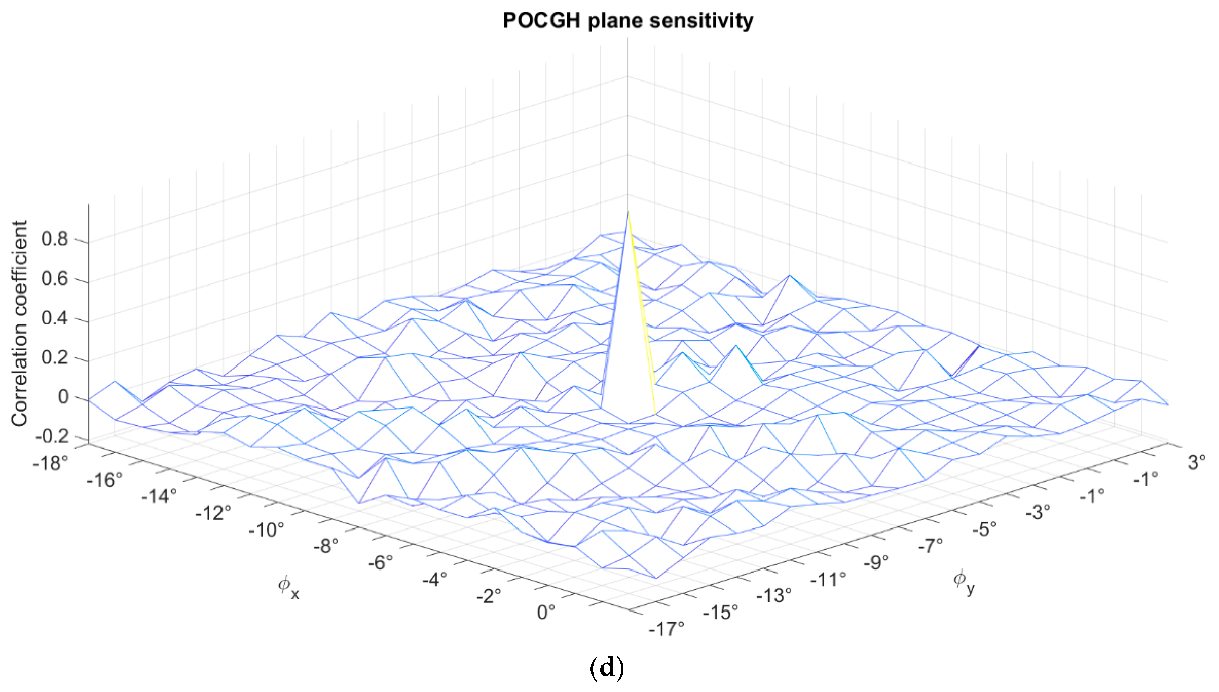
Next, we undertake an investigation into the angle sensitivity in the computer simulations. Figure 9a–d show the CC values of the reconstructed “Peppers” image when the rotation angles are maximally shifting ± 10° (with a step size 1°) from their correct values. Consider the first optical architecture shown in Figure 3. Figure 9a shows the CC values decrease very quickly, which represents a high sensitivity in this type of angle manipulation. Figure 9b shows the CC values when considering the same angle shifting at the POCGH plane in the second architecture. The CC value decreases more slowly than in Figure 9a. That is, the sensitivity is lower in this type of angle manipulation. Figure 9c,d show the CC values when the angle shift only occurs at the POCGH and image reconstruction planes, respectively, in the third optical architecture shown in Figure 6. Except for the center peak CC values, the other CC values are all lower than 0.2 in Figure 9c,d. Therefore, the angle sensitivity in these two planes is high enough in the third type of angle manipulation.
As an image encryption system, the key space of the proposed method is investigated. Let the POCGH be of size M by N pixels and of resolution L bits to represent the phase information in each pixel. The rotation angles for both the POCGH and image reconstruction planes are within the same range [− ω , + ω ], 15 o ω 15 o . Consider the brute force attack for revealing a specific target image. The key spaces are M × N × L × 30 for the first and second types (single-plane rotation) and M × N × L × 30 2 for the third type (double-plane rotation) of angle manipulation under a fixed distance z0 and a given wavelength λ. For the POCGH with the size of 1920 by 1080 and 8 bits resolution, the key spaces for the brute force attack are 497,664,000 and 14,929,920,000 for the single- and double-plane rotation, respectively.
The image decryption part of the proposed method can be implemented by using both the optical and digital ways. The computer simulation verified the correctness of the proposed method when used in a digital system. The runtime analysis is based on the PC with the specifications as follows: CPU: Intel(R) Core(TM) [email protected], RAM: DDR3 1600MHz 8G. The programming was implemented using MATLAB R2019b in Windows 10 operation system. Let the iteration number in the MGSA for retrieving the POF for each target image be 100. Table 5 shows the computation time (in seconds) for the three different types of angle manipulation in the computer simulation. The required computation time in the first and second types is similar, because both types employ only single-plane rotation, while the third-type takes longer, because it employs double-plane rotation.
Experiment validation is useful for improving the significance of the proposed method. However, we do not have experimental implementation in the current stage. The contributions of optical experiments on image multiplexing based on various manipulation schemes have been widely proposed since last decade [36,37,38,39,40,41]. For example, the multiplexing methods for images and movies can be based on aperture-modulated optical systems [36], joint transform correlator architectures [37,38], using the CGH and maximum length cellular automata [39], the DRPE and orthogonal phase encoding [40], and the multiplexed view-coded orbital angular momentum beam [41]. The practical issues associated with the optical experiments of the proposed method can be explored in these studies.

5. Conclusions

This paper proposed a new angle multiplexing method, implemented by three different types of angle manipulation on the POCGH and/or image reconstruction planes. Compared to previous wavelength and position multiplexing techniques [21], the proposed angle multiplexing method can provide greater flexibility, because the selection of rotation angles and the various types of angle manipulation contain greater variety. Scaling effects due to the rotation of the POCGH or reconstruction planes have not been considered yet; however, it is expected that this will be included in future optical experiments. Furthermore, the pixilation and scaling effects due to the rotation of the POCGH or reconstruction planes and the pixel response of the device on which the POCGH is displayed have not been considered yet; it is expected that these will also be included in future optical experiments.
The proposed method can be combined with other multiplexing techniques such as wavelength based and positional ones [22,23,24]. Therefore, a much higher system security level can be achieved, considering that multiplexed images are encrypted by default and can only be correctly decrypted when all required parameters in the TFrT are available. Additionally, the methods proposed here show great potential for 3-D image projection, as the rotated images are no longer within the same two-dimensional plane.

Author Contributions

H.T.C. and C.-Y.C. developed the theoretical formalism and performed the analytic calculations. Y.-T.W. performed the numerical simulations. H.T.C. contributed to the writing, review, and editing of the manuscript. All authors have read and agreed to the published version of the manuscript.

Funding

This research and the APC were funded by Ministry of Science and Technology (MOST) in Taiwan, grant number MOST 108-2221-E-224-039.

Conflicts of Interest

The authors declare no conflict of interest.

References

  1. Javidi, B.; Carnicer, A.; Yamaguchi, M.; Nomura, T.; Pérez-Cabré, E.; Millan, M.S.; Nishchal, N.K.; Torroba, R.; Barrera, J.F.; He, W.; et al. Roadmap on optical security. J. Opt. 2016, 18, 083001. [Google Scholar] [CrossRef]
  2. Refregier, P.; Javidi, B. Optical image encryption based on input plane and Fourier plane random encoding. Opt. Lett. 1995, 20, 767–769. [Google Scholar] [CrossRef] [PubMed]
  3. Chang, H.T.; Lu, W.C.; Kuo, C.J. Multiple-phase retrieval for optical security systems using random phase encoding. Appl. Opt. 2002, 41, 4825–4834. [Google Scholar] [CrossRef] [PubMed]
  4. Chang, H.T. Optical image encryption using separate amplitude-based virtual image and iteratively-retrieved phase information. Opt. Eng. 2001, 40, 2165–2171. [Google Scholar] [CrossRef] [Green Version]
  5. Yeh, C.H.; Chang, H.T.; Chien, H.C.; Kuo, C.J. Design of cascaded phase keys for hierarchical security system. Appl. Opt. 2002, 41, 6128–6134. [Google Scholar] [CrossRef]
  6. Chang, Y.C.; Chang, H.T.; Kuo, C.J. Hybrid image cryptosystem based on dyadic phase displacement in the Fourier domain. Opt. Commun. 2004, 236, 245–257. [Google Scholar] [CrossRef]
  7. Chang, H.T.; Chen, C.T. Enhanced optical image verification based on joint transform correlator adopting Fourier hologram. Opt. Rev. 2004, 11, 165–169. [Google Scholar] [CrossRef]
  8. Chang, H.T.; Chen, C.T. Asymmetric-image verification for security optical system based on joint transform correlator. Opt. Commun. 2004, 239, 43–54. [Google Scholar] [CrossRef]
  9. Nishchal, N.K.; Joseph, J.; Singh, K. Securing information using fractional Fourier transform in digital holography. Opt. Commun. 2004, 235, 253–259. [Google Scholar] [CrossRef]
  10. Chang, H.T.; Chen, C.C. Fully phase asymmetric image verification system based on joint transform correlator. Opt. Express 2006, 14, 1458–1467. [Google Scholar] [CrossRef]
  11. Situ, G.; Zhang, J. Double random-phase encoding in the Fresnel domain. Opt. Lett. 2004, 29, 1584–1586. [Google Scholar] [CrossRef] [PubMed]
  12. Gerchberg, R.W.; Saxton, W.O. A practical algorithm for the determination of phase from image and diffraction plane pictures. Optik 1972, 35, 237–246. [Google Scholar]
  13. Goodman, J. Introduction to Fourier Optics, 3rd ed.; Chap. 4; Roberts and Company Publishers: Englewood, CO, USA, 2005. [Google Scholar]
  14. Leseberg, D.; Frère, C. Computer-generated holograms of 3-D objects composed of tilted planar segments. Appl. Opt. 1988, 27, 3020–3024. [Google Scholar] [CrossRef] [PubMed]
  15. Tommasi, T.; Bianco, B. Frequency analysis of light diffraction between rotated planes. Opt. Lett. 1992, 17, 556–558. [Google Scholar] [CrossRef] [PubMed]
  16. Tommasi, T.; Bianco, B. Computer-generated holograms of tilted planes by a spatial frequency approach. J. Opt. Soc. Am. A 1993, 10, 299–305. [Google Scholar] [CrossRef]
  17. Matsushima, K.; Schimmel, H.; Wyrowski, F. Fast calculation method for optical diffraction on tilted planes by use of the angular spectrum of plane waves. J. Opt. Soc. Am. A 2003, 20, 1755–1762. [Google Scholar] [CrossRef]
  18. De Nicola, S.; Finizio, A.; Pierattini, G.; Ferraro, P.; Alfieri, D. Angular spectrum method with correction of anamorphism for numerical reconstruction of digital holograms on tilted planes. Opt. Express 2005, 13, 9935–9940. [Google Scholar] [CrossRef]
  19. Jeong, S.J.; Hong, C.K. Pixel-size-maintained image reconstruction of digital holograms on arbitrarily tilted planes by the angular spectrum method. Appl. Opt. 2008, 47, 3064–3071. [Google Scholar] [CrossRef]
  20. Yamamoto, K.; Ichihashi, Y.; Senoh, T.; Oi, R.; Kurita, T. Calculating the Fresnel diffraction of light from a shifted and tilted plane. Opt. Express 2012, 20, 12949–12958. [Google Scholar] [CrossRef]
  21. Chang, C.; Xia, J.; Jiang, Y. Holographic image projection on tilted planes by phase-only computer generated hologram using fractional Fourier transformation. J. Disp. Technol. 2014, 10, 107–113. [Google Scholar] [CrossRef]
  22. Chang, C.; Xia, J.; Wu, J.; Lei, W.; Xie, Y.; Kang, M.; Zhang, Q. Scaled diffraction calculation between tilted planes using nonuniform fast Fourier transform. Opt. Express 2014, 22, 17331–17340. [Google Scholar] [CrossRef] [PubMed]
  23. Arai, D.; Shimobaba, T.; Murano, K.; Endo, Y.; Hirayama, R.; Hiyama, D.; Kakue, T.; Ito, T. Acceleration of computer-generated holograms using tilted wavefront recording plane method. Opt. Express 2015, 23, 1740–1747. [Google Scholar] [CrossRef] [PubMed]
  24. Xiao, Y.; Tang, X.; Qin, Y.; Peng, H.; Wang, W.; Zhong, L. Nonuniform fast Fourier transform method for numerical diffraction simulation on tilted planes. J. Opt. Soc. Am. A 2016, 33, 2027–2033. [Google Scholar]
  25. Stock, J.; Worku, N.G.; Gross, H. Coherent field propagation between tilted planes. J. Opt. Soc. Am. A 2017, 34, 1849–1855. [Google Scholar] [CrossRef] [PubMed]
  26. Vilardy, O.; Juan, M.; Jimenez, C.J.; Torres, M.; Cesar, O. Optical image encryption system using several tilted planes. Photonics 2019, 6, 116. [Google Scholar] [CrossRef] [Green Version]
  27. Situ, G.; Zhang, J. Multiple-image encryption by wavelength multiplexing. Opt. Lett. 2005, 30, 1306–1308. [Google Scholar] [CrossRef]
  28. Situ, G.; Zhang, J. Position multiplexing for multiple-image encryption. J. Opt. A 2006, 8, 391–397. [Google Scholar] [CrossRef]
  29. Hwang, H.-E.; Chang, H.T.; Lai, W.-N. Multiple-image encryption and multiplexing using modified Gerchberg-Saxton algorithm and phase modulation in Fresnel transform domain. Opt. Lett. 2009, 34, 3917–3919. [Google Scholar] [CrossRef]
  30. Chang, H.T.; Hwang, H.-E.; Lee, C.L.; Lee, M.-T. Wavelength multiplexing multiple-image encryption using cascaded phase-only masks in Fresnel transform domain. Appl. Opt. 2011, 50, 710–716. [Google Scholar] [CrossRef]
  31. Chang, H.T.; Hwang, H.-E.; Lee, C.L. Position multiplexing multiple-image encryption using cascaded phase-only masks in Fresnel transform domain. Opt. Commun. 2011, 284, 4146–4151. [Google Scholar] [CrossRef]
  32. Hwang, H.-E.; Chang, H.T.; Lai, W.-N. Fast double-phase retrieval in Fresnel domain using modified Gerchberg-Saxton algorithm for lensless optical security systems. Opt. Express 2009, 17, 13700–13710. [Google Scholar] [CrossRef] [PubMed]
  33. Chang, H.T.; Lin, C.-H.; Chen, C.-Y. Image multiplexing and authentication based on double phase retrieval in Fresnel transform domain. Opt. Commun. 2017, 389, 150–158. [Google Scholar] [CrossRef]
  34. Chang, H.T.; Wang, Y.; Chen, C.Y. Optical image encryption using angle multiplexing in the Fresnel transform domain. In Proceedings of the 24th Congress of the International Commission for Optics (ICO-24), Tokyo, Japan, 21–25 August 2017; pp. 4–17. [Google Scholar]
  35. Chang, H.T.; Wang, Y.-T.; Chou, Y.-H. On the rotation angle of reconstruction plane in optical phase-only image encryption and multiplexing. In Imaging and Applied Optics 2018 (3D, AO, AIO, COSI, DH, IS, LACSEA, LS&C, MATH, pcAOP), Proceedings of the Adaptive Optics: Analysis, Methods & Systems, Orlando, FL, USA, 24–28 June 2018; OSA Technical Digest; Paper JM4A.20; Optical Society of America: Washington, DC, USA, 2018. [Google Scholar]
  36. Barrera, J.F.; Henao, R.; Tebaldi, M.; Torroba, R.; Bolognini, N. Multiple image encryption using an aperture-modulated optical system. Opt. Commun. 2006, 261, 29–33. [Google Scholar] [CrossRef]
  37. Rueda, E.; Barrera, J.F.; Henao, R.; Torroba, R. Optical image multiplexing encryption using digital holography in a JTC architecture. In Advances in Imaging, Proceedings of the Digital Holography and Three-Dimensional Imaging 2009, Vancouver, BC, Canada, 26–30 April 2009; OSA Technical Digest (CD); Paper JTuB3; Optical Society of America: Washington, DC, USA, 2009. [Google Scholar]
  38. Barrera, J.F.; Tebaldi, M.; Ríos, C.; Rueda, E.; Bolognini, N.; Torroba, R. Experimental multiplexing of encrypted movies using a JTC architecture. Opt. Express 2012, 20, 3388–3393. [Google Scholar] [CrossRef] [PubMed]
  39. Xiao, D.; Li, X.; Liu, S.-J.; Wang, Q.-H. Encryption and display of multiple-image information using computer-generated holography with modified GS iterative algorithm. Opt. Commun. 2018, 410, 488–495. [Google Scholar] [CrossRef]
  40. Kim, Y.; Sim, M.; Moon, I. Secure storage and retrieval schemes for multiple encrypted digital holograms with orthogonal phase encoding multiplexing. Opt. Express 2019, 27, 22147–22160. [Google Scholar] [CrossRef]
  41. Chu, J.; Chu, D.; Smithwick, Q. Encoding and multiplexing of 2D images with orbital angular momentum beams and the use for multiview color displays. Research 2019, 2019, 9564593. [Google Scholar] [CrossRef] [Green Version]
Figure 1. Generalized optical diffraction architecture for a single image reconstruction using rotation manipulation on the POF and reconstruction planes.
Photonics 07 00001 g001
Figure 2. Block diagram of the general optical image-multiplexing method.
Photonics 07 00001 g002
Figure 3. The first type of angle manipulation for the proposed method, in which only the reconstruction planes are rotated with an angle Θ n .
Photonics 07 00001 g003
Figure 4. (a) Top view and (b) lateral view of the translated images in the reconstruction plane whose origin is different from the original one.
Photonics 07 00001 g004
Figure 5. The second type of angle manipulation for the proposed method, in which only the POCGH are rotated with angle Φ n .
Photonics 07 00001 g005
Figure 6. The third type of angle manipulation for the proposed method, in which the POCGH and reconstruction planes are rotated with the angles Φ n and Θ n , respectively.
Photonics 07 00001 g006
Figure 7. The eight target images used in the computer simulation and their relative locations at the reconstruction plane.
Photonics 07 00001 g007
Figure 8. The three reconstructed images (and their magnified and filtered versions) (a) “House,” (b) “Indian,” and (c) “Peppers” at the output planes in the first, second, and third types of angle manipulation, respectively.
Photonics 07 00001 g008
Figure 9. Angle sensitivities represented by CC values of the reconstructed “Peppers” image under the three different architectures: (a) angle shifting at the reconstruction plane when both the POCGH and reconstruction planes are perpendicular to the optical axis; (b) angle shifting at the rotated POCGH plane when the reconstruction plane is fixed; (c) angle shifting at the reconstruction plane when the rotated POCGH is fixed; (d) angle shifting at the POCGH plane when the rotated reconstruction plane is fixed.
Photonics 07 00001 g009aPhotonics 07 00001 g009b
Table 1. Rotation angles used in the simulations of the three types of angle manipulation.
Φ n Θ n
Image # ϕ x n ϕ y n θ x n θ y n
210°12°13°15°
310°12°
413°15°
5
6−15°−13°−5°−1°
7−5°−3°−12°−10°
8−12°−10°−8°−7°
9−8°−7°−15°−13°
Table 2. CC values of all the reconstructed images for the first type of angle manipulation (rotation on the reconstruction plane).
ANGLEIMAGE #
23456789
Θ 2 0.920.430.000.28−0.07−0.07−0.030.06
Θ 3 0.070.88−0.250.010.10−0.120.07−0.08
Θ 4 0.06−0.220.87−0.030.13−0.030.02−0.03
Θ 5 0.18−0.300.210.91−0.02−0.17−0.07−0.02
Θ 6 −0.140.00−0.150.040.92−0.130.100.00
Θ 7 0.160.23−0.03−0.210.090.93−0.120.04
Θ 8 0.10−0.400.360.040.22−0.070.950.00
Θ 9 −0.130.230.070.390.07−0.160.040.96
The bold face represents a vector.
Table 3. CC values of all the reconstructed images for the second type of angle manipulation (rotation on the POCGH plane).
ANGLEIMAGE #
23456789
Φ 2 0.86−0.160.370.30−0.09−0.12−0.160.12
Φ 3 0.070.810.330.40−0.12−0.07−0.170.01
Φ 4 0.14−0.280.960.28−0.05−0.12−0.120.08
Φ 5 −0.030.280.280.90−0.110.02−0.170.00
Φ 6 0.04−0.19−0.010.030.850.220.160.21
Φ 7 −0.120.230.240.25−0.110.94−0.160.16
Φ 8 −0.07−0.060.230.050.030.280.950.21
Φ 9 −0.140.260.240.12−0.050.35−0.080.96
The bold face represents a vector.
Table 4. CC values of the reconstructed images for the third type of angle manipulation (rotations on both the POCGH and reconstruction planes).
ANGLEIMAGE #
23456789
Φ 2 , Θ 2 0.920.19−0.340.20−0.02−0.160.040.01
Φ 3 , Θ 3 −0.200.960.09−0.09−0.030.030.010.14
Φ 4 , Θ 4 0.000.050.86−0.01−0.07−0.080.020.13
Φ 5 , Θ 5 0.23−0.090.110.91−0.030.010.02−0.01
Φ 6 , Θ 6 −0.20−0.260.21−0.310.850.18−0.04−0.02
Φ 7 , Θ 7 −0.25−0.140.200.100.030.920.020.09
Φ 8 , Θ 8 −0.260.22−0.220.21−0.090.190.950.09
Φ 9 , Θ 9 −0.270.24−0.130.230.09−0.140.040.91
The bold face represents a vector.
Table 5. Computation time (in seconds) for determining the eight POFs, POCGHs, and image decryption in the three different types of angle manipulation in the proposed method.
8 POFsPOCGHTotal/Average Image Decryption
Type-1656.383.862.38/0.3
Type-2614.343.792.40/0.3
Type-3768.914.393.22/0.4

