2. Optical Diffraction on Tilted Planes
We use the technique based on the angular spectrum of plane waves and coordinate rotation in the Fourier domain described in reference [
10] in order to compute the optical diffraction on tilted planes. Let
and
be a source field and its spectrum, in the source plane; the coordinates of the source plane are denoted by
x and
y. The distance between the source plane and the reference plane is
and the optical propagation of the source field is along the
z axis. Let
be the source spectrum in an intermediate plane or reference plane, which is parallel to the source plane, and that its coordinates share the origin with the reference coordinates; the coordinates of the reference plane are represented by
and
.
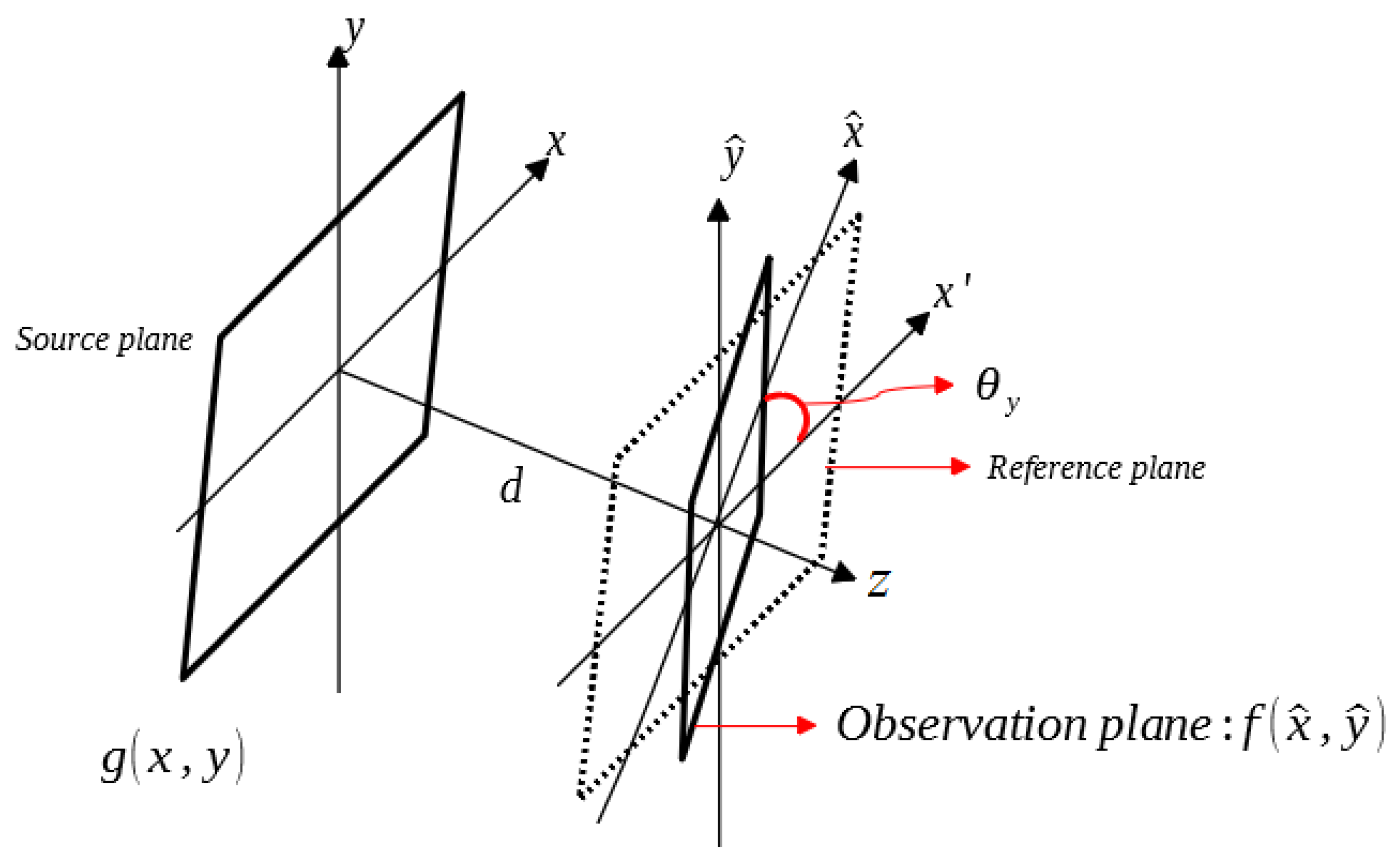
Figure 1 shows the optical scheme for the diffraction on a tilted plane where the coordinates of the observation plane are denoted by
and
. Using the standard formula of the angular spectrum of plane waves [
6], we can obtain
where
u and
v are the spatial frequency coordinates and
is the wavelength. The rotation matrix
can be used to transform the reference coordinates into the observation coordinates. Therefore, the wave vectors of these coordinates can also be transformed into each other by
with
where
represents the component in
z direction of the wave vector. The spatial frequency coordinates
and
are related to the source spectrum in the reference (without tilt) and observation (with tilt) planes, respectively. The rotation matrices
that produce a tilted plane for
Figure 1 are
where the rotation matrix
is a rotation around the
x axis, which produces a tilted plane with respect to the
y axis and the rotation matrix
is a rotation around the
y axis and this produces a tilted plane with respect to the
x axis. The tilted plane of
Figure 1 is described by the rotation matrix
.
The Fourier frequencies in the reference coordinates are related to those in the observation coordinates in the following form
The spectrum in the observation coordinate is given by the spectrum in the reference coordinate according to
The complex amplitudes of the field in the observation coordinates with the same energy as the complex amplitudes of the field in the reference coordinates are given by
where the Jacobian is
3. DRPE Using Tilted Plane: Optical Image Encryption and Decryption Systems
The DRPE technique uses two RPMs in order to encrypt the information of the original image
; the values of
are in the interval of [0, 1]. The two RPMs are represented by
where
,
,
and
are spatial coordinates,
and
are normalized positive function generated randomly, independent statistically and their values are uniformly distributed in the interval of [0, 1] [
1].
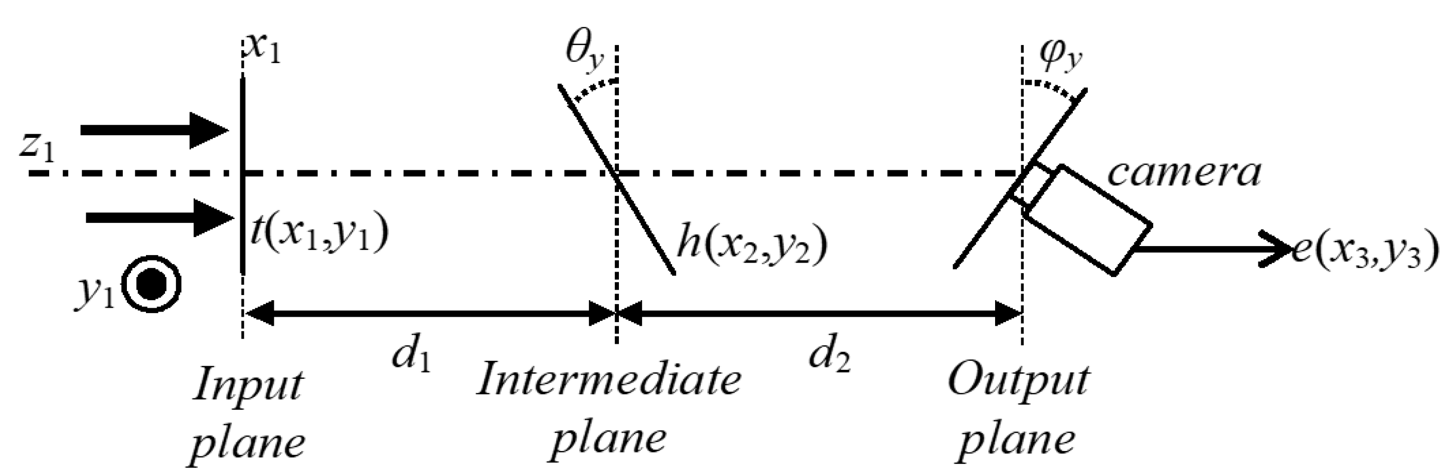
Figure 2 depicts the optical scheme based on the DRPE technique and the optical diffraction on two tilted planes.
The distribution
of the input plane of the encryption system of
Figure 2 is composed by the original image
to encrypt placed against the RPM
The optical diffraction of the distribution
on the tilted plane placed at the distance
with respect to the input plane of the encryption system is given by the distribution
and it is computed using the procedure described in
Section 2. We use the following parameters and functions to compute
The RPM
is multiplied by the image
with the purpose of obtaining the intermediate distribution
. The image
is optically tilted to the intermediate plane of the encryption system and the resulting image is the input for the second optical diffraction on the tilted plane placed at the distance
with respect to the intermediate plane, which corresponds to the output plane of the encryption system. We apply again the approach described in
Section 2 using the optically tilted distribution obtained from
, the propagation distance
and the rotation matrix
, in order to compute the encrypted image
.
The RPM
, the propagation distances
and
, and the angles of the tilted planes
and
, are the security keys of the encryption system and the RPM
is used to spread the information content of the original image
onto the encrypted image
[
1]. When the angles of the tilted planes are equal to
and
, the proposed encryption system in this work is reduced to the DRPE encryption system in the Fresnel domain [
8].
The decryption system is performed by digital computations and it is computed in the reverse order of the encryption system using the encrypted image
and the method presented in
Section 2 along with the following five security keys: the complex conjugated of the RPM
, the propagation distances
and
, and the two angles
and
. For the decryption system, the input and intermediate planes are tilted at an angle of
and
, respectively. The output plane of the decryption system is not tilted.
A second rotation around the
x axis (
or
for the intermediate and output planes of the encryption system, respectively) produces a tilted plane with respect to the
y axis and the method of
Section 2 can be used in order to obtain the optical diffraction over the final tilted plane. The two new tilt angles
and
can be considered to be new security keys of the proposed encryption and decryption systems.
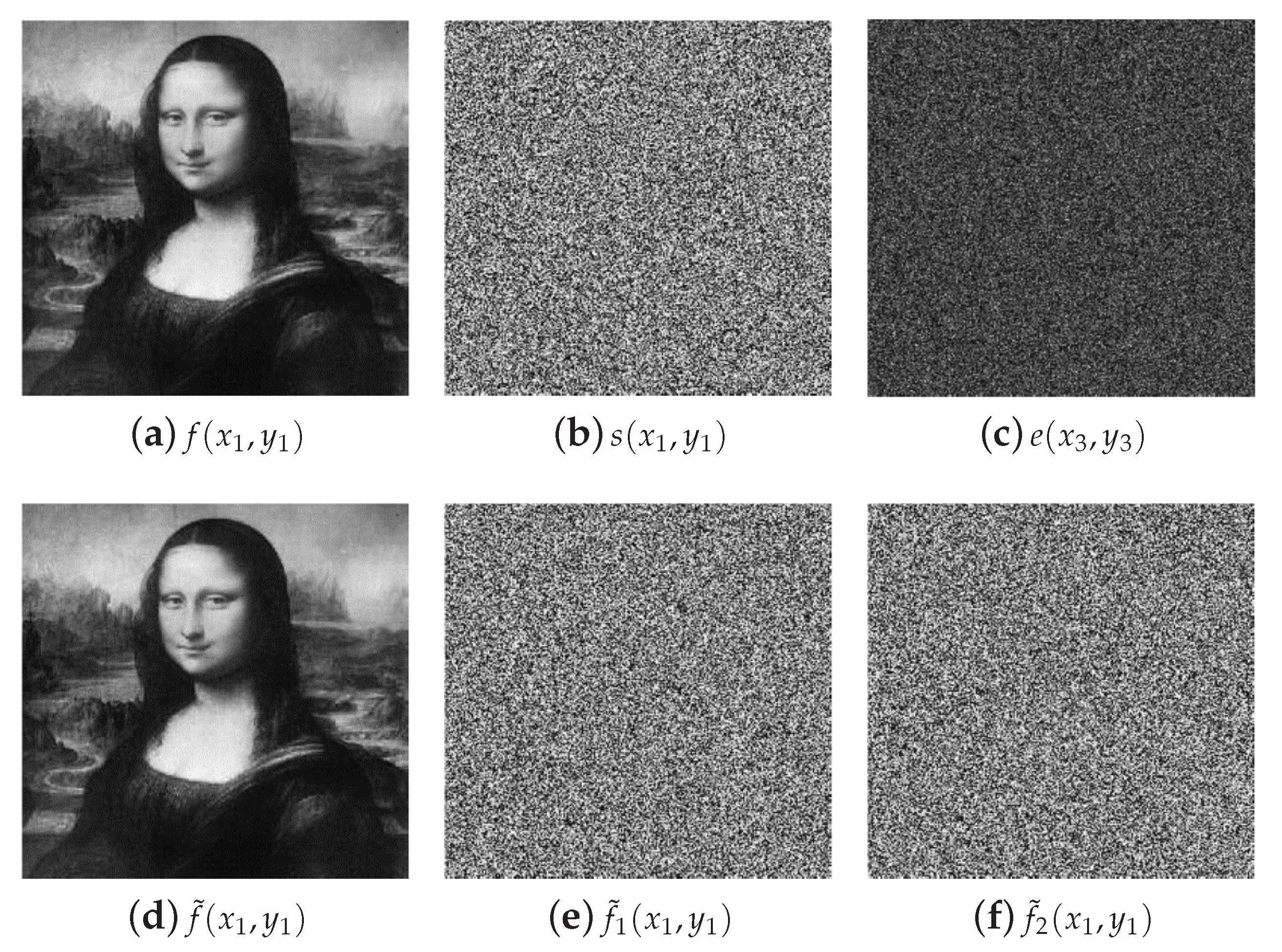
The results of the numerical simulations for the security system proposed in this section are shown in
Figure 3. The original image
to encrypt and the random code image
of the RPM
are depicted in
Figure 3a,b, respectively. The random code image
of the RPM
has different values but the same appearance of the image shown in
Figure 3b. The encrypted image
is presented in
Figure 3c for the security keys:
mm,
mm,
,
and the RPM
. This encrypted image is a noisy pattern that does not reveal any information of the original image
. When the decryption system is performed using the encrypted image
and the five correct security keys (
,
,
,
and
), the original image
is retrieved at the output plane of the decryption system. The decrypted image
is depicted in
Figure 3d. We use the metric of the root mean square error (RMSE) between the decrypted images
and the original image
with the purpose of evaluating the image quality of the decrypted images. The values of the RMSE metric to evaluate the image quality are values between 0 and 1; when the value of the RMSE is near or equal to 0, the image quality of the decrypted image is very good while the values of the RMSE near or equal to 1 represent a worse image quality of the decrypted image. The RMSE between the original image of
Figure 3a and the decrypted image of
Figure 3d is
.
The noisy images presented in
Figure 3e,f correspond to the decrypted images when the wrong tilt angle
or
are used in the decryption system, respectively. If the RPM
is wrong in the decryption system, the decrypted image obtained will be similar to the image shown in
Figure 3e. The values of the RMSEs between the original image of
Figure 3a and the decrypted images of
Figure 3e,f are
and
, respectively. When we use the correct values of the all five security keys in the decryption system, the properly retrieval of the original image at the output plane of the decryption system is possible.
We evaluate the sensitivity on the tilt angles and for the decrypted images by introducing small errors in these and leaving fixed the other three security keys (, and ) with their correct values in the decryption system. The RMSEs between the original image and the decrypted images are computed to measure the level of protection on the encrypted image. For this deviation test of the tilt angles on their correct values for the decryption process, it is introduced a small error that varies between and and then, for each variation is calculated the RMSE. We use the right value for the tilt angle when a small error is introduced for the tilt angle , and vice versa. From these numerical simulations, it was found that the tilt angles and are sensitive to a variation of and , respectively. The tilt angle is more sensitive than the tilt angle , because the first optical diffraction in the decryption system is from the tilted plane with a tilt angle .

