1. Introduction
The visual MIMO system uses a visible light spectrum with optical spatial modulation (OSM) or color-space-based modulation (CSBM) techniques [
1,
2,
3,
4] for parallel communication. The use of a visible light spectrum and optimal design of receiver using a self-powered organic photo-detector (OPD) can enhance the data rate, which makes a gigabit visual MIMO system realizable [
5,
6]. This system exhibits less interference (high directionality) than the existing RF MIMO system at a lower cost [
7,
8,
9]. It makes the visual MIMO system a preferred choice for vehicle to vehicle (V2V) and vehicle to everything (V2X) communication. For the vehicular network, existing LED headlight/backlight and rear-view/dashboard cameras of the vehicle are used as a transmitter and receiver antenna, respectively [
10,
11,
12]. This MIMO system is used to transmit a huge volume of data conveying information about the vehicle dynamics and its location between the vehicles with lesser propagation delay [
13,
14].
In a visual MIMO communication, LEA is used to transmit visible light parallel, which is captured using a camera at the receiver section. The use of visible light as a communication medium demands LoS and security. An efficient LEA detection and tracking algorithm are required to maintain the LoS and to achieve reliable communication between the two vehicles. To satisfy this requirement, the Harris corner detection and Kalman filter tracking algorithm have been proposed [
15]. The Harris corner detection algorithm is used to detect the four corners of the LEA position, and the Kalman filter is used to correct the estimated corner points. These corner points are used to extract the LEA from the acquired image. Then, the detected LEA is restored by the perspective projection [
15], and the individual LED status is estimated to extract the transmitted data.
Perturbation factors like ambient light, irregular and blur motion, makes the detection of corner points of LEA challenging. These factors make the Harris corner detection fails to detect or inaccurately detect the minimum required corner points [
16]. This makes an imperfect selection of ROI corresponding to the LEA and increases BER. Hence, there is a need for the proper design of LEA and a reliable detection technique to overcome these problems [
17,
18,
19]. In this proposed work, the finder and alignment pattern of the QR has been emulated to design LEA. The robust nature of the QR pattern makes the LEA to be detected accurately. However, the dynamic varying nature of this LEA in a vehicular network demands the tracking algorithm.
Existing literature used the Kalman filter [
20,
21] to track the LEA position. As the Kalman filter uses linear models to predict the LEA position, the randomized/non-linear nature of the vehicular movement makes it fail in tracking the LEA. Further, the tracking performance of the Kalman filter is highly dependent on the LEA initial position. Detection of the LEA initial position is highly challenging due to discontinuous visibility of vehicles in the receivers field of view (FOV). To overcome this problem, the particle filter has been employed in the proposed work. The non-parametric nature of this filter makes it capable to track the randomly moving LEA fitted on the vehicle. Its ability to accommodate any form of noise distribution improves the tracking performance amidst ambient disturbance. A simple algorithm of the particle filter can be easily implemented in any onboard processors available in the receiver vehicle.
As the LED transmitters in LEA are closely placed, they are prone to have interference. Light interference in the visual-MIMO communication is addressed with the use of the polarization technique [
5], which minimizes the BER even at a high data rate. The frequency domain-based approach has also been reported to minimize interference. It employs colored LEDs in the CIE1931 color space as transmitters enabling the LEA to be differentiated from its background. The use of these color independent LEDs minimizes the interference by the filtering technique [
22]. Further to improve the symbol error rate performance, a dynamic palette is generated based on the channel environment [
23], and the circular Hough transform is used for the symbol decision. [
24] The K-means clustering algorithm and regression analysis are proposed to minimize the variable effect of interference with respect to diverse light condition [
25]. Further to improve the accuracy and symbol error rate (SER) performance, a boosting neural network (BNN) model has been proposed [
26]. Another approach uses the Strokes transform in a uniform colored LEA to translate the Euclidean distributed LEDs to a 3-D stroke space. It enables LEDs to be placed across different layers of the stroke’s dimensions, which minimizes the interference [
27]. To facilitate real-time applications, a spatial clustering-based adaptive threshold technique has been proposed to minimize ambient and adjacent interference.
As this MIMO communication uses a visible spectrum, it makes the masquerade aware of the transmission and vulnerable to attack. With a good quality camera, the masquerade may receive the transmitting signal and decode the secret information. Hence, security for the visual MIMO system has become a serious concern [
28]. In literature, a secure visual MIMO system is developed by incorporating a key-based encryption and stenographic technique. A new modified version of the Rivets–Shamir–Adelman (RSA) technique [
29] is used to encrypt the transmitted information using asymmetric keys. In a screen-camera based visual MIMO communication, a Laplacian pyramid and an IWT-based ARC-LSB embedding technique have been proposed to improve security [
30,
31]. A key generation algorithm that generates a considerably large key provides better security. A random pixel value-based color image is used for key generation [
32,
33,
34]. Bit sequences are generated from red, green, and blue planes of the color image. A single key is generated by concatenating these sequences of bits. Recent work involves the use of LSB of the adjacent pixels in the color image with an absolute difference of one to generate either keys or bit sequence [
32]. Additionally, a histogram of the image is calculated, and its peak value is used to extract the key from the generated bit sequence [
33]. Another approach uses the LSB to MSB to generate twenty-four sequences, and the randomness property is used to select the key [
34]. A similar approach has been proposed in this work with higher computational complexity leading to more key strength. A customized LFSR based random key generation technique is developed, and the generated key is used to encrypt the incoming data using stream ciphers.
A major contribution of this work includes, (i) design of QR inspired LEA, (ii) implementation of the particle filter for LEA tracking, (iii) customized LFSR based key generation using synthetic color image to provide security (iv) simulation studies in the presence of geometric distortions (v) spatial clustering-based adaptive threshold technique for minimizing interference (vi) real-time implementation and performance analysis of the proposed work.
The rest of the paper is organized as follows;
Section 2 presents the system model of the proposed MIMO communication with detailed insights on security and tracking algorithms. It also describes the formulation of the adaptive threshold technique.
Section 3 discusses the performance analysis of key randomness. It also presents the simulation and real-time performance results of the tracking algorithm in the presence of geometric distortions.
Section 4 concludes the paper with a discussion on future directions.
2. System Model
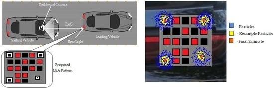
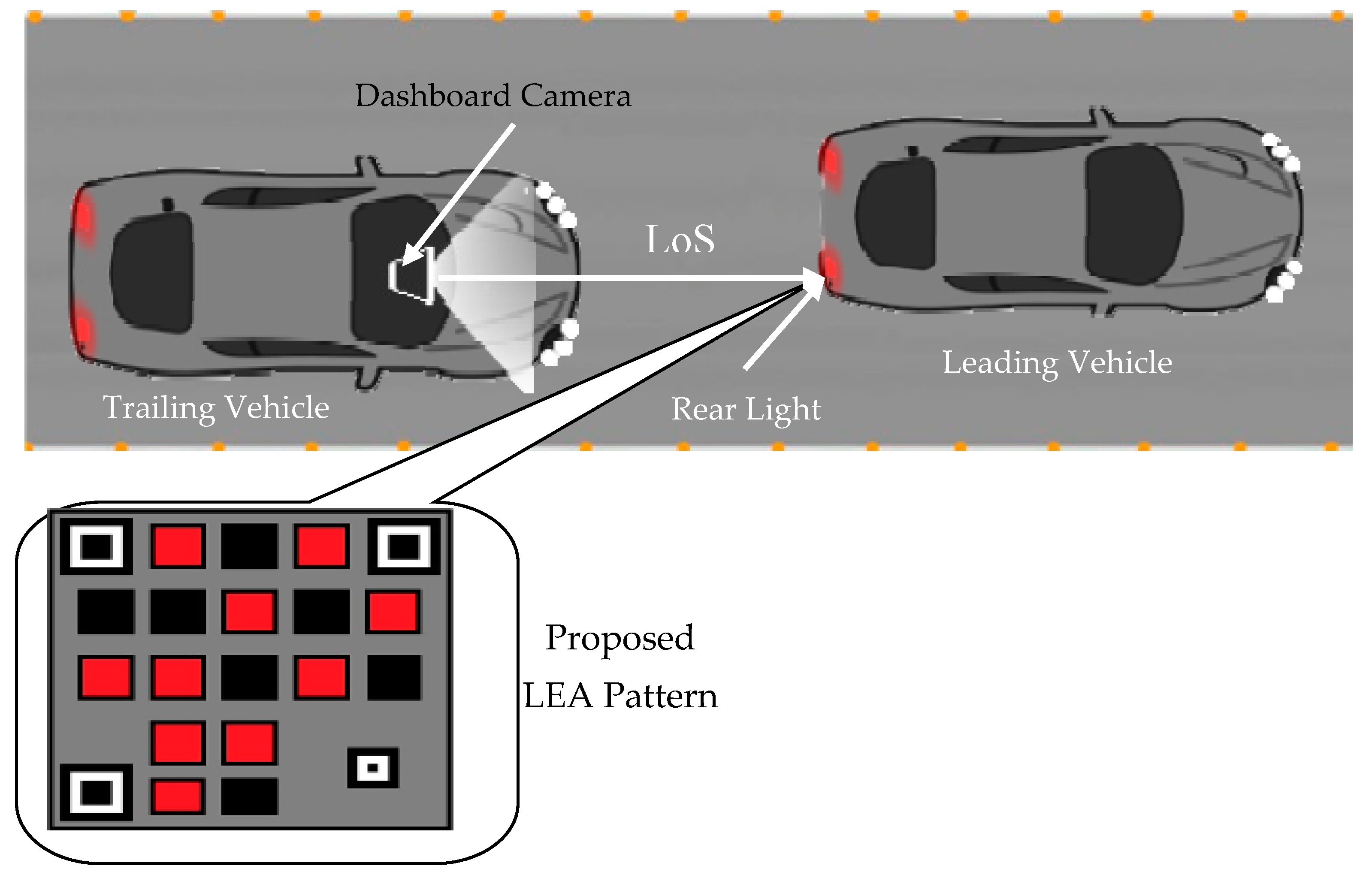
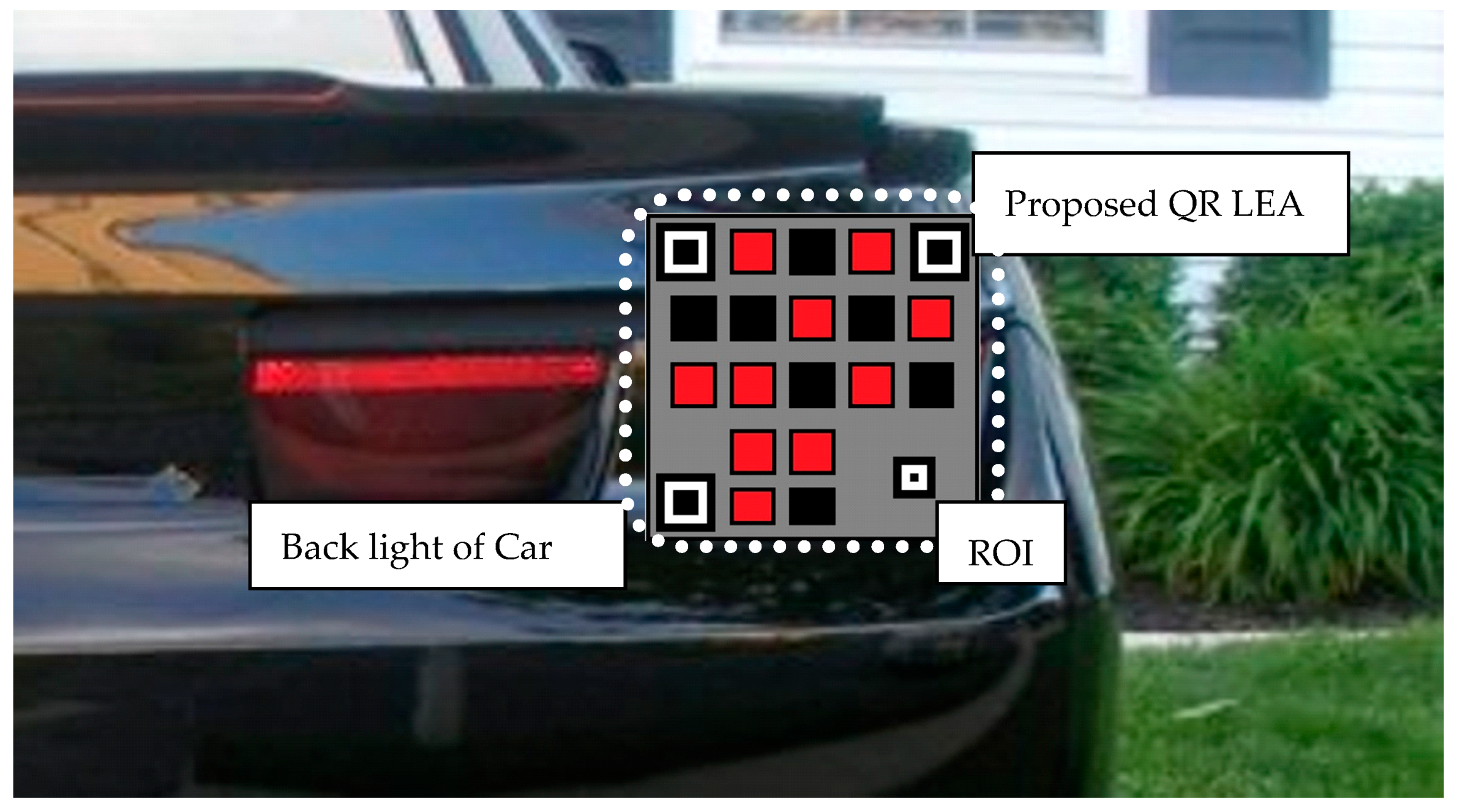
The secure visual MIMO communication system setup proposed for the security vehicular network (SVN) is illustrated in
Figure 1. It uses an existing dashboard camera of the trailing vehicle and rear light of the leading vehicle as a receiver and transmitter, respectively. The leading vehicle transmits environmental data acquired from exteroceptive sensors, vehicles internal parameters, vital biological signals of the driver and influential person as an optical signal. Transmission of this optical signal demands LoS. To facilitate the LoS, the rear light is modified with the proposed QR inspired the LEA patterns, and the particle filter is used to track the spatially varying LEA pattern.
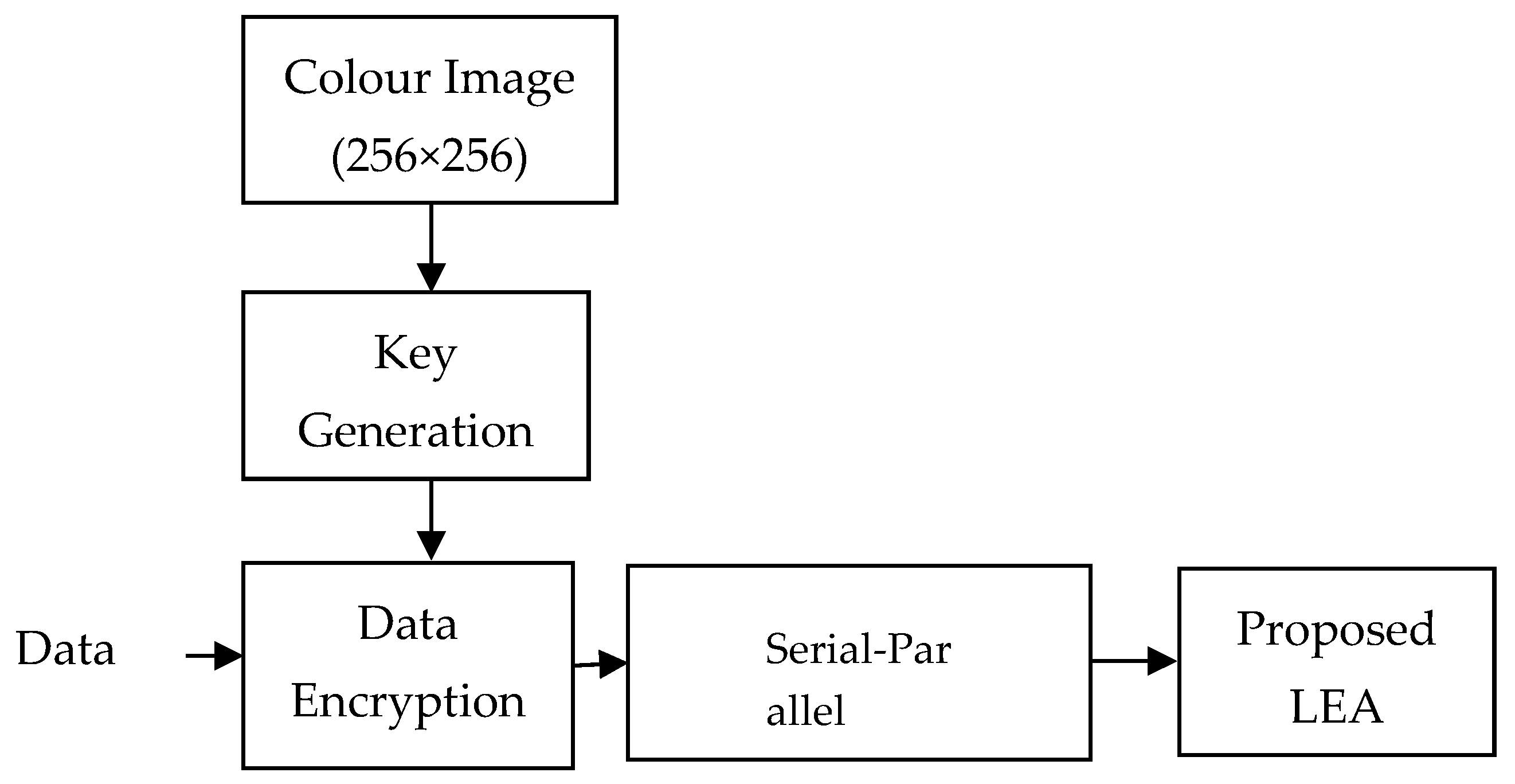
In the transmitter section at the leading vehicle as illustrated in
Figure 2, data is encrypted by stream ciphers using the proposed LFSR based random key generation. The keys are generated using the synthetic color image stored in the database. The encrypted data is converted into a parallel form and given to the proposed QR inspired LEA setup.
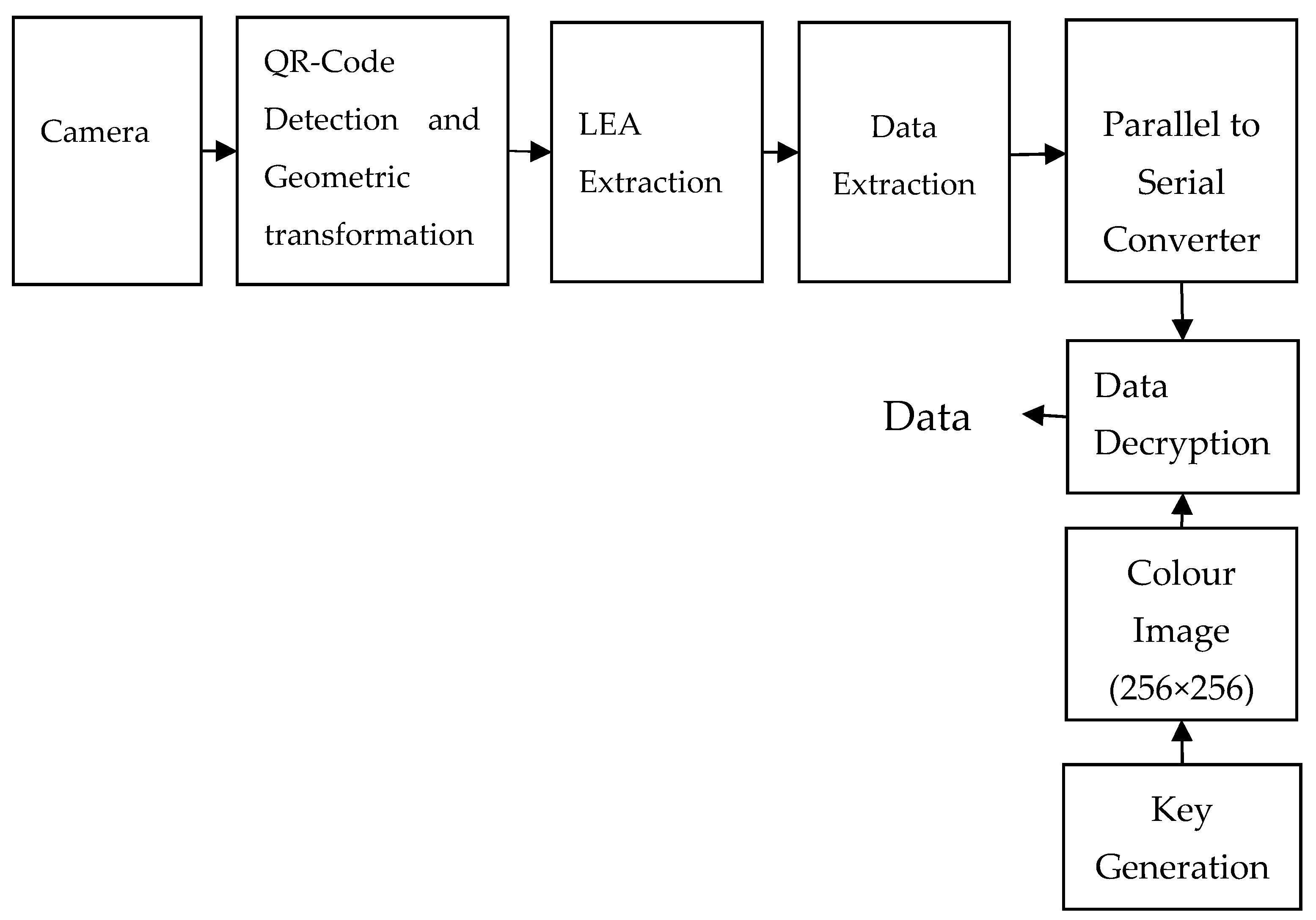
At the receiver section, the proposed LEA setup is captured by the camera at the trailing vehicle and further processed as shown in
Figure 3. The finder and alignment patterns of the QR-Code are detected to extract the region corresponding to the LEA. Geometric transformation is applied for rectifying the distortions, and the original image is reconstructed. Each LED from the LEA is segmented, and data is extracted from the LED using a threshold value. Then, the extracted data is given to the serial to parallel converter and decrypted using the proposed key generation algorithm. Finally, the original data is retrieved from the encrypted data.
2.1. LFSR Based Key Generation
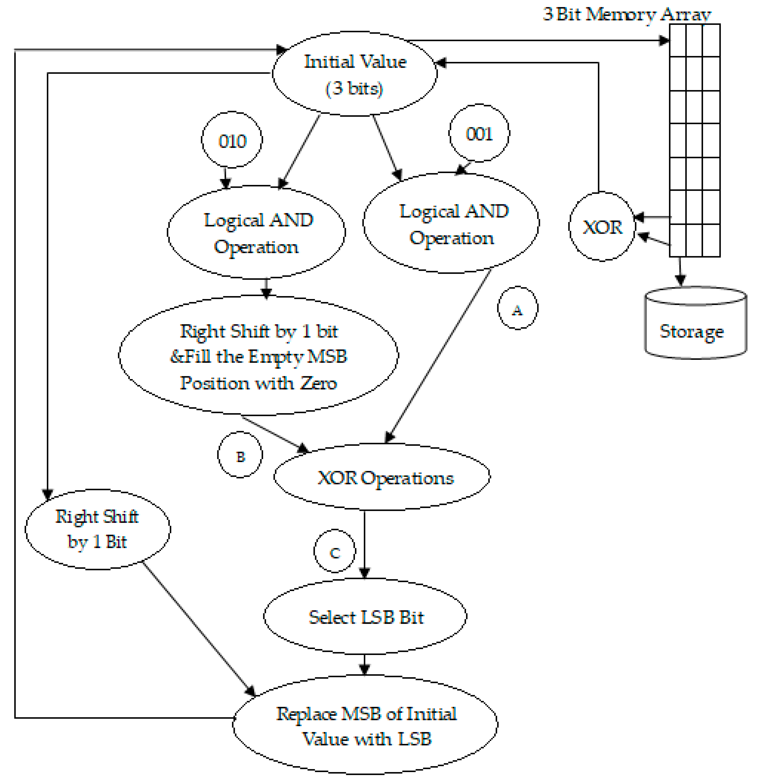
The steps for generating various sequences using LFSR (Ref
Figure 4) are given below.
- Step 1:
Select a three-bit of initial value randomly except all zeros.
- Step 2:
AND the initial value with ‘001’ and get the result. Let this be A.
- Step 3:
AND the initial value with ‘010’, and right shift the result by one bit. Next, fill the empty MSB of the result with ‘0’. Let this be B.
- Step 4:
XOR A and B. Then extract the LSB of the result and set as C.
- Step 5:
Right shift the initial value by one bit and replace the MSB of the result with LSB of C. This gives new three-bit value.
- Step 6:
Store the new three-bit value in an array. Consider this three-bit value as an initial value.
- Step 7:
Repeat from step 2 to step 6 until seven different three-bit values are stored in an array. These seven values are considered as a sequence.
- Step 8:
XOR last value and penultimate value in the array. The obtained result is considered as an initial value for the next sequence.
- Step 9:
Repeat from step 2 to step 8 until seven different values are generated with seven different initial values.
- Step 10:
All these sequences are stored in a memory array.
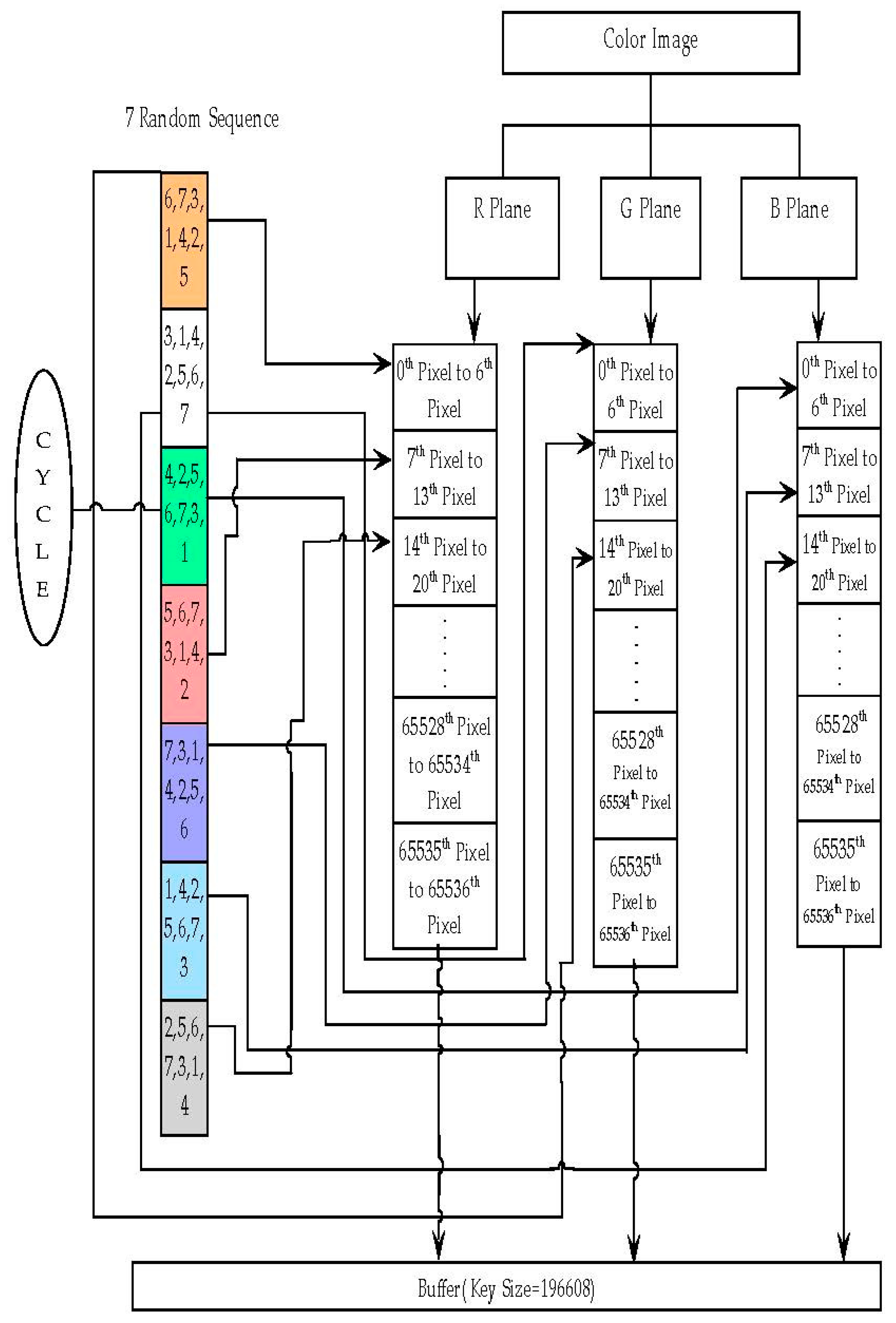
The steps involved in generating a random key using the LFSR based key generation (Ref
Figure 5 for flow chart representation) are given below.
- Step 1:
Get the color image of size 256 × 256 as illustrated in
Figure 6. Divide the selected image into three layers red, green, and blue.
- Step 2:
Select the red layer. Each pixel in the red layer is represented by eight bits.
- Step 3:
Select the first sequence in the memory array. The elements in the sequence are considered as the bit locations of the eight-bit pixels.
- Step 4:
Extract bits from first seven pixels of the red layer based on the bit locations in the first sequence and store the extracted bits in a buffer.
- Step 5:
Select the green layer and the next sequence in the memory array. Extract bits from first seven pixels of the green layer based on the bit locations in the second sequence and store the extracted bits in another buffer.
- Step 6:
Select the blue layer and the next sequence in the memory array. Extract bits from first seven pixels of the blue layer based on the bit locations in the third sequence and store the extracted bits in another buffer.
- Step 7:
Select the red layer and the next sequence again and repeat step 4 for the next seven pixels. Concatenate the obtained seven bits with the stored buffer.
- Step 8:
Similarly, repeat for the green and blue layers. If the previous sequence is the last sequence in the memory array, then the next sequence is the first sequence in the memory array.
- Step 9:
Repeat step 7 and step 9 until all the pixels are used for the bit extraction.
- Step 10:
This results in three buffers for the red, green and blue layers. Concatenate these three buffers and the result is considered as the generated key.
2.2. Detection and Tracking Algorithm
The flow chart for the QR inspired LEA detection is represented in
Figure 7. The steps involved in the detection process are given below.
- Step 1:
Acquired the image using the camera attached at the front end of the secondary vehicle.
- Step 2:
Convert the captured color image into a grayscale image.
- Step 3:
Use a median filter to remove the noise effect created by the ambient light.
- Step 4:
Convert the filtered grayscale image into a binary image.
- Step 5:
The binary image is scanned for the finder pattern of the QR-Code with a pattern scan ratio of 1:1:3:1:1 throughout the image. The respective center points of the three finder pattern are obtained by scanning. Similarly, the alignment pattern is determined with the pattern scan ratio of 1:1:1:1:1, and the center point of the alignment pattern is calculated.
- Step 6:
Finder and alignment patterns are tracked using a particle filter
- Step 7:
Identify the coordinates of the ROI corresponding to the LEA using the finder patterns and alignment pattern.
- Step 8:
Select the ROI on the grayscale image from Step 2 and perform a geometric transform to retranslate the image to the original dimension.
For Each LED Do,
- Step 9:
Extract the ROI of each LED from the restored image.
- Step 10:
Find the average of the pixel values inside the ROI of the LED.
- Step 11:
Adaptive threshold technique to estimate the status of the LED.
End
- Step 12:
Set the incoming message bit based on the status of the LED from Step 11.
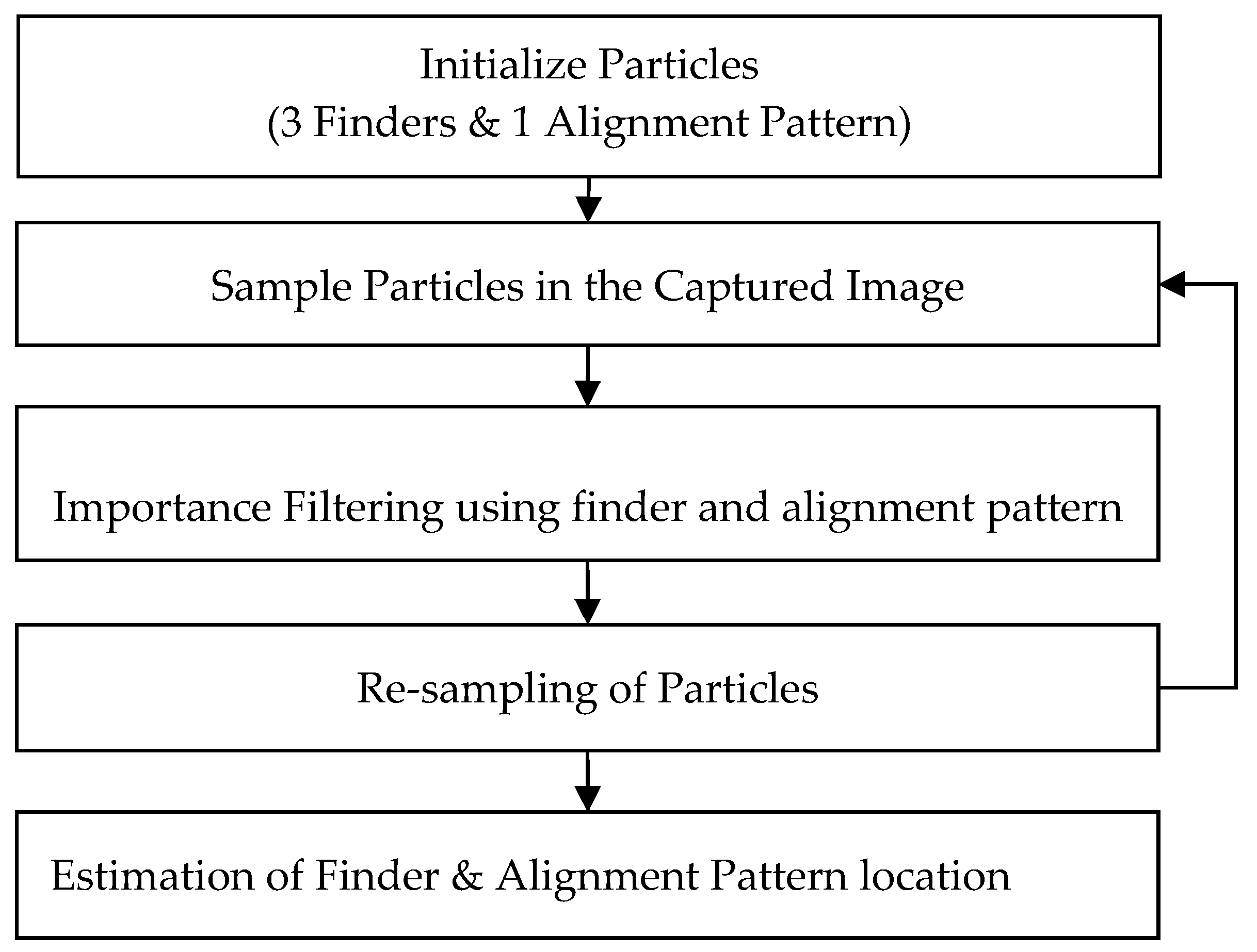
The flow chart for the particle filter tracking is represented in
Figure 8. The steps involved in tracking are given below.
- Step 1:
Initialize the particles for three finders and one alignment pattern of the QR-code.
- Step 2:
Sample these particles in the captured image for three finder patterns and alignment pattern. Initially, the particles are spread randomly over the entire image, indicating the possible location of the QR pattern.
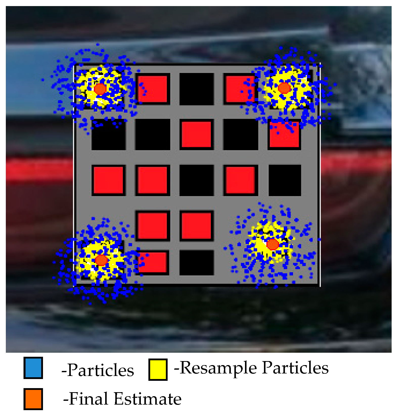
- Step 3:
Apply importance filtering based on the identified pattern scan ratios of three finder patterns and alignment pattern. Importance filtering calculates the weight of all the particles and selects the region that contains particles with large weights.
- Step 4:
Resample the particles inside the estimated regions of finder patterns and alignment pattern as in
Figure 9.
- Step 5:
Estimate three finder patterns and alignment pattern locations from the sampled particles.
- Step 6:
Select the next captured image and repeat from step 2 to step 5 to estimate three finder patterns and alignment pattern.
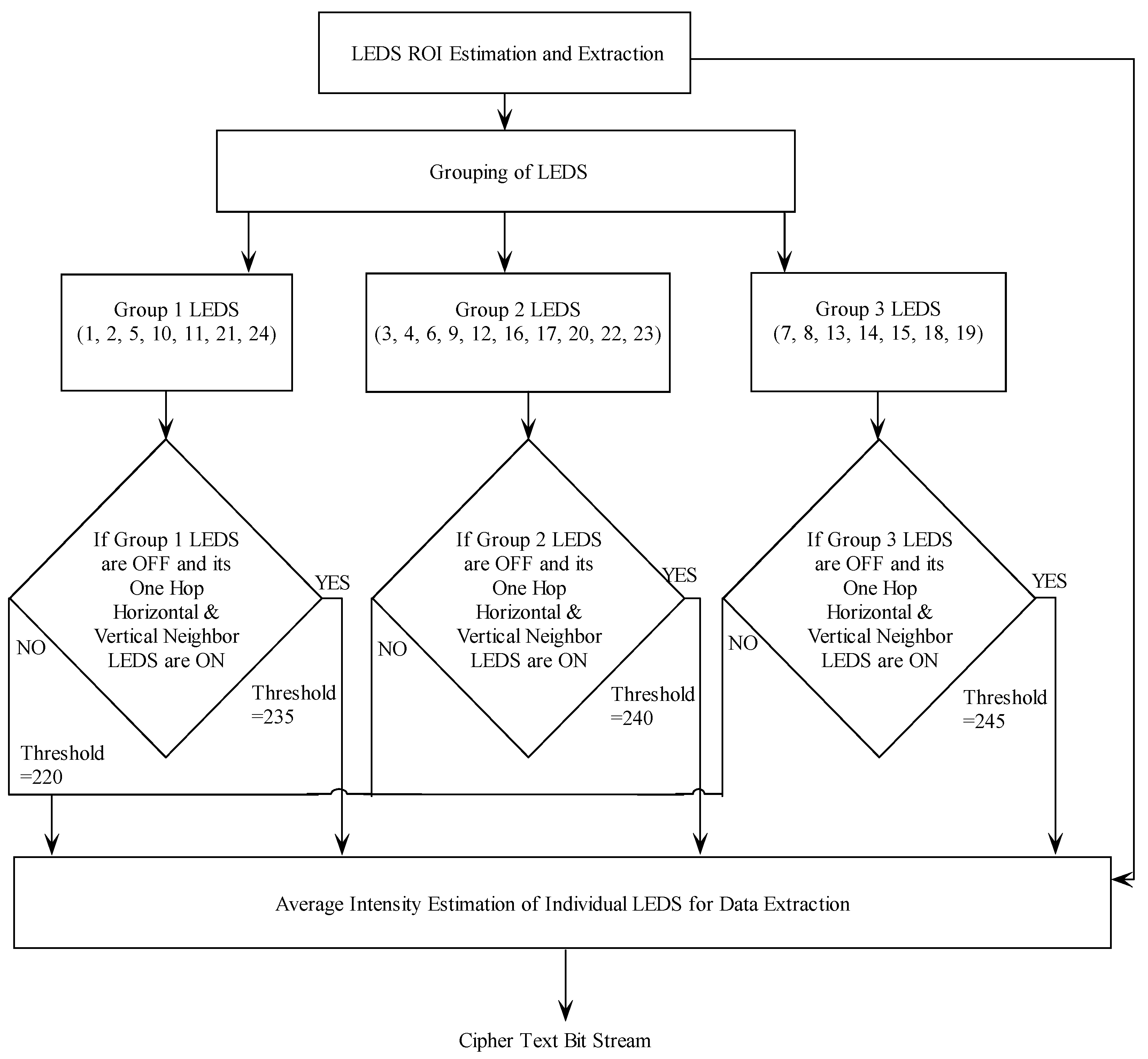
2.3. Adaptive Threshold Technique
In the single input single output (SISO), an optical wireless communication system information is received with a negligible amount of interference. However, in the proposed visual MIMO system, an ambient light and adjacent channel interference degrade the signal to interference noise ratio (SINR), which leads to a significant decrease in the BER performance. This problem can be addressed with the use of an adaptive threshold technique as illustrated in
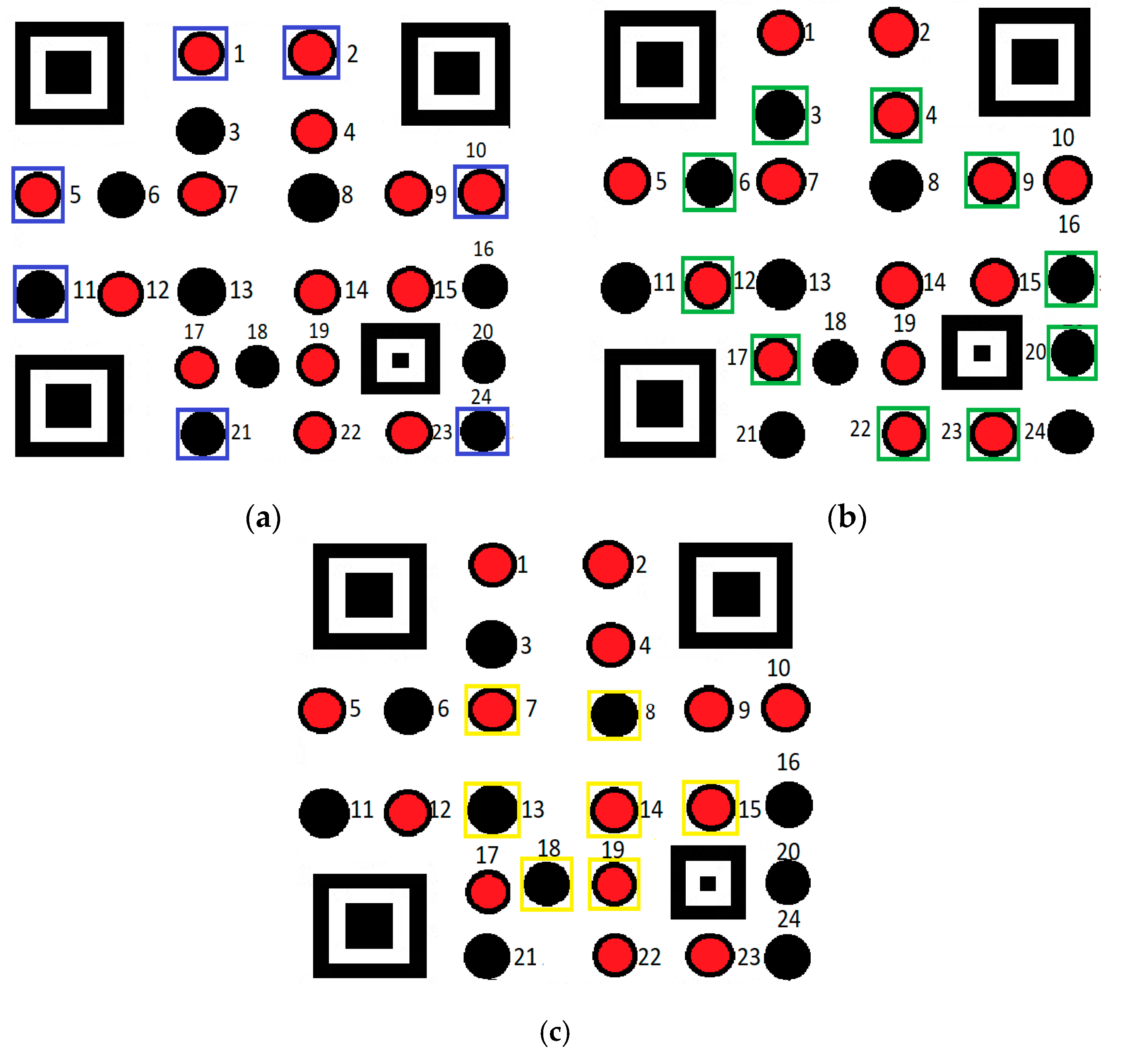
Figure 10. In the proposed technique, the LEDs present in the LEA are divided into three subgroups, namely group-1, group-2 and group-3 based on their spatial distribution. LEDs placed in the interior, intermediate, and outer region of LEA are selected to form group-3, -2 and-1, respectively. The LED subgroups are highlighted with a yellow, green, and blue color marker as illustrated in
Figure 11. This grouping of LEDs provides a reliable tool to minimize the interference created by adjacent LEDs.
The proposed ATT involves two steps. First, estimate the LED status with a fixed threshold and the second step adaptively changes the threshold value based on the adjacent LED status. In the first step, the status of each LED in the LEA is calculated by finding the average intensity of all the pixels belonging to that LED. The status of an LED is determined by setting the threshold value for this average intensity. By experimental analysis, the threshold is set to 220 in the grayscale level in the absence of interference. In the second step, the threshold value for each LED is altered based on the status of its immediate horizontal and vertical neighbor LEDs. If group-1 LEDs are OFF, then the status of their immediate horizontal and vertical neighbor LEDs is noted. If those LEDs are ON, then the threshold is increased to 235 and the status of the group-1 LEDs is corrected. Similarly, a new threshold of value 240 and 245 are set based on adjacent LEDs for group-2 and -3, respectively and their status are corrected.
3. Results and Discussion
The proposed system model is tested in both simulated as well as the real-time environment and its tracking performance is analyzed in the presence of disturbance. The images are subjected to translating, rotating, and scaling perturbations that commonly occurs in the leader-follower configuration. BER is considered as a performance index to evaluate the proposed system in all these scenarios.
Additionally, the LFSR based key generation technique is implemented for secure communication. The incoming data stream is encrypted by stream ciphers using this generated key. The security of the system is evaluated based on the randomness of the key. Various tests proposed by the National Institute of Standards and Technology (NIST) suite are used for determining the randomness of the generated key as listed in
Table 1. These tests predominately measure the probability of the given key. A benchmark of 0.01 is considered for the probability of passing the test. Proportion and probability values are used as performance metrics. It is observed that the key generated using the proposed method has proportion values of 10/10 with the probability value greater than the benchmark (>0.01). These results show that the generated key is random, which is capable of generating a robust cipher stream. In both the environments, the data given to the LEA transmitter is encrypted using the generated random key.
3.1. Complexity Level Estimation
Further, the complexity level of the proposed security algorithm is also evaluated. The LFSR key generation method generates a key of size 196,608. The complexity level of the proposed method is estimated by considering three different scenarios as follows. In Case 1, if the attacker does not know about the LFSR random generation and stored color image, it takes 2196,608 attacks to find the random key. In Case 2, if the attacker knows the color image, each pixel in the red, green, and blue planes is represented by eight bits. So, one bit of the key can be selected from one pixel in eight ways. Therefore, the total number of ways in which a key can be selected from one plane (R, G or B) is 865,536. Thus, the total number of ways a key can be selected from the color image is 3 × (865,536). Case 3 defines the scenarios as if the attacker knows the three-bit LFSR (seven sequences) and a color image, it takes seven! ways to determine each sequence. Therefore, it takes seven × (seven!) ways to determine the sequence and extract the key. The complexity analysis in all these scenarios shows that the proposed key is robust and hard to predict. This makes the proposed algorithm applicable to the secured vehicle to vehicle communication using the visual MIMO.
Moreover, the performance of the proposed security algorithm is compared with the existing techniques [
32,
33,
34]. All these techniques are applied to a single random image to make uniform test conditions. The performances of these techniques are compared based on their key size, keyspace, and time taken for key generation, which describes their strength as in
Table 2. The key size plays a crucial role in cryptographic applications. A key generation algorithm that generates a considerably large key size provides better security. It is observed that the proposed LFSR based key generation technique has a larger key size when compared to the existing technique ([
32,
33]). Although the key size in [
34] is larger, the strength of the algorithm is moderate indicated by its lower-key generation time when compared to the proposed technique. The key space is used to determine the strength of the generated key over brute force attacks. It is observed from
Table 2 that the proposed technique provides a large key size, thus providing a large key space. In addition to that the higher key generation time certifies that the proposed key generation algorithm is strong enough against brute force attacks.
3.2. Simulation Studies of QR-Code Tracking
For simulation studies, the LEA of the transmitter section is developed using a QR inspired LEA. The version 5 QR code is taken as a framework, and 17 LEDs are placed inside the alignment and finder pattern. The colour of the LED status (ON/OFF) and background are chosen appropriately to eliminate mishaps. Minimal clearances between LEDs are also maintained to avoid interference, which minimizes the bit error rate. A background image of a vehicle is chosen, and the proposed LEA pattern is embedded, which can simulate images acquired by the rear vehicle in real-time as shown in
Figure 12. About 1000 frames capable of transmitting 17,000 bits are used for evaluating the performance. The simulation parameters used for the performance analysis of the proposed MIMO system are given in
Table 3.
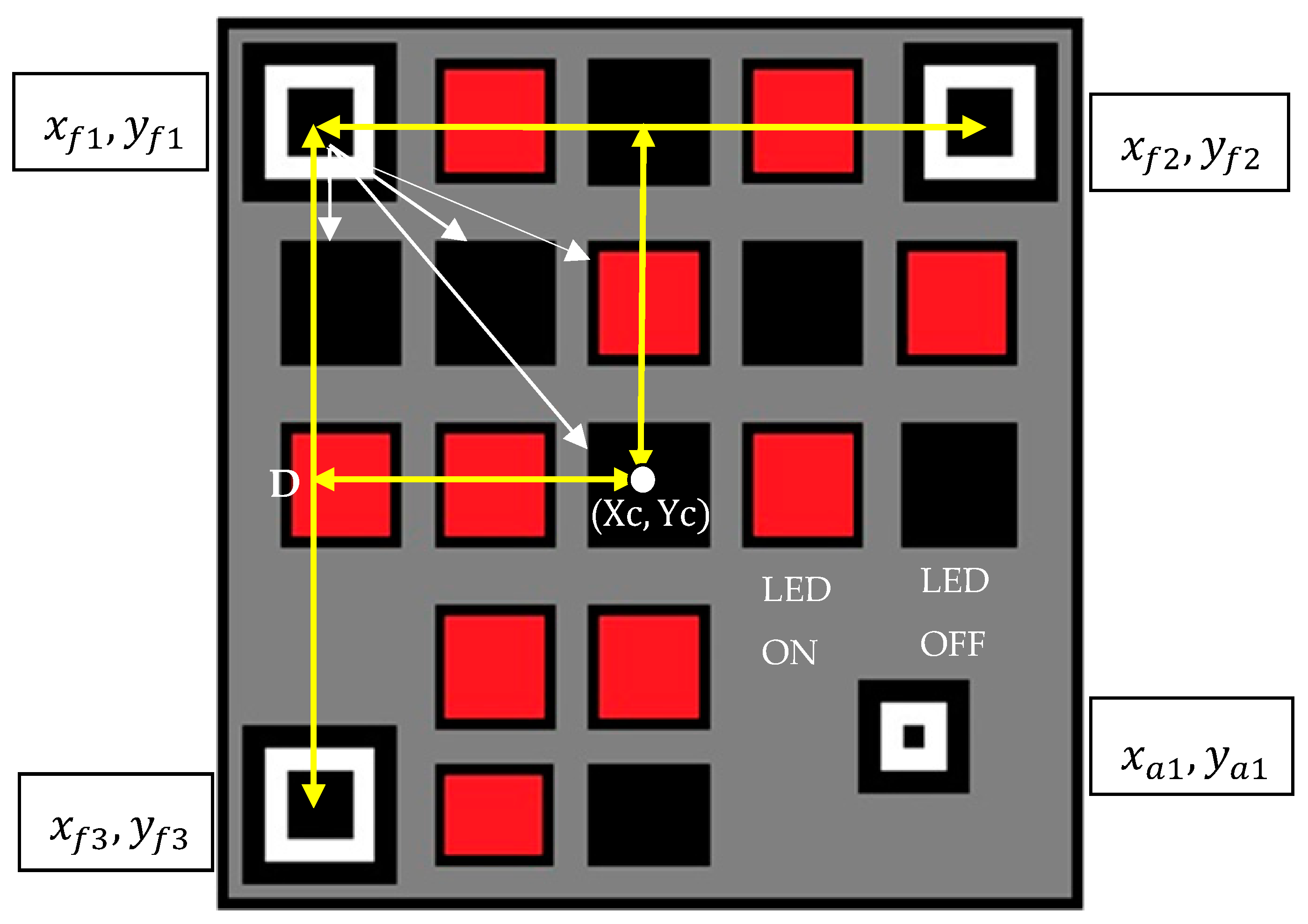
At the receiver section, the finder (
) and alignment pattern (
are detected using the QR code detection algorithm. The detected finder and alignment patterns are used to recover translation and rotational distortions, respectively. The distance between the finder patterns are estimated and using the geometric property (square shape) of the QR code, the center of the LEA
is evaluated as in
Figure 13. The relative scale between the original and detected QR pattern are estimated. As these LEDs are placed in a pre-defined position, the relative scale is used to estimate the position of LEDs with respect to any finder pattern. The area of the LED is also determined using this relative scale. Next, the region corresponding to the LEDs are selected from the grayscale image. A threshold level is applied to the selected region of the LED to extract its status (ON/OFF). If the average intensity of the region is greater than the threshold then the LED status is ON and vice versa. Finally, the LEDs status is converted to the data stream, and the BER is evaluated.
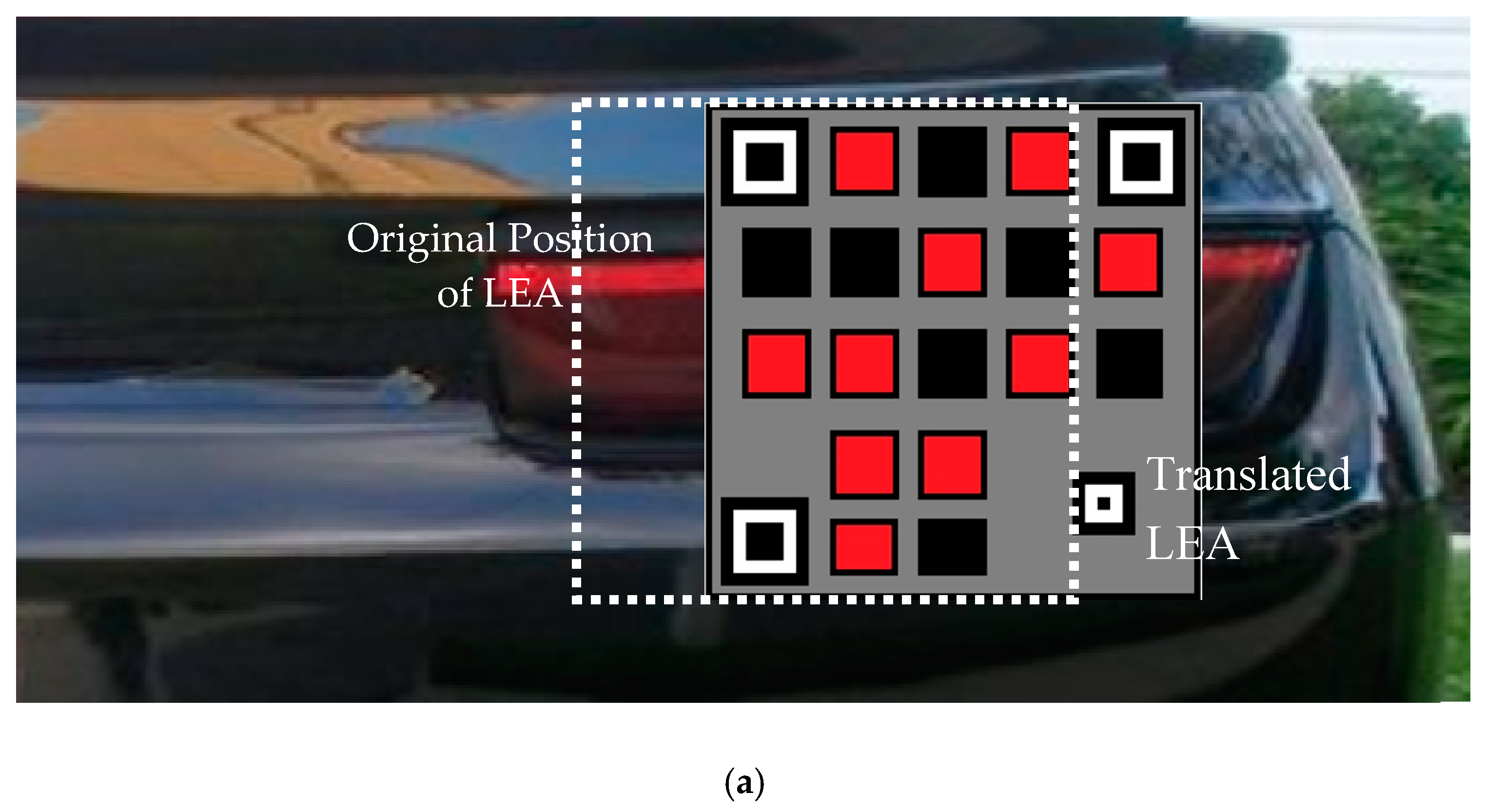
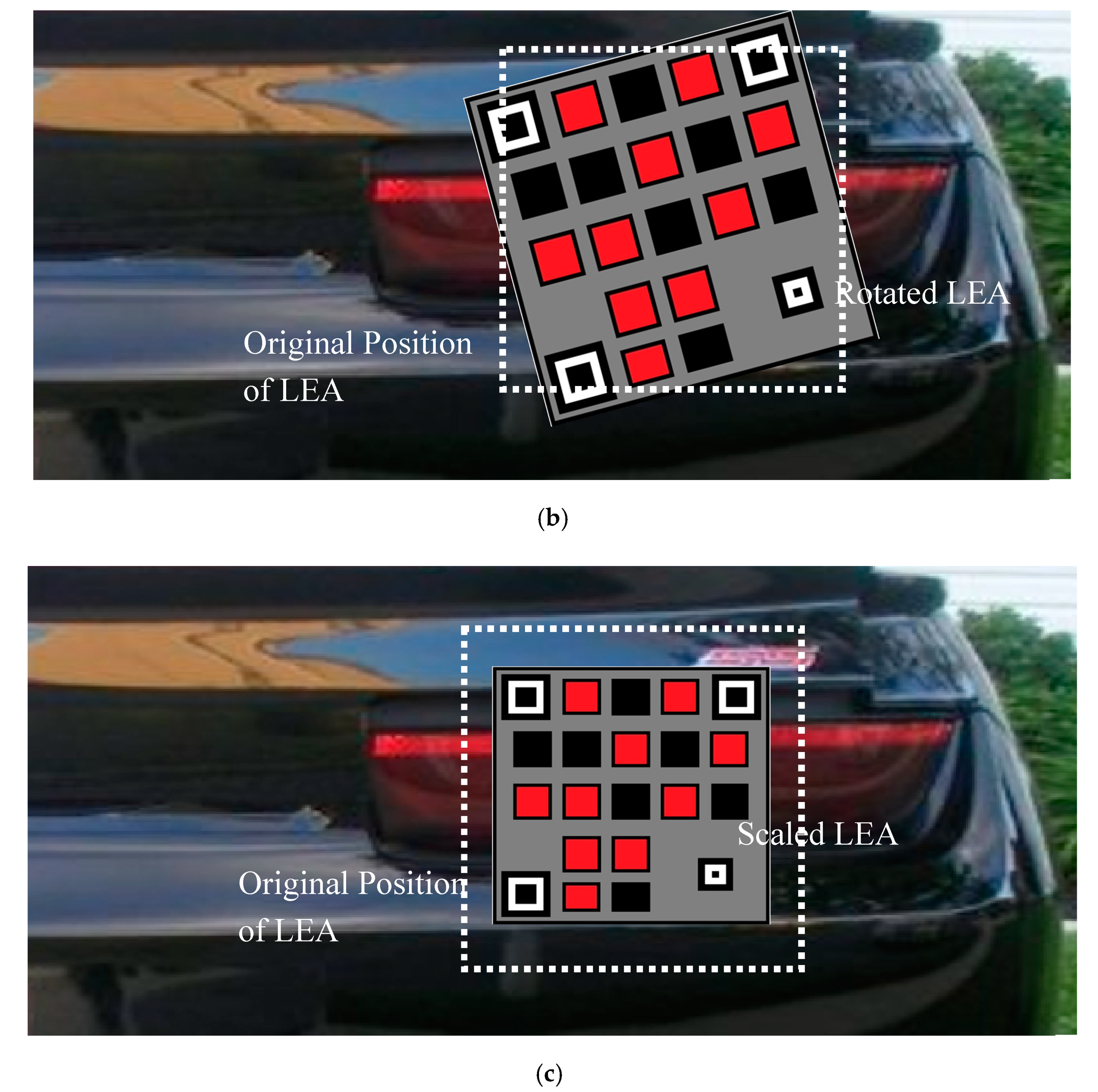
The tracking performance of the proposed QR code with the particle filter is evaluated over translation, rotation, and scaling distortions, as shown in
Figure 14. The horizontal translation of the QR code predominately occurs during the relative positional change of the leader and trailing vehicle as in
Figure 14a. The QR code is rotated along its center in both clockwise and counterclockwise directions to evaluate the detection performance as in
Figure 14b. Image scaling occurs as a function of the distance between the leading and trailing vehicle, as in
Figure 14c. On all these scenarios, BER is considered as a performance metric and compared with the use of the QR code detection algorithm (without particle filter) alone.
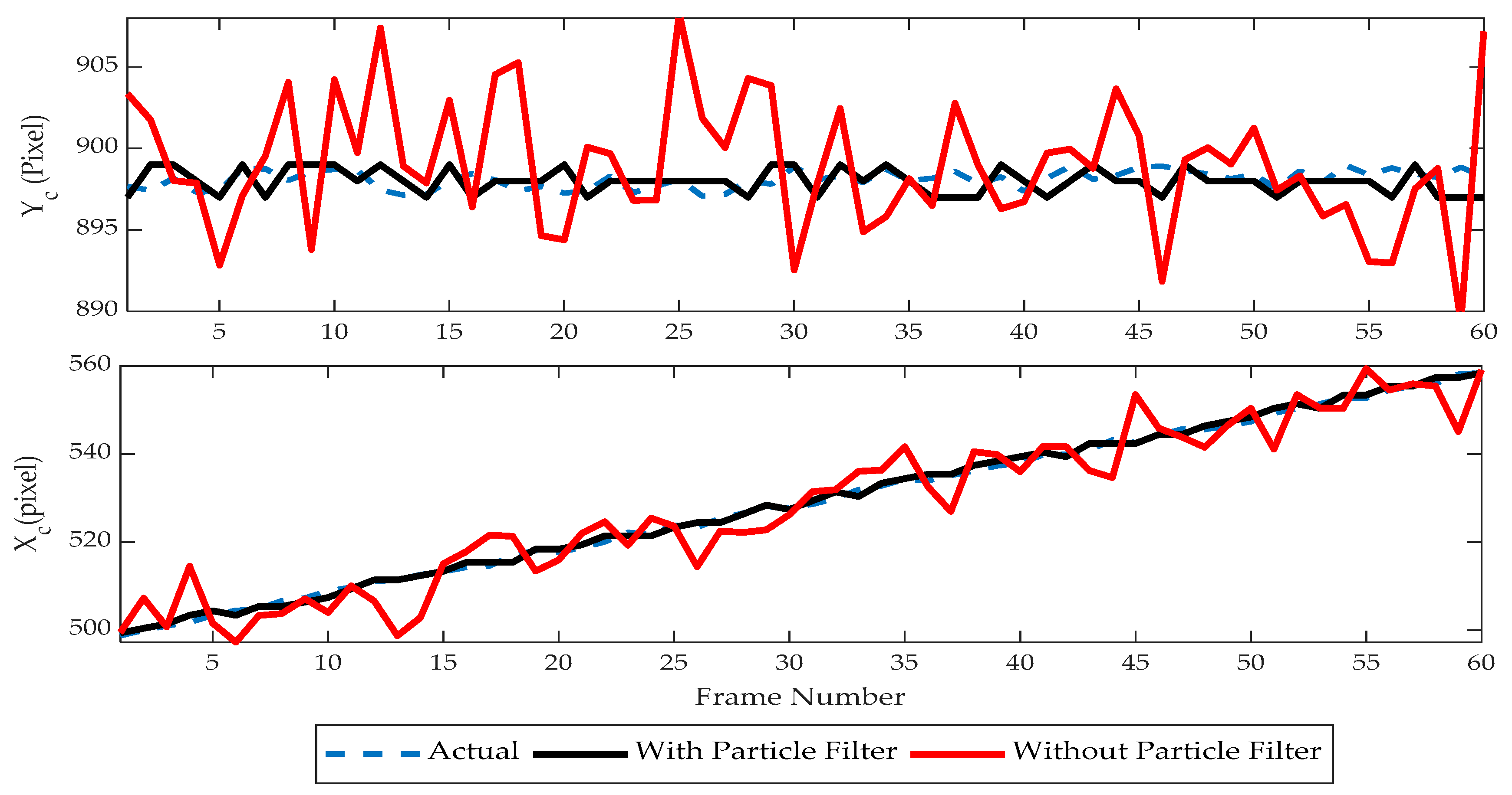
Sixty frames are considered and the center point
of LEA was tracked with and without the particle filter, and its tracking performance was analyzed as in
Figure 15. A horizontal translation at a rate of one pixel/frame is used along with random distortions (five-pixel variance) on both planes to evaluate the tracking performance. The obtained results show that with the introduction of the particle filter; the tracking performance has been improved. Further, the BER performance is studied under a range of geometric noise during translation motion for 1000 frames (No of Bits Transmitted: 17,000). The improvement in the tracking performance is also reflected in BER. BER in the visual MIMO communication has been significantly reduced with the use of the particle filter as in
Figure 16.
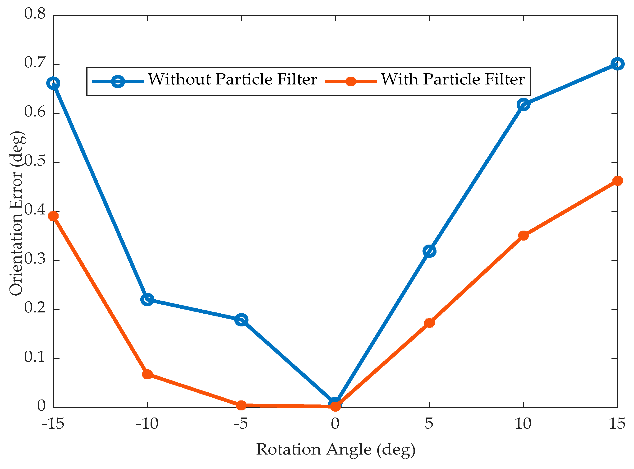
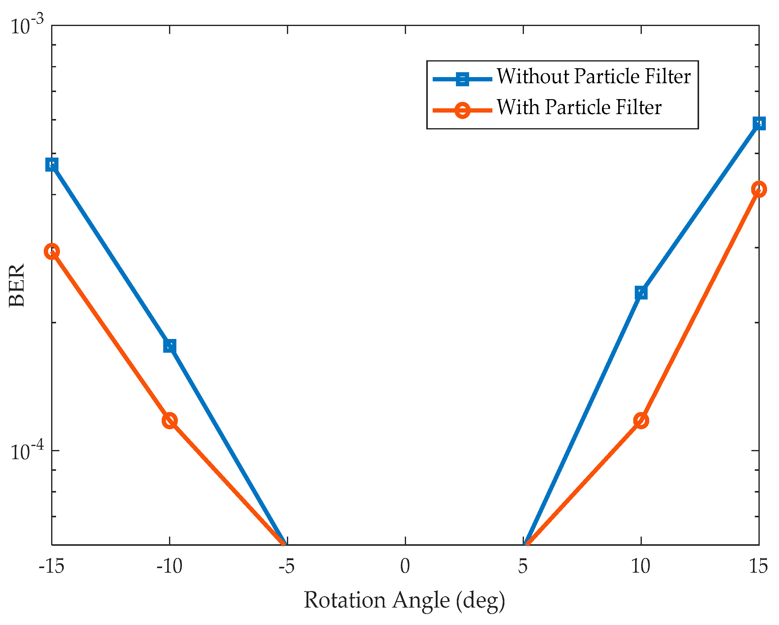
As rotation distortions don’t contribute to a change of the LEA center, it is complex to evaluate their tracking performance. However, the QR code algorithm is capable of estimating the orientation using the detected finder and alignment pattern. This estimated orientation is used to reproject the detected QR code to its original position. Thus, the orientation error can be evaluated by using this estimated and actual orientation.
Figure 17 illustrates the orientation error that occurs with and without the particle filter for images rotated in a clockwise and counter-clockwise direction by an angle of five degrees. It is observed that the particle filter tracking algorithm produces less BER than the system without the particle filter. The BER performance of the proposed detection and tracking algorithm over the rotational distortion is given in
Figure 18. Since the QR code itself is highly robust for the rotational variance, the BER is nullified for five degrees of rotational distortions on both systems (with and without particle filter). No significant contributions have been observed with the use of the particle filter. The QR code itself is efficient in handling the rotational variance.
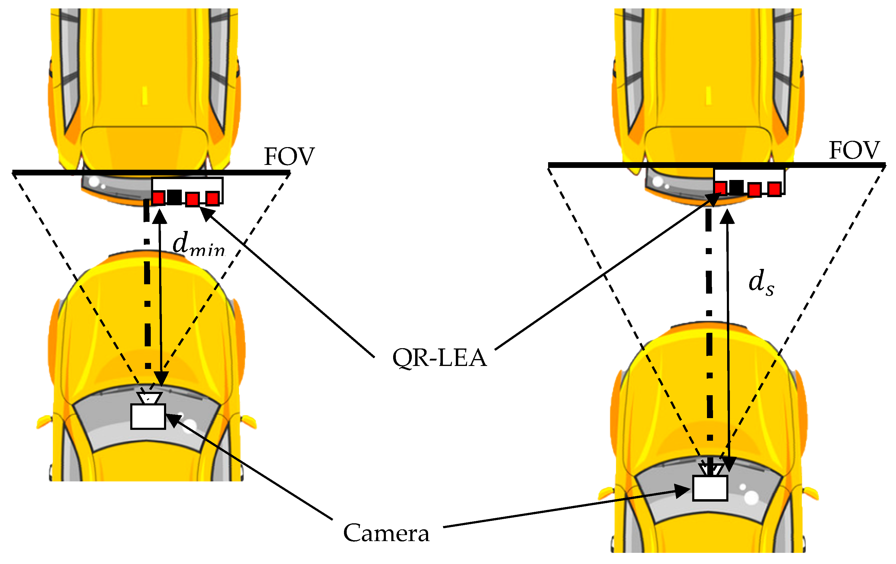
The field of view (FOV) representation of the proposed system model is given in
Figure 19. FOV is defined as the coverage area that is captured by the camera lens. The proposed system uses a constant FOV camera lens instead of an adjustable FOV camera lens. This produces a change in scale variations of the QR code as a function of the relative distance between the vehicles
. The image of the QR code acquired by the camera, when the vehicles are at minimal proximity
is considered an original image with the scale factor as one. With this benchmark, the images acquired at a relative distance
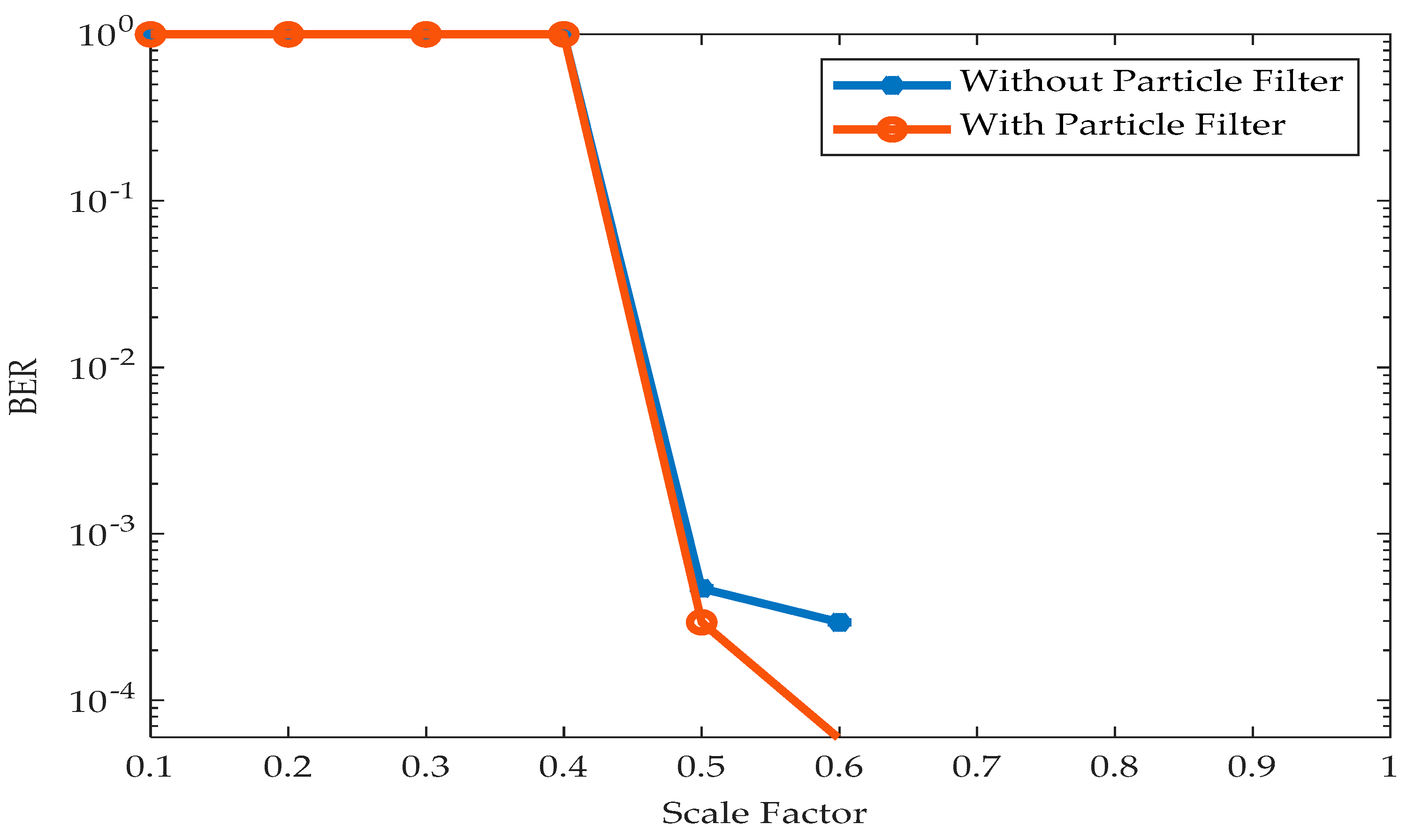
are scaled in accordance (scale factor < 1). The BER performance of the proposed system over an increasing relative distance between the transmitter and receiver is given in
Figure 20. It is observed that the proposed tracking algorithm produces negligible BER up to a scale factor of 0.6. This indicates that the QR code is detected even when the image is compressed by 40%. However, the QR code became undetected after the scale factor of 0.4 and elevated BER is observed.
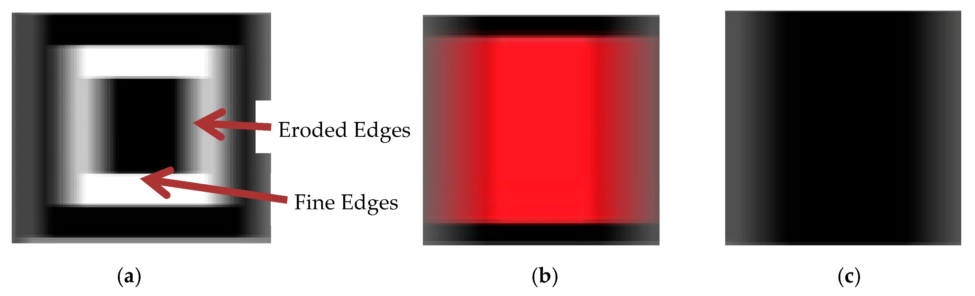
Motion blurs often occurs during the higher relative motion of the transmitter and receiver vehicles. It can also occur due to vibrations created by the uneven road conditions. This makes a blur to occur predominately in the horizontal direction as shown in
Figure 21. Hence, it is necessary to analyze the performance of the proposed system in the presence of motion blurriness. The images are blurred according to the various blur ratios (
and the BER for these images are evaluated. The blur ratio is a measure of the number of pixels blurred (
) with respect to the size of the QR-LEA (
) in the blurred direction as in (1). To simulate the real-time environment, the acquired images are blurred for various pixel values in the horizontal direction (
), which makes the QR-LEA size to be its horizontal length, i.e. 450 pixels (Ref
Table 1).
Figure 21 illustrates the blurred finder pattern of the QR-LEA for a length of 10 pixels. It is observed that the vertical edges are degraded and the algorithm may fail to detect these patterns.
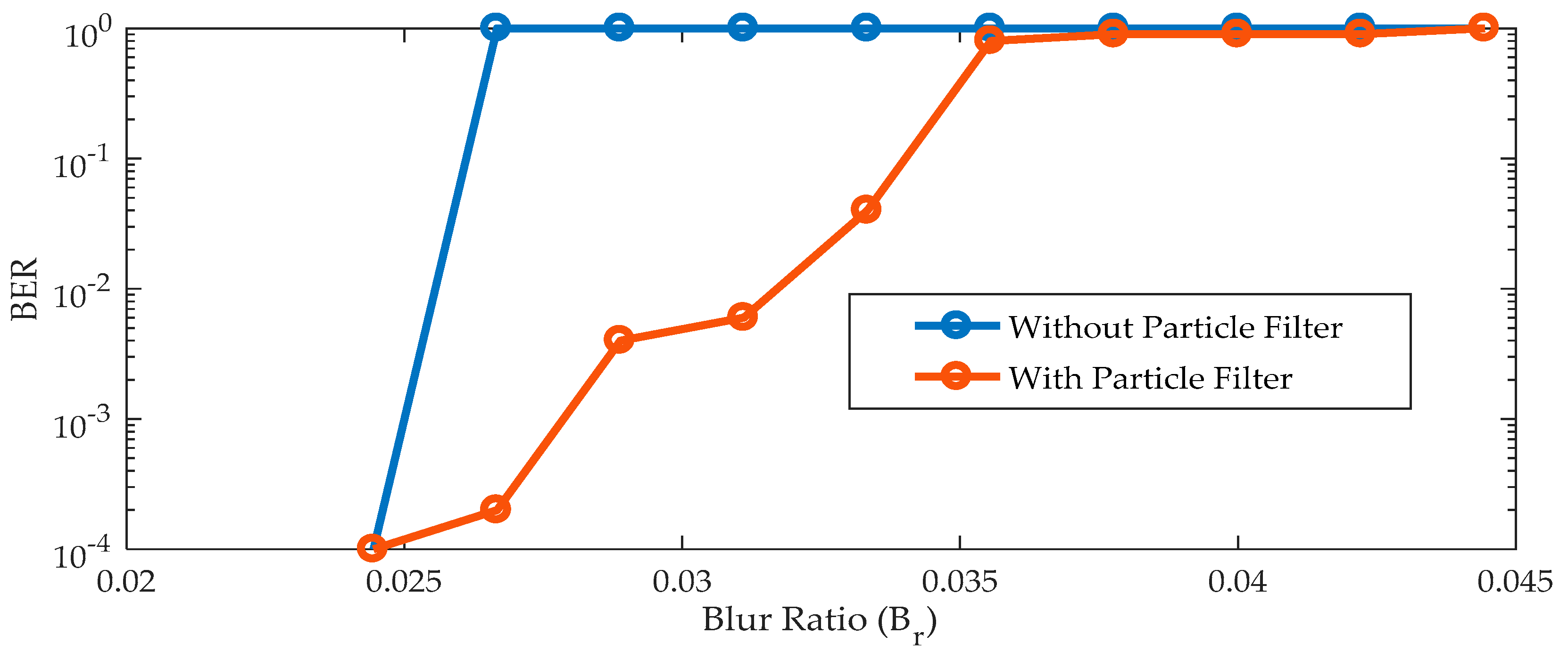
The BER performance in the presence motion blurriness is evaluated with and without the particle filter as in
Figure 22. It is observed that the algorithm fails to detect the finder pattern of the QR code beyond the blur ratio of 0.025. This leads to a loss of communication and increases the BER to one. However, the use of the particle filter can be compromised for this mission detection. It can predict the likelihood of these finder patterns using their past or initial conditions. This enables reliable communications with minimal BER. As the blur increases, the intensity of LEA degrades, leading to a gradual increase in BER. Though the particle can predict the LEA location, degradation in the LEA intensity at higher blurriness leads to communication loss.
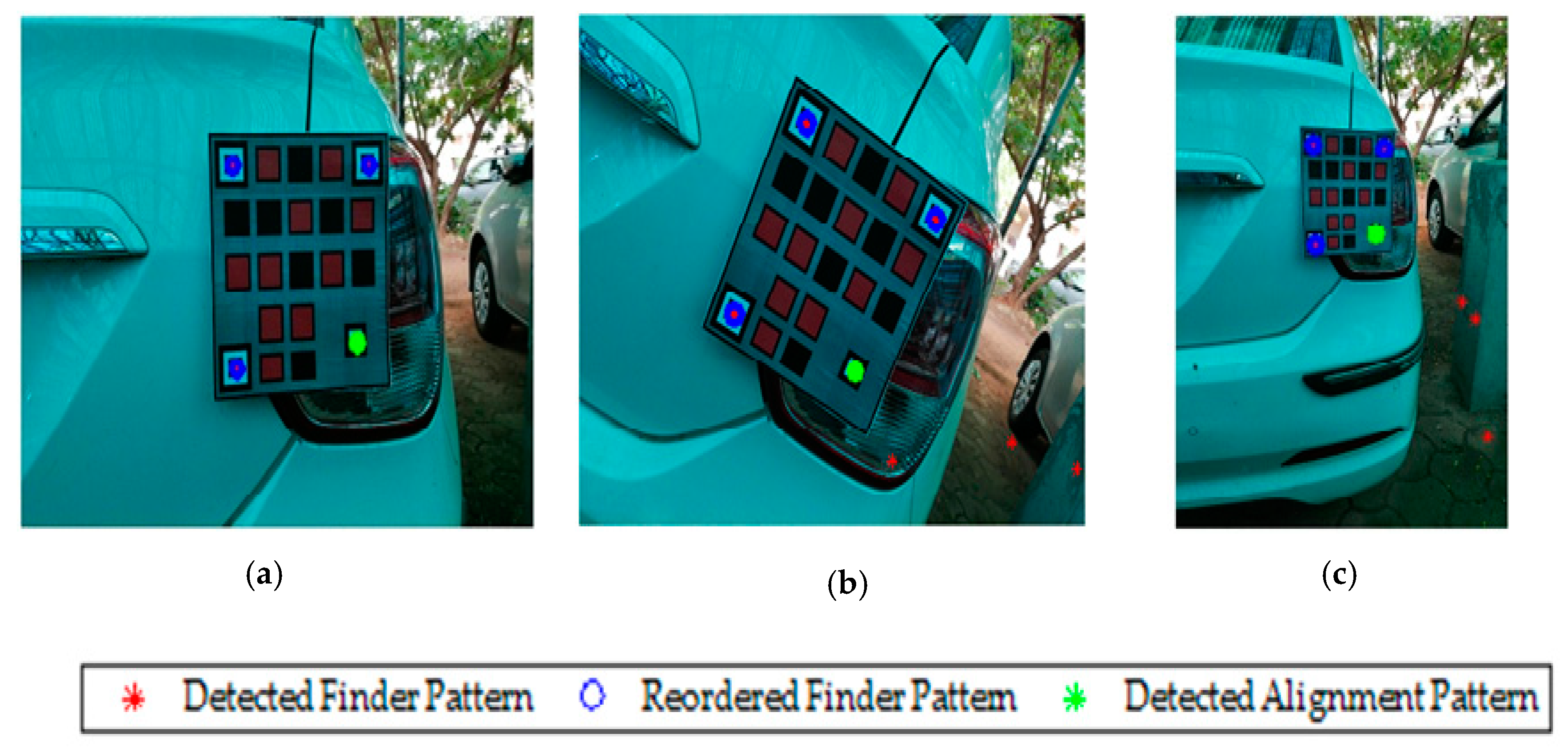
The proposed QR-LEA pattern is fabricated and installed in the rear side of an actual car. The images are acquired from the trailing vehicle in the presence of the translation, rotation, and scaling variance. The range of translation is confined to the FOV of the camera, and the rotational angle is limited to 15-degrees. To ensure continuous detection, the position of the camera is adjusted to set the scaling factor above 0.5. The performance of the proposed tracking algorithm is evaluated in a daylight condition with geometric noise introduced by the ambient outdoor environment. The proposed technique detects all the possible locations of the finder pattern that satisfies the finder pattern ratio. Unlike the synthetic image, it is observed that false finder patterns are observed (ref
Figure 23b). However, the geometric constraint of the QR code enables reordering of the finder pattern eliminating the false detection and capable of accurately tracking the QR code. Accurate detection of the finder pattern enables easy identification of the alignment pattern, which can be used to retranslate the QR-LEA. This makes the proposed algorithm efficient to track the QR-LEA admits camera non-linearity and color mixing.
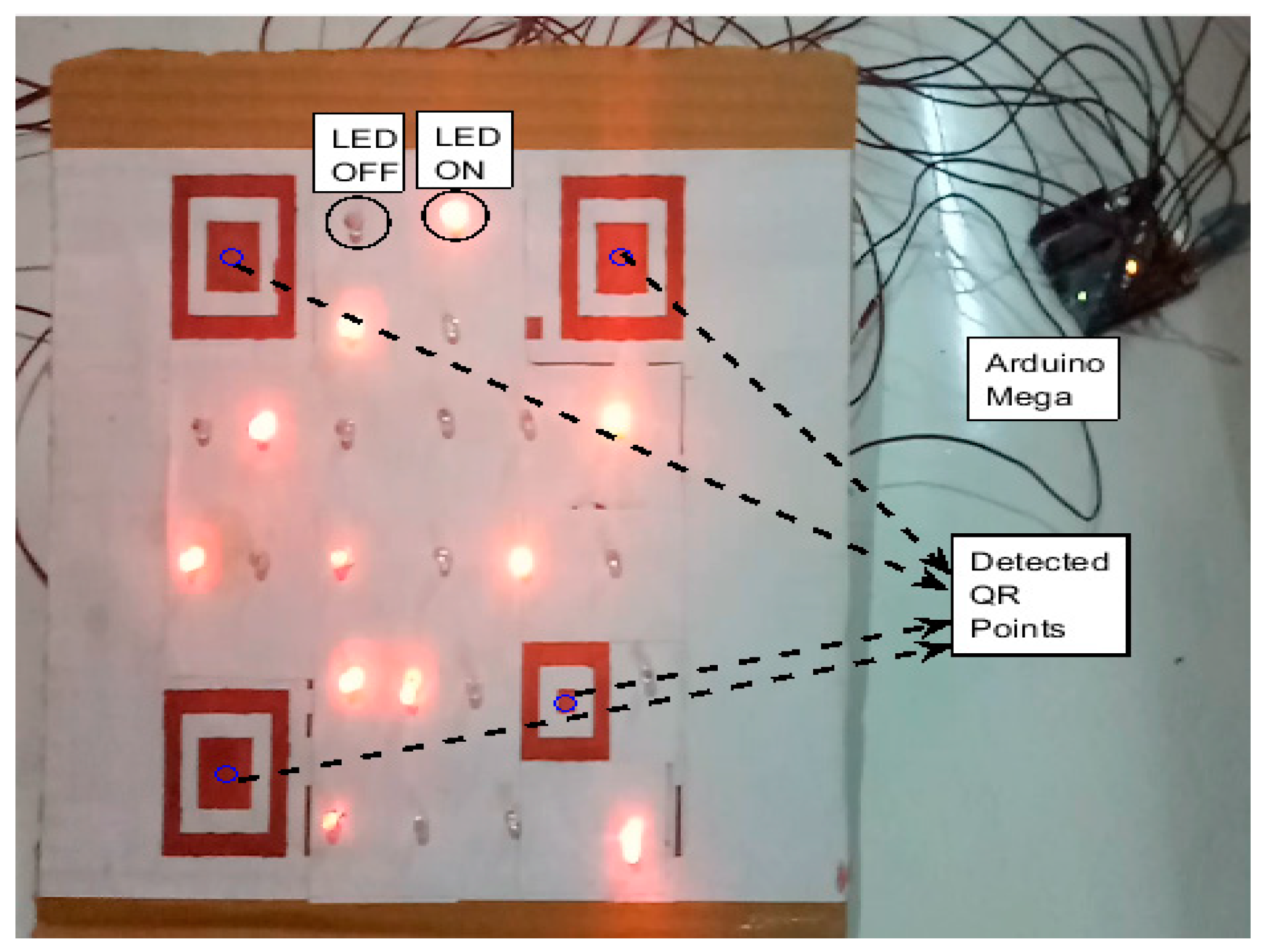
3.3. Real-Time Study
Further, the performance of the proposed MIMO system is evaluated in real-time. A hardware model of the QR inspired LEA is developed using the Version 5 QR code. In this setup, 24 LEDs are placed with the finder and alignment pattern by replacing all the data blocks of the QR code. The LEDs in the LEA are orderly placed and a unique background is chosen for minimizing the interference. Finder patterns and the alignment pattern are represented in dark color to isolate from the LEA and background as shown in
Figure 24. The parameters used for this real-time study are given in
Table 4. The LEA is controlled by a computer using Arduino Mega. The data stream that needs to be transmitted are encrypted in the computer and sent serially to the Arduino Mega. The Arduino Mega sets the corresponding LED status in accordance with the ciphertext.
A mobile phone camera is used as a receiver to acquire the image of this hardware setup. This image is used to detect the QR code and subsequently the LED status is detected using the adaptive threshold technique. This adaptive threshold technique is capable of providing compensation to the interference due to the ambient and adjacent light intensity. The LED status is used to obtain the ciphertext and decrypted using the stream cipher technique with the proposed key.
The real-time setup is tested over distortions in the translation, rotation, and scaling motion as follows. The camera is mounted in the distance to cover the entire region of the QR-LEA pattern. The QR-LEA is kept stationary, and the receiver camera is distorted to emulate the inter-vehicle communication. The camera is moved randomly in both the x and y plane to create the translation distortion. It is ensured that the QR-LEA is visible within the FOV at each frame. The camera is rotated about ±15-degrees, and the QR-LEA images are acquired. The orthogonal distance between the camera and the LEA is adjusted to incorporate scaling. It is observed that a minimum of 225 × 225 pixel occupancy of LEA (
) is sufficient for detection and tracking. The image size is about 3120 × 4160 pixel (
), which makes the allowable distance between the camera and LEA (
) to be around 2.77 m as in (2). Thus, the physical dimension of LEA and the resolution of the camera determines the allowable distance between the camera and LEA (Scale factor). The BER performance of the proposed system is studied with the dynamic data stream. A pre-defined set of data stream is parallelly fed to the LEDs of the LEA. This dynamic varying LEA is captured by the camera and tracked by the proposed particle filter algorithm. Finally, the observed LEA pattern is decoded to recover the received data stream. This data stream is compared with the transmitted data, and the BER is evaluated.
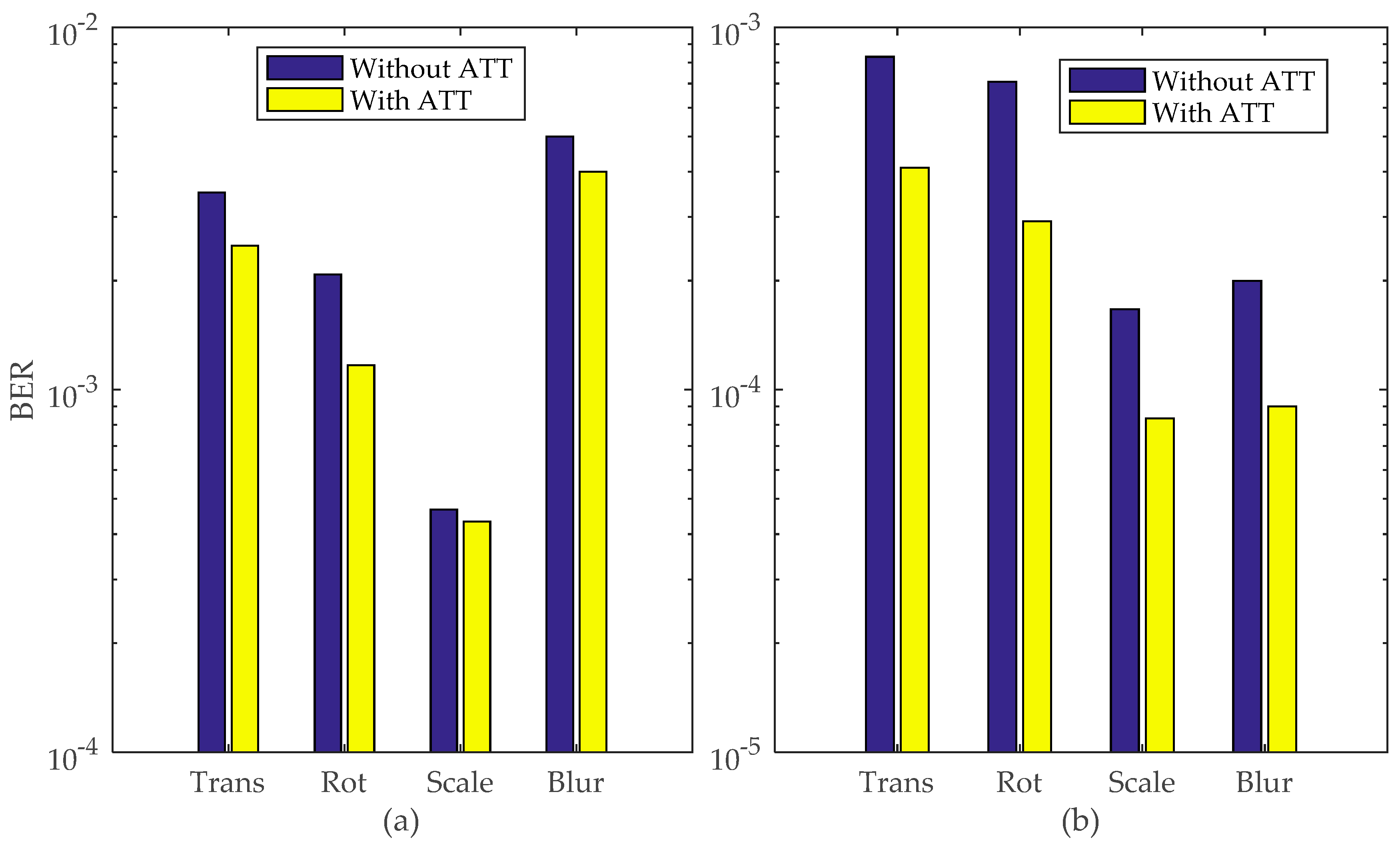
About 1000 frames used to transmit 24,000 bits are considered in this study. The impact of an adaptive threshold technique in the BER performance is evaluated with and without the particle filter. It is observed that the BER performance with the particle filter has been improved as illustrated in
Figure 25. In real-time, the camera is randomly moved to create motion blurriness and to simulate the movement of a vehicle. However, this motion will not blur all the acquired images. The blurred out images may result in missing detection and results in loss of communication without the particle filter. However, the particle filter tends to predict the likelihood location of the QR-LEA and will result in a lossless communication. It significantly improves the BER performances as compared without the particle filter. Further, the performance of the ATT is evaluated and the BER improvement is calculated as in (3) using BER for with and without ATT. It is observed that the BER performance is improved by 49.8% during translation, 58.8% during rotation, 50.3% during scaling distortion and 55.5% during motion blur with the use of ATT along with the particle filter.
4. Conclusions
In this paper, the simulation and real-time setup of the visual-MIMO communicating system has been developed using a novel QR-Code and particle filter tracking algorithms for SVN. The security aspect of the SVN is addressed by a novel LFSR based key generation technique. The key is generated using a random pixel value based synthetic colour image. This key is used in a stream cipher encryption algorithm to generate ciphertext. The randomness test of the generated key exhibits a probability value greater than 0.01 with the least being 0.122 (>>0.01) in the linearity test. The generated key is of 196,608 bit in size, which makes it robust and complex to predict. This makes the proposed system more secure and an ideal candidate for the visual MIMO communication.
The LoS requirement of the visual MIMO is achieved by using the QR-code with the particle filter algorithm. A QR-inspired LEA is designed by embedding LED transmitters with the finder and alignment pattern. The robustness of the QR code makes the identification of LEA more reliable. The particle filter is used for tracking and to maintain the LoS. The proposed system is analyzed in the simulation and real-time environment. The performance of the proposed tracking algorithm is analyzed in the presence of the translation, rotation, scaling, and motion blur distortion. The BER and tracking error are considered as performance metrics. Simulation studies are carried out to analyze the performance of the particle filter based tracking. The results illustrate a better performance as compared to a system without the particle filter.
A prototype of the QR-inspired LEA is fabricated and tested on the real-time environment. ATT has been proposed to compensate the interference generated due to the ambient light and adjacent transmitter elements. The BER performance of the proposed ATT is evaluated in the presence of geometric distortions and results illustrated an average of 53.6% improvement in BER with the use of ATT. Thus, the proposed system is considered as secure and reliable for the visual MIMO communication. The proposed visual MIMO can be extended for a multi-vehicle environment in which the particle can address the associated problem. The use of multi-vehicle communication demands a unique key for each user, and these keys can be generated using the proposed key generation technique.

 ,
, 


