Design of Silica Multimode Optical Fibers with Extremely Enlarged Core Diameter for Laser-Based Multi-Gigabit Short-Range Optical Networks †

 ,
,  and
and 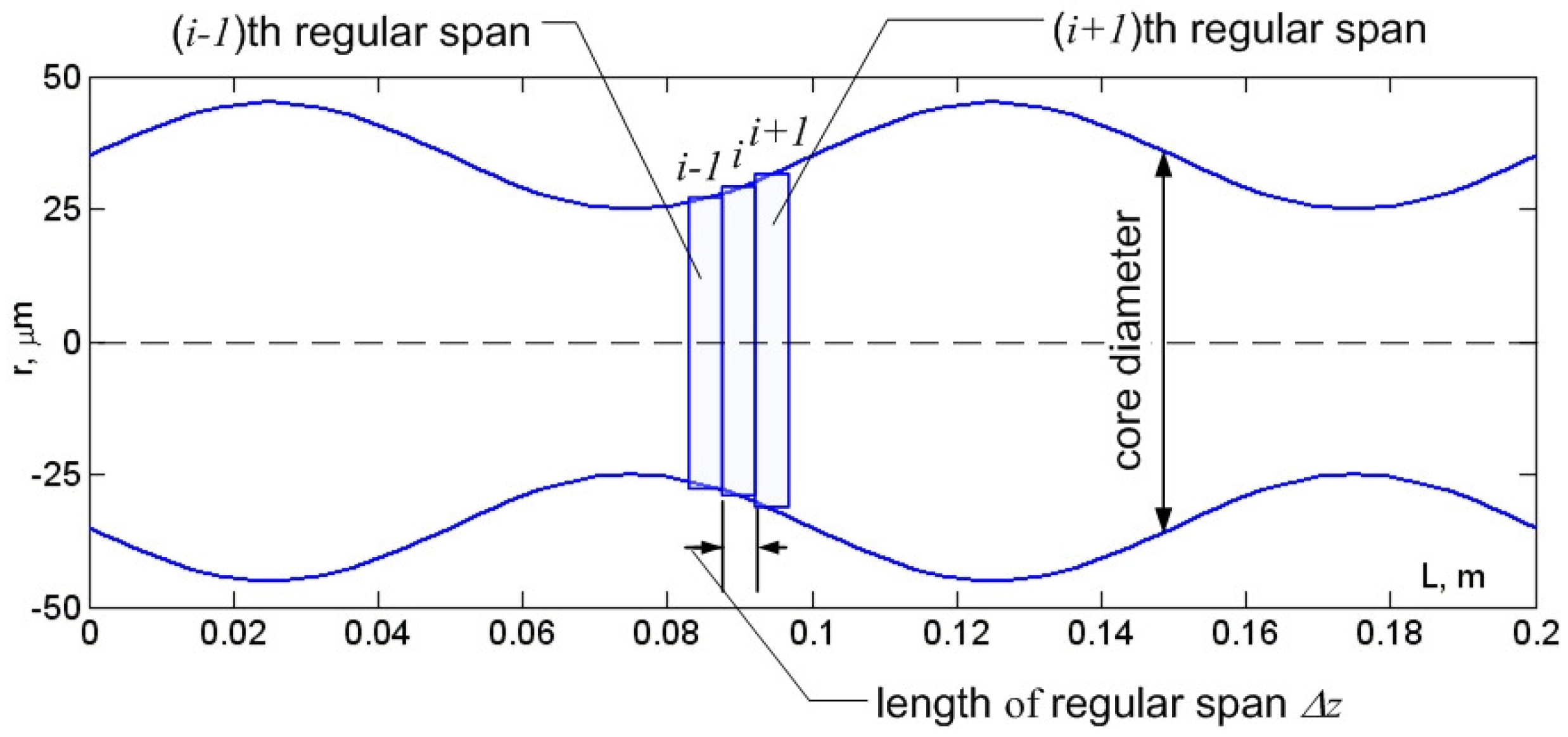
Abstract
1. Introduction
2. Theory
2.1. Related Works
2.2. Design of an LDMDF-Graded Refractive Index Profile
2.3. Extension of Modified Gaussian Approximation
2.4. Mode Delay
2.5. Mode of Chromatic Dispersion Parameter
2.6. Material Dispersion and Refractive Index Profile Parameters
2.7. Model of a Piecewise Regular Multimode Fiber Optic Link Operating in a Few-Mode Regime under Laser-Excited Optical Pulse Propagation
2.8. Mode Coupling
3. Results
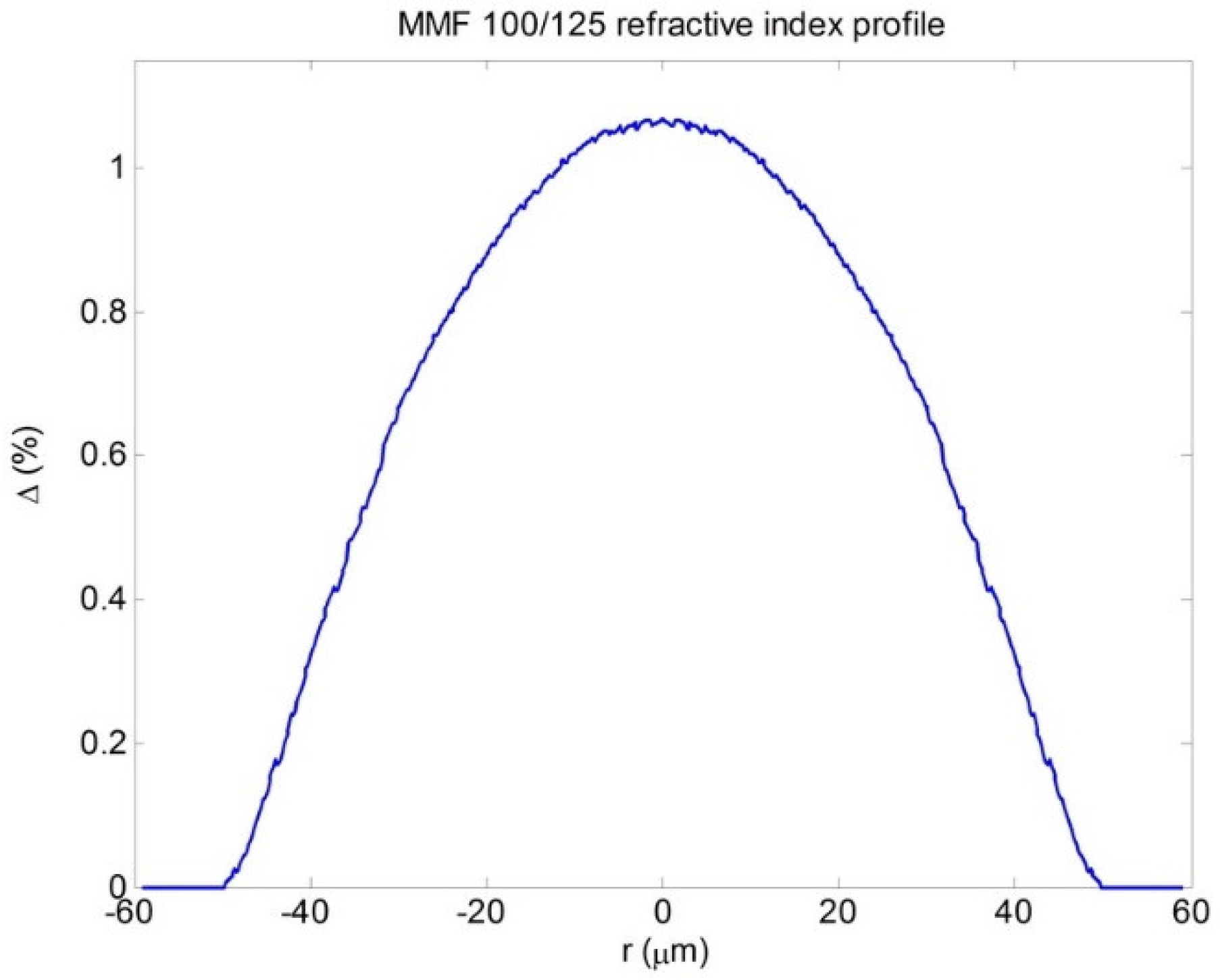
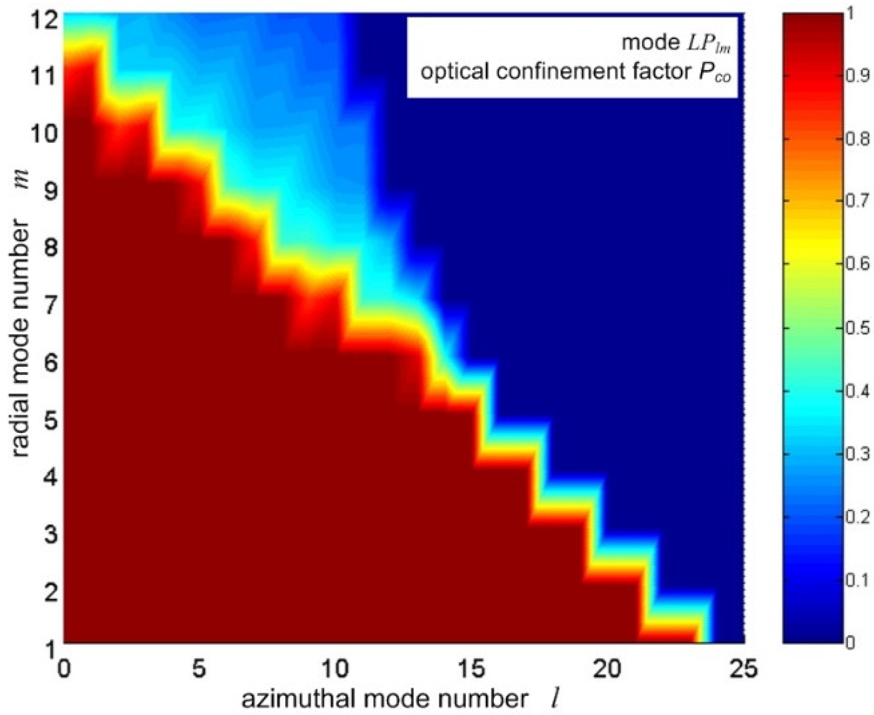
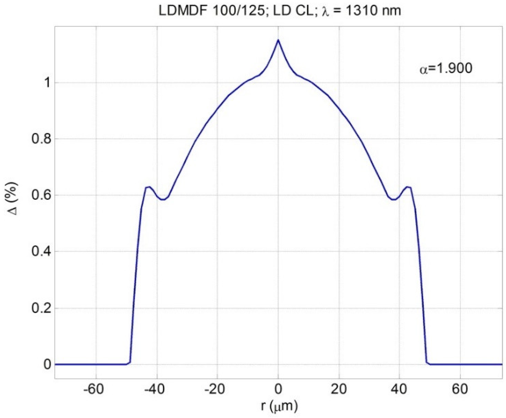
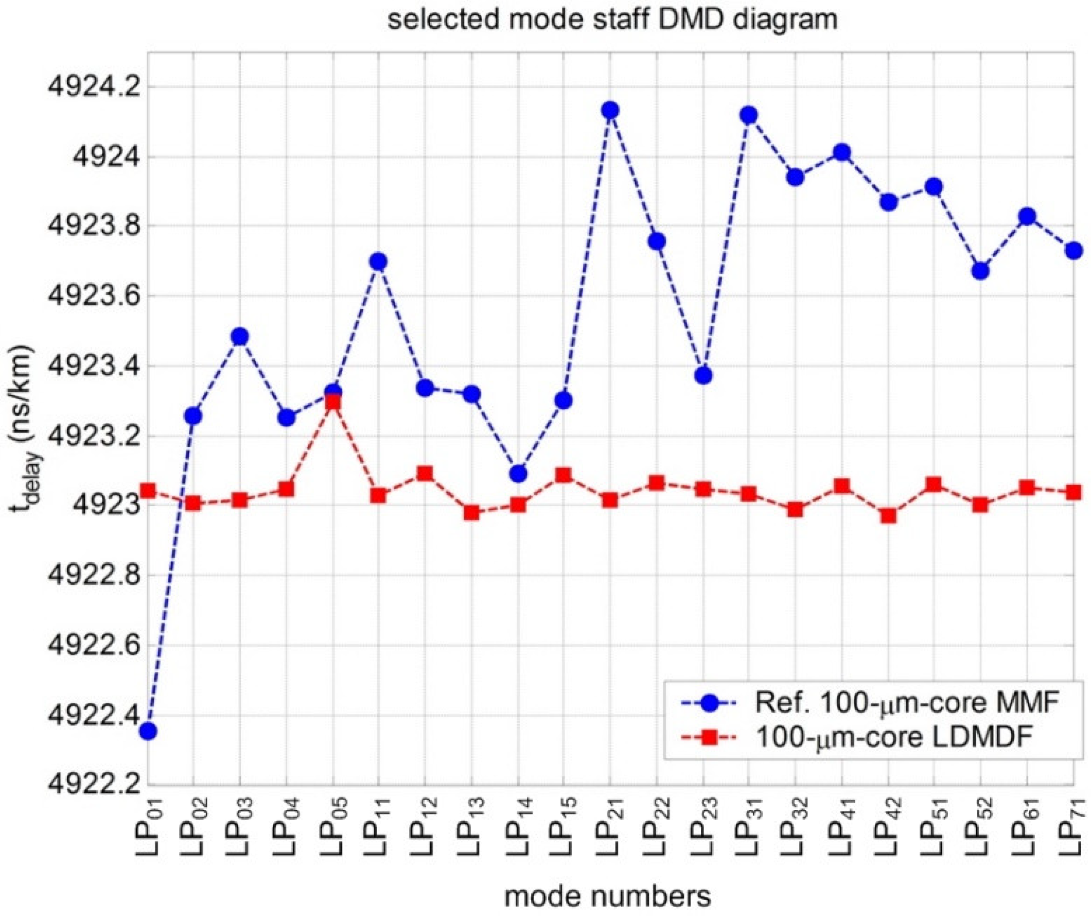
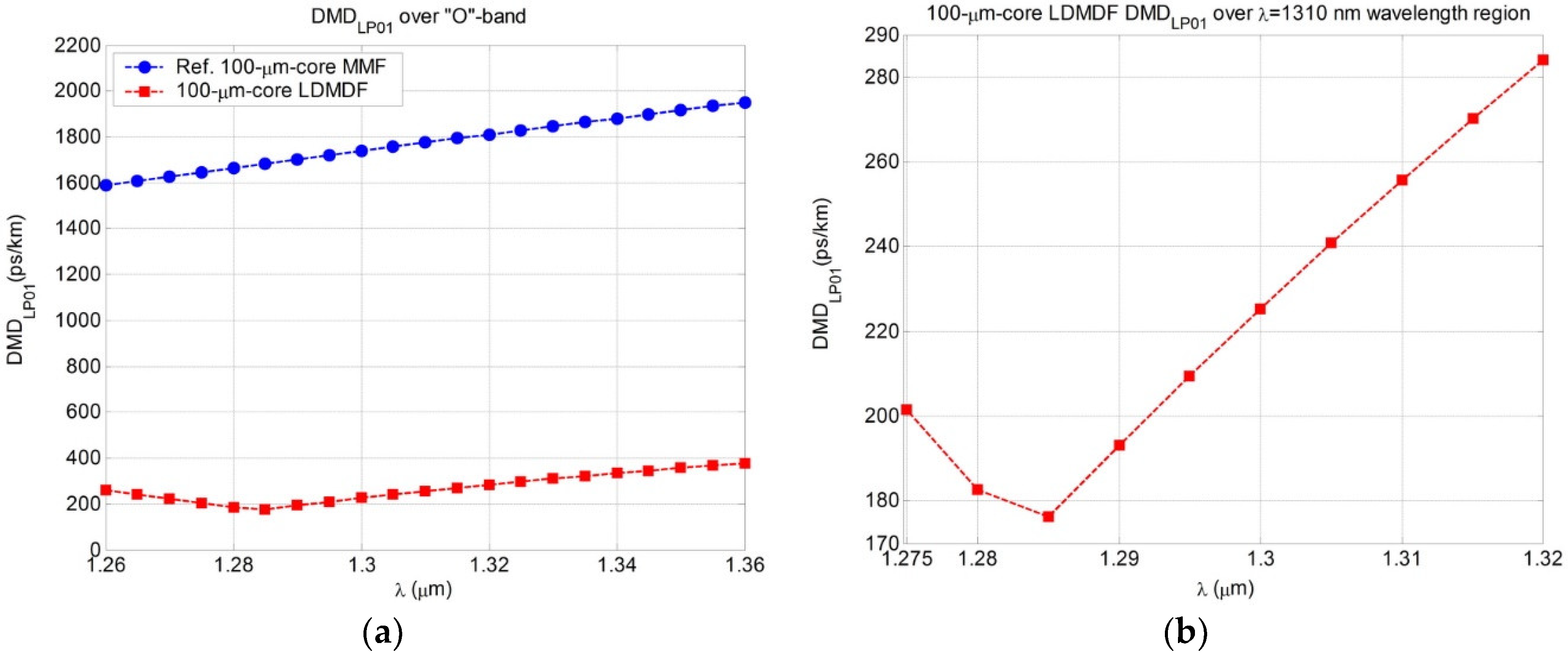
3.1. Low Differential Mode Delay Fiber with a Large 100 µm Core Diameter
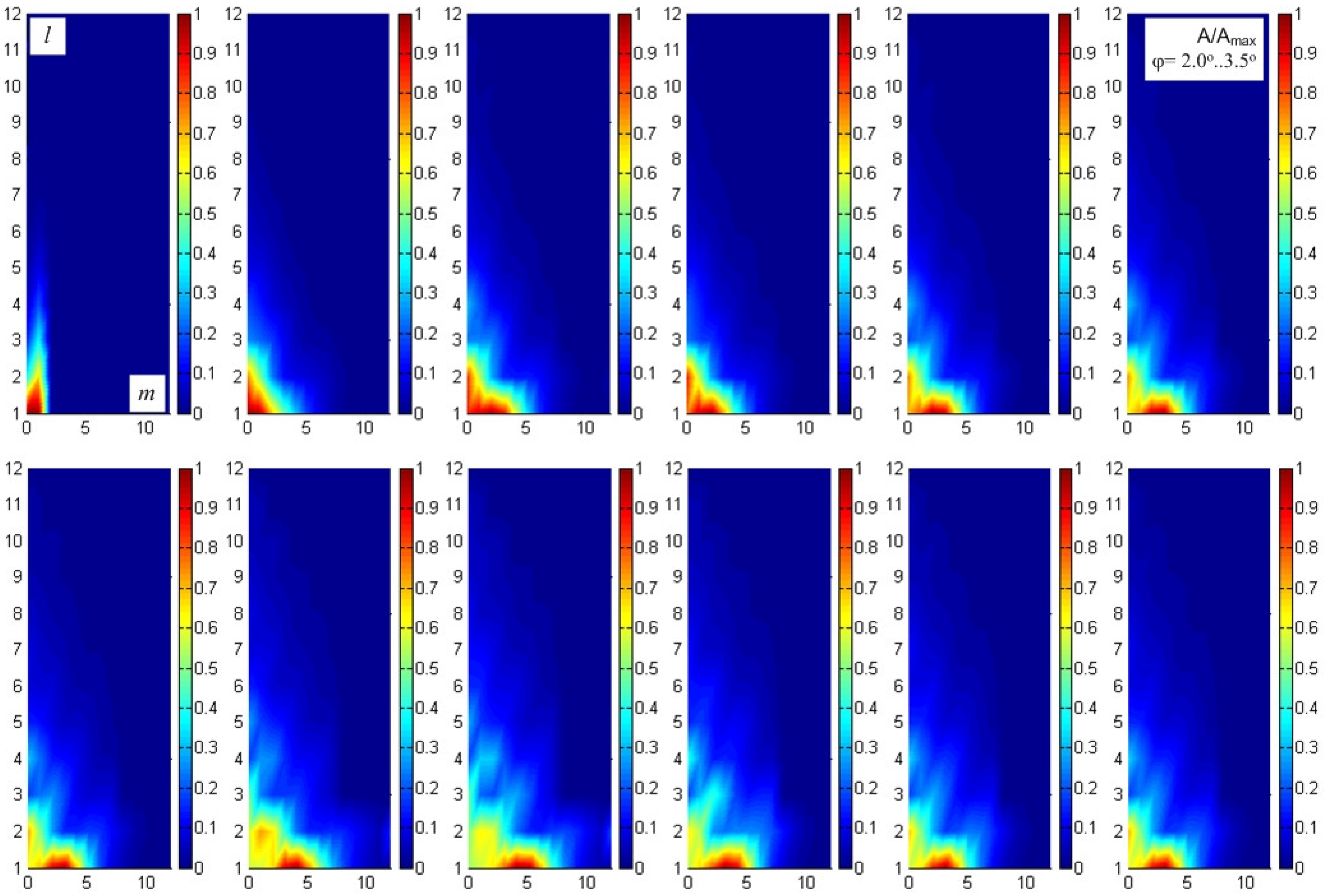
3.2. Simulation of 10GBase-LX Fiber Optic System Optical Pulse Propagation
4. Discussion
5. Conclusions
Author Contributions
Funding
Acknowledgments
Conflicts of Interest
References
- Bottacchi, S. Multi-Gigabit Transmission over Multimode Optical Fibre: Theory and Design Methods for 10GbE Systems; John Wiley & Sons Ltd.: New York, NY, USA, 2008; ISBN 13 978-0-471-89175-8. [Google Scholar]
- Kamino, J. It’s Time for OM5! BICSI Presentation Materials 2017. Available online: https://www.bicsi.org/uploadedfiles/bicsi_conferences/fall/2017/presentations/CONCSES_1C.pdf (accessed on 31 August 2018).
- Mazzarese, D. Optical fiber choice for data centers. Commun. Technol. Equip. 2009, 4, 30–32. [Google Scholar]
- Irujo, T. OM4 Fiber—The Next Generation of Multimode Fiber. BICSI Presentation Materials 2017. Available online: http://www.bicsi.org/pdf/presentations/canada2010/OM4%20Multimode%20Fibers.pdf (accessed on 31 August 2018).
- Freund, R.E.; Bunge, C.-A.; Ledentsov, N.N.; Molin, D.; Caspar, C. High-speed transmission in multimode fibers. IEEE J. Lightware Technol. 2010, 28, 569–586. [Google Scholar] [CrossRef]
- Roberts, C.; Ellis, R. Fiber Selection and Standards Guide for Premises Networks; Corning White Paper: New York, NY, USA, 2013. [Google Scholar]
- Indra, A. Industrial Fiber Optics in Train Transportation Systems; Avago Technologies White Paper: San Jose, CA, USA, 2012. [Google Scholar]
- Liu, S.; Xing, B.; Li, B.; Gu, M. Ship information system: Overview and research trends. Int. J. Naval Arch. Ocean Eng. 2014, 6, 670–684. [Google Scholar] [CrossRef]
- Olson, E. The case for fiber in commercial aircraft: Solving the bandwidth/distance challenge. Mil. Aerosp. Electron. 2016. Available online: https://www.militaryaerospace.com/na/te-connectivity/the-case-for-fiber-in-commercial-aircraft.html (accessed on 31 August 2018).
- Bourdine, A.V. Few-Mode Regime of Optical Signal Transmission over Multimode Optical Fibers: Applications in Modern Iinfocommunications; PSUTI: Samara, Russia, 2011; ISBN 978-5-904029-22-7. [Google Scholar]
- Buckler, M.J.; Kummer, R.; Mettler, S.C.; Miller, M. Fabrication of Optical Fibers Using Differential Mode-Group Delay Measurement. U.S. Patent 4286979, 1 September 1981. [Google Scholar]
- Stone, F.T.; Ritger, A.J.; Head, E.D. The use of a quantitative differential mode delay technique to improve fiber bandwidth. IEEE J. Lightware Technol. 1983, LT-1, 585–587. [Google Scholar] [CrossRef]
- Abbot, J.S.; Harsbarger, D.E. Laser Optimized Multimode Fiber and Method for Use with Laser and System Employing Same. U.S. Patent 2002/0197038, 12 August 2002. [Google Scholar]
- Bangalore Krishnaswamy, P.; Dutta, S.; Panneerselvam, S.R.; Nageswaran, S.K. Optical Fiber Having Higher Bandwidth and Method for Producing the Same. Patent WO 2007/043060, 19 April 2007. [Google Scholar]
- Golowich, S.E.; Jones, S.L.; Ritger, A.J.; Thornburg, K.S. Apparatus and Method for Improving Bandwidth of Multimode Fibers. U.S. Patent 6574403 B1, 3 June 2003. [Google Scholar]
- Achten, F.J.; Jetten, M.P.M.; Krabshuis, G.-J.; Kuyt, G.; Matthijsse, P.; Van Stralen, M.J.N. New generation of broad wavelength window multimode fibres. In Proceedings: ECOC 2004, 30th European Conference on Optical Communication (ECOC), Stockholm, Sweden, 5–9 September 2004; Kista Photonics Research Center: Stockholm, Sweden, 2004; Volume 4, pp. Th 3.3.3-1–Th 3.3.3-3. [Google Scholar]
- Adams, M.J. An Introduction to Optical Waveguides; John Wiley & Sons Ltd.: New York, NY, USA, 1981; ISBN 13 978-0-4712-7969-3. [Google Scholar]
- Bogolyubov, A.N.; Krasilnikov, A.V.; Minayev, D.V.; Sveshnikov, A.G. Finite difference method for solution of the problem of waveguide system synthesis. Math. Model. 2000, 12, 13–24. [Google Scholar]
- Bogolyubov, A.N.; Butkarev, I.A.; Sveshnikov, I.A. Synthesis of optical fibers. Radiotechnika 2004, 12, 4–12. [Google Scholar]
- Bourdine, A.V. Method for chromatic dispersion estimation of high-order guided modes in graded index single-cladding fibers. Proc. SPIE 2006, 6605, 660509-1–660509-13. [Google Scholar]
- Bourdine, A.V. Modeling and simulation of piecewise regular multimode fiber links operating in a few-mode regime. Adv. Opt. Technol. 2013, 2013, 469389-1–469389-18. [Google Scholar] [CrossRef]
- Snyder, A.W.; Love, J. Optical Waveguide Theory; Chapman & Hall: London, UK, 1983; ISBN 978-1-4613-2813-1. [Google Scholar]
- Gradstein, I.S.; Ryjik, I.M. Tables of Integrals, Series and Products; GIFML: Moscow, Russia, 1963; ISBN 978-1-4832-6564-3. [Google Scholar]
- Abramovitz, M.; Stegun, I.A. Handbook of Mathematical Functions with Formulas, Graphs and Mathematical Tables; Nauka: Moscow, Russia, 1979. [Google Scholar]
- Bourdine, A.V.; Delmukhametov, O.R. Calculation of transmission parameters of the launched higher-order modes based on the combination of a modified Gaussian approximation and a finite element method. Telecommun. Radio Eng. 2013, 72, 111–123. [Google Scholar] [CrossRef]
- Binh, L.N. Design Guidelines for Ultra-Broadmand Dispersion-Flattened Optical Fibers with Segmented-Core Index Profile; Technical Report MECSE-14-2003; Monash University: Clayton, Australia, 2003. [Google Scholar]
- Fleming, J.W. Dispersion in GeO2-SiO2 glasses. App. Opt. 1984, 23, 4486–4493. [Google Scholar]
- Burdin, V.A. Methods for computation of Sellmeier coefficients for dispersion analysis of silica optical fibers. Infocom Technol. 2006, 4, 30–34. [Google Scholar]
- Agrawal, G.P. Nonlinear Fiber Optics, 2nd ed.; Academic Press Inc.: San Diego, CA, USA, 1989; ISBN 13 978-0-1204-5142-5. [Google Scholar]
- Yabre, G. Comprehensive theory of dispersion in graded-index optical fibers. IEEE J. Lightware Technol. 2000, 18, 166–177. [Google Scholar] [CrossRef]
- Yabre, G. Influence of core diameter on the 3-dB bandwidth of graded-index optical fibers. IEEE J. Lightware Technol. 2000, 18, 668–676. [Google Scholar] [CrossRef]
- Srapionov, V.A. Mode coupling at the splices of optical fibers with mismatched parameters. Elektrosvyaz 1985, 10, 10–12. [Google Scholar]
- Bourdine, A.V. Mode coupling at the splice of diverse optical fibers. Proc. SPIE 2012, 8787, 878706-1–878706-12. [Google Scholar]
- Bourdine, A.V.; Praporshchikov, D.E.; Yablochkin, K.A. Investigation of defects of refractive index profile of silica graded-index multimode fibers. Proc. SPIE 2011, 7992, 799206-1–799206-6. [Google Scholar]
- Demidov, V.V.; Ter-Nersesyants, E.V.; Bourdine, A.V.; Burdin, V.A.; Minaeva, A.Y.; Matrosova, A.S.; Khokhlov, A.V.; Komarov, A.V.; Ustinov, S.V.; Golyeva, E.V.; et al. Methods and technique of manufacturing silica graded-index fibers with a large central defect of the refractive index profile for fiber-optic sensors based on few-mode effects. Proc. SPIE 2017, 10342, 103420X-1. [Google Scholar]
- Raddatz, L.; White, I.H.; Cunningham, D.G.; Nowell, M.C. An experimental and theoretical study of the offset launch technique for the enhancement of the bandwidth of multimode fiber links. IEEE J. Lightware Technol. 1998, 16, 324–331. [Google Scholar] [CrossRef]
- Gowar, J. Optical Communication Systems; Pfentice/Hall International: London, UK, 1984; ISBN 13 638156-1. [Google Scholar]
- Cunningham, D.; Nowell, M.; Hanson, D. Proposed Worst Case Link Model for Optical Physical Media Dependent Specification Development. IEEE 802.3z Task Force Presentation Materials, January 1997. Available online: http://www.ieee802.org/3/z/public/presentations/jan1997/dc_model.pdf (accessed on 31 August 2018).
- Cunningham, D.; Nowell, M.; Hanson, D.; Kazovsky, L. The IEEE 802.3z Worst Case Link Model for Optical Physical Media Dependent Specification. IEEE 802.3z Task Force Presentation Materials, March 1997. Available online: http://www.ieee802.org/3/z/public/presentations/mar1997/DCwpaper.pdf (accessed on 31 August 2018).
- Clarifying Optical Parameters, Power Budgets, and Fiber Plant Requirements for 10GBase-E and 10GBase-L. Cisco Systems White Papers 2005. Available online: https://www.cisco.com/c/en/us/products/collateral/interfaces-modules/10-gigabit-modules/prod_white_paper0900aecd8033fa80.pdf (accessed on 31 August 2018).


© 2018 by the authors. Licensee MDPI, Basel, Switzerland. This article is an open access article distributed under the terms and conditions of the Creative Commons Attribution (CC BY) license (http://creativecommons.org/licenses/by/4.0/).
Share and Cite
Bourdine, A.V.; Burdin, V.A.; Janyani, V.; Ghunawat, A.K.; Singh, G.; Zhukov, A.E. Design of Silica Multimode Optical Fibers with Extremely Enlarged Core Diameter for Laser-Based Multi-Gigabit Short-Range Optical Networks. Photonics 2018, 5, 37. https://doi.org/10.3390/photonics5040037
Bourdine AV, Burdin VA, Janyani V, Ghunawat AK, Singh G, Zhukov AE. Design of Silica Multimode Optical Fibers with Extremely Enlarged Core Diameter for Laser-Based Multi-Gigabit Short-Range Optical Networks. Photonics. 2018; 5(4):37. https://doi.org/10.3390/photonics5040037
Chicago/Turabian StyleBourdine, Anton V., Vladimir A. Burdin, Vijay Janyani, Ashish Kumar Ghunawat, Ghanshyam Singh, and Alexander E. Zhukov. 2018. "Design of Silica Multimode Optical Fibers with Extremely Enlarged Core Diameter for Laser-Based Multi-Gigabit Short-Range Optical Networks" Photonics 5, no. 4: 37. https://doi.org/10.3390/photonics5040037
APA StyleBourdine, A. V., Burdin, V. A., Janyani, V., Ghunawat, A. K., Singh, G., & Zhukov, A. E. (2018). Design of Silica Multimode Optical Fibers with Extremely Enlarged Core Diameter for Laser-Based Multi-Gigabit Short-Range Optical Networks. Photonics, 5(4), 37. https://doi.org/10.3390/photonics5040037