Article

High Harmonics with Controllable Polarization by a Burst of Linearly-Polarized Driver Pulses

1
Solid State Institute and Physics Department, Technion—Israel Institute of Technology, Haifa 32000, Israel
2
Department of Physics and Optical Engineering, Ort Braude College, Karmiel 21982, Israel
*
Author to whom correspondence should be addressed.
Photonics 2017, 4(2), 31; https://doi.org/10.3390/photonics4020031
Submission received: 3 March 2017 / Revised: 8 April 2017 / Accepted: 13 April 2017 / Published: 17 April 2017
(This article belongs to the Special Issue Extreme UV Lasers: Technologies and Applications)

Abstract

:
We theoretically explore a scheme for generation of bright circularly and elliptically polarized high-order harmonics by bursts of linearly polarized pulses with a rotating polarization axis. Circularly polarized harmonics are formed if the bursts are comprised of N pulses that uphold an N-fold rotational symmetry, for N > 2. Rotating the polarization axes of the comprising pulses can generate elliptical harmonics with a collectively tunable ellipticity, from circular through elliptic to linear. The method preserves the single-cycle, single-atom and macroscopic physics of ‘standard’ linearly polarized high harmonic generation, with a high yield and cutoff energy. We investigate the method from a time-domain perspective, as well as a photonic perspective, and formulate the energy and spin-angular momentum conservation laws for this scheme. We find that the case of N = 4 is optimal for this method, resulting with the highest conversion efficiency of elliptical photons. The new features of this source offer new applications to helical ultrafast spectroscopy and ellipsometry.

1. Introduction

High harmonic generation (HHG) is a nonlinear process in which intense laser radiation interacts with matter to emit extreme UV and X-ray coherent light [1,2]. The process is well described by the semi-classical three-step model, where the strong electric field ionizes electrons, which then accelerate, and proceed to re-collide with the ions. Upon re-collision, high energy photons are emitted [3,4]. The spectrum of this process is largely determined by the driving laser field. For example, dynamical symmetries (DSs) present in the laser field can impose selection rules on the harmonic emission [5,6]. Additionally, if the driver is linearly-polarized, then so are the emitted harmonics, while an elliptically polarized driver leads to elliptical harmonics [7,8,9]. Unfortunately, an elliptical driver drastically reduces the probability for re-collisions, lowering the yield [10,11]. For many years this effect limited the generation of bright highly helical high harmonics.
Nonetheless, theoretical [10,11,12,13,14,15,16,17,18,19,20,21,22] and experimental [23,24,25,26,27,28,29,30,31,32,33,34,35] advancements have been accomplished over the years. In particular, circular harmonics were produced using a bi-circular driving laser field [26,27,30,31,34,35]. In the bi-circular scheme, two counter-rotating circular pulses of different frequencies drive HHG. The coherent superposition of two such pulses creates unique laser fields with rotational DSs, in which the electron has a high probability to recombine, and due to symmetry emit circular harmonics [6]. Additionally, high harmonics with a relatively high ellipticity (up to 0.8 at photon energy 25 eV) were generated with an elliptically polarized pump driving a gas of SF6 molecules [28], and with bi-chromatic co-propagating orthogonally polarized pumps driving atomic Ne gas [29]. Circular harmonics were also produced by mixing non-collinear circularly polarized counter-rotating pumps [30].
The above methods have various advantages, but are still limited in several aspects. Importantly, none of them allow to fully control the ellipticity of high harmonics (from circular through elliptical to linear) in a manner that is uncoupled to the generation efficiency. Moreover, the ellipticity is tunable for only a given harmonic at a time, and not for an entire spectral region. Lastly, compared to ‘standard’ linearly polarized HHG schemes driven by linearly polarized pulses, the conversion efficiency and cutoff energy of circular HHG are smaller. Overcoming these limitations could have applications in coherent control, and ultrafast spectroscopy of chiral processes. Also, a tunable polarization will allow HHG based null-ellipsometry, generalized-ellipsometry, and imaging ellipsometry [36,37].
Recently, we theoretically proposed and demonstrated numerically a new scheme for generation of bright circularly and elliptically polarized high harmonics [38]. In this scheme, the HHG process is driven by a burst of linearly polarized quasi-monochromatic pulses with rotating polarization axes. When the angle between consecutive pulses is 120°, the driving laser exhibits a 3-fold DS, similarly to the ω-2ω bi-circular scheme, hence the generated high harmonics are circularly polarized and its power spectrum consists of harmonic pairs with opposite helicity. However, while the frequency difference between each pair is ω in the ω-2ω bi-circular scheme, it is much smaller in the new scheme (it corresponds to the duration in which the driver field exhibits a 3-fold DS). Thus, this scheme requires a high-resolution spectrometer or narrow chiral resonances. Tuning the relative orientation of the pulses (away from 120°) allows controlling the ellipticity of the entire spectrum collectively, with almost no compromise on the yield, and with minimal coupling to the spectrum. The only small coupling is manifested by the appearance of new ‘previously forbidden’ harmonic peaks, which radiate with a relatively low intensity. Importantly, this scheme allows to fully control the polarization of the harmonics while largely preserving the single-cycle, single-atom and macroscopic physics of ‘standard’ HHG, where the driver and the emitted harmonics are linearly polarized. A weakness of the method is that it requires fine control over the driving pulse-burst (see Figure 5 in Reference [38]).
Here we extend our investigations of the previously proposed scheme for generation of bright high harmonics with fully controllable polarization driven by bursts of three linearly polarized pulses. First, we generalize the scheme to N pulses. The harmonics are polarized circularly when the polarization axis of the pulses upholds an N-fold rotational DS. Varying the relative polarization axes of the pulses (away from an N-fold symmetry) allows fine-tuning of the high harmonics ellipticity. Second, we show that this process is analytically equivalent to diffraction from N-slits. Third, we investigate the process and derive the selection rules using energy and spin angular momentum conservation laws for the participating photons. Lastly, we show that in the case of N = 4 the method results in a maximal conversion efficiency, and a noise free broad-wavelength elliptical spectrum for any target ellipticity.
The paper is ordered as follows: Section 2 presents the general scheme. Section 3 provides an analytical time-domain model, and also discusses the frequency-domain perspective and conservation laws. In Section 4 we numerically verify the scheme, and Section 5 summarizes our results.

2. High Harmonic Generation Scheme

HHG is a collision-based phenomenon. Unfortunately, a single electronic re-collision is not likely to yield a highly helical photon. This is a consequence of the electron having a well-defined vector momentum upon impact, which determines the polarization axis of the emitted photon. Accordingly, it is challenging to generate bright highly elliptical harmonics from a single recollision event. One method for overcoming this difficulty is obtaining helical harmonics through interfering several recollision events. For instance, in the bi-circular scheme described above, three distinct events from each sub-cycle interfere to produce circular harmonics. We describe here a scheme that also relies on an interference mechanism, but in this case the events are temporally separated from one another on much longer time-scales. This is accomplished by driving the process with a burst of pulses.
The pulse-burst is comprised of linearly-polarized pulses with a varying polarization axis. When the pulses within the burst are temporally distinct, each pulse drives “regular” one-dimensional HHG, producing linearly-polarized harmonics. Circularly polarized radiation can then be generated by correctly choosing the different parameters in the pulse-burst. The desired polarization direction (orientation) of each pulse can be found from symmetry considerations. For a burst consisting of N consecutive collinearly propagating, isochronal, linearly-polarized light pulses, circular polarization is obtained only if the orientations of each pulse follows the consecutive roots of unity. That is, the orientation angle of each pulse above the x-axis, θ, upholds: e i θ = 1 N , thus, θ = k × 2π/N, for k = 0, 1, …, N − 1. Clearly, circular polarization can only be attained for N > 2, since otherwise all the pulses are polarized along the same axis. For instance, for N = 3 we require three pulses oriented at 120° from one another, as we previously showed in Reference [38]. In the time-domain, this criterion means the pulse-burst complies to a rotational DS of N’th order. Thus, a burst consisting of N linearly-polarized pulses which leads to circular polarization upholds:
E b u r s t ( t + T N N ) = R ^ ( 2 π N ) E b u r s t ( t )
where E b u r s t ( t ) is the driver laser field, TN is the cycle time of the DS, and R ^ ( 2 π / N ) is a two dimensional (2D) rotation operator by an angle of 2π/N. This DS leads to circular harmonics [6], and is similar to the DS present in the bi-circular fields, but for a longer period. A general pulse-burst that upholds Equation (1) can be written as:
E b u r s t ( N ) ( t ) = m = ( M 1 ) / 2 ( M 1 ) / 2 E U C ( N ) ( t m T N )
where the unit cell (UC) train is defined as:
E U C ( N ) ( t ) = k = 0 N 1 E l i n ( t k T N N ; θ = k 2 π N ) ,
and
E l i n ( t ; θ ) = E 0 A ( t ) sin ( ω 0 t ) [ cos ( θ ) x ^ + sin ( θ ) y ^ ]
T N = N ( N p + 1 ) T + N τ
where E l i n ( t , θ ) is the electric field of a single pulse, polarized at an angle θ above the x-axis, with a duration of (Np + 1) optical cycles. E0 is the field amplitude, ω0 is the optical frequency, and A(t) is a real envelope function. The burst in total contains M repetitions of TN long cycles, and each of the individual linearly-polarized pulses is separated by a time τ from the next, such that the overall period of the DS is given in Equation (5), where T is the cycle of the optical frequency T = 2π/ω0. Figure 1 shows examples of such a pulse-burst for M = 1, and N = 4 and 5.
Beyond circular harmonics, this approach can be used to manipulate the ellipticity of the harmonic spectrum. Tweaking the relative angles between pulses varies the polarization of the harmonics across the spectrum. This process breaks the circular DS in Equation (1), but in a controlled manner, because the physical nature of the scattering events remains unchanged. In Reference [38] we showed this is the case for N = 3, but generally a similar approach can be used for an arbitrary amount of pulses, N.

3. Analytical Model

3.1. Circular Harmonics

We begin our analysis by formulating an analytical model for the harmonic dipole response induced by a pulse-burst consisting of N linearly-polarized pulses of the form of Equation (2). Since the pulses are temporally distinct, we model each recollision as a simple delta-function like response occurring at the peak of every half-optical cycle of the driver. For simplicity, we assume the pulse-bursts are temporally symmetric, such that Np is an even integer, and M is an odd integer. The vectorial components of the harmonic emission then take the form:
a x ( N ) ( t ) = m = ( M 1 ) / 2 ( M 1 ) / 2 k = 0 N 1 cos ( 2 π N k ) f ( t T N N k m T N )
a y ( N ) ( t ) = m = ( M 1 ) / 2 ( M 1 ) / 2 k = 0 N 1 sin ( 2 π N k ) f ( t T N N k m T N ) ,
where
f ( t ) n = N p / 2 N p / 2 δ ( t n T ) n = N p / 2 N p / 2 δ ( t n T T / 2 )
is the response to a single linearly-polarized pulse with (Np + 1) fundamental cycles, δ(t) is the Dirac delta function, a ( t ) = a x ( t ) x ^ + a y ( t ) y ^ is the vector polarization, and other parameters are as detailed previously. The assumed delta function form can be relaxed to some other broadened function, like a Gaussian, without quantitatively changing the analysis. In particular, broadening adds a spectral envelope function, which does not change the polarization.
Next, we calculate the harmonic spectrum defined by a Fourier transform of the dipole response, where the spectrum is projected onto left and right circular components through:
a ˜ + / ( Ω ) = [ a x ( t ) ± i a y ( t ) ] = a ˜ x ( Ω ) ± i a ˜ y ( Ω )
where represents a Fourier transform. The spectral power of the left and right helical components is retrieved as the absolute power of Equation (9):
I ˜ + / ( Ω ) = | a ˜ + / ( Ω ) | 2
Calculating the Fourier transforms of Equations (6)–(8) we find:
I ˜ + / ( N ) ( Ω ) = 2 π sin 2 ( Ω T 4 ) ( 1 + 2 n = 1 N p / 2 cos ( n Ω T ) ) 2 ( 1 + 2 m = 1 ( M 1 ) / 2 cos ( m Ω T N ) ) 2 sin 2 ( Ω T N 2 ) sin 2 ( Ω T N 2 N ± π N )
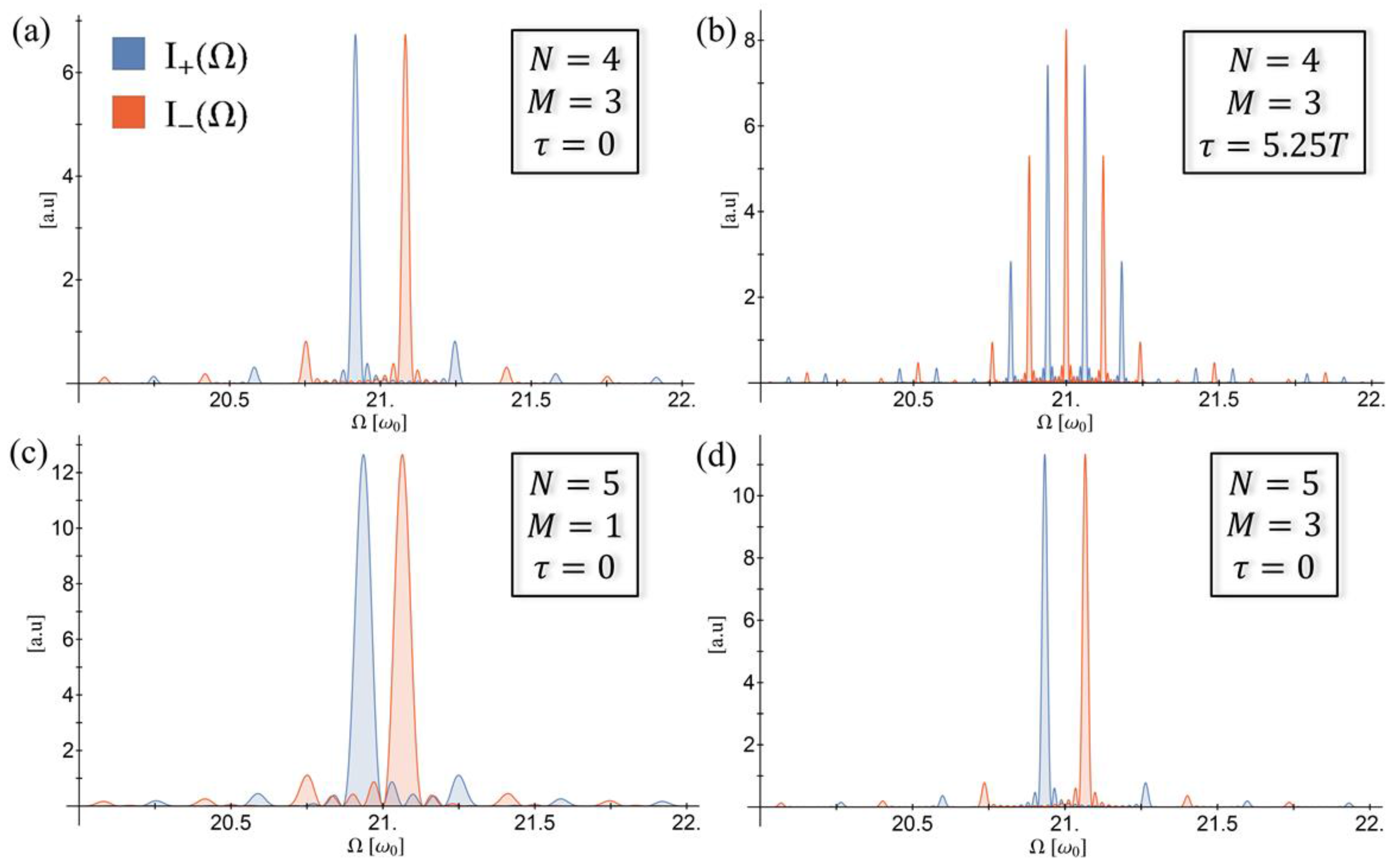
where the sum of a geometric series was used. The spectral power in Equation (11) can be seen in Figure 2 for several values of parameters, and is comprised of four dominant terms. The two leftmost terms provide an envelope function which intensifies near odd integers of the optical frequency, and goes to zero at even integers. This is understood as a consequence of “standard” linearly-polarized HHG selection rules, since each individual pulse complies to a 2-fold DS of period T. The third term determines the spectral width of any allowed emission, which is inversely proportional to the square root of the length of the pulse-burst, 1 / M , as seen in comparing Figure 2c to Figure 2d. The last term dictates the new selection rules for an N’th order burst, which are found by straightforward functional analysis:
Ω ( N ) , q / + = 2 π T N ( N q ± 1 ) , q
These are also the expected selection rules due to the rotational DS the pulse-burst upholds, as has been previously derived [6,39]. The allowed harmonics are therefore found at the frequencies in Equation (12), and are exactly circular at the peak, with alternating helicities. The only exceptions are for the trivial N = 1 and N = 2 cases, which result in linearly-polarized light. This emission forms an uneven and dense frequency comb, where for increasing TN the comb’s density is increased (the limiting factor of spectral resolution is the free spectral range: 2π/TN). By changing the delay between the linearly-polarized pulses, τ, one can shift the harmonic frequencies such that they are not necessarily rational fractions of the original optical frequency (according to Equations (5) and (12)). This gives exact continuous control of the emitted frequencies, and can be seen for example in Figure 2a compared to Figure 2b.
Interestingly, HHG with this scheme is mathematically equivalent to a diffraction pattern in the far field from N slits (as seen in the last term in Equation (11), which is identical to an N-slit diffraction pattern). The amount of pulses in the burst (N) act as the number of slits (or point sources for diffraction). The “order” of diffraction corresponds to the harmonic order of the emitted frequency, where the repetition time, TN, acts the role of the distance between slits. The duration of each pulse (Np) and the fundamental optical period (T) together give rise to a spectral envelope function (as the first two terms in Equation (11) suggest), and thus correspond to the width of each slit.

3.2. Polarization Control

The above scheme can be altered in order to produce harmonics with a desired degree of ellipticity. This is achieved by changing the relative orientations of the pulses within the burst. In previous work [38] we directly showed this is the case for N = 3, where it was shown that a single free parameter could be used as a knob for collectively controlling the ellipticity of harmonics in the spectrum, with minimal energy loss. We now show that this is also the case for any order N.
The ellipticity of the emitted harmonics is determined by the relative amplitude and phase of the x and y components of the polarization. Therefore, rotating the orientations of the pulses allows controlling the projections of the harmonics on the polarization ellipse. For each order N, many possible schemes to manipulate the emitted harmonics’ ellipticity in this manner exist. In all these schemes, the degree of symmetry breaking can be described by a single “progression parameter”, “e”, which is continuously varied from 1 to 0. We set that for e = 1, all schemes degenerate to the symmetric configuration described above, yielding circular harmonics. For e = 0, all pulses are oriented along the x-axis, and thus all harmonics are linearly-polarized. In between we get the full range of elliptical polarization control.
For the sake of simplicity, we focus on ellipticity control schemes that are symmetric with respect to the x-axis. For instance, one such choice is to slowly orient all pulses towards the positive or negative directions along the x-axis according to their initial orientation, such that they follow the shortest path. This is seen for example in the insets of Figure 3 for N = 3–5. Mathematically, this is described by rotating the dipole response of the k’th pulse in the burst from Equations (6)–(8) by an angle shift θ k ( e ) , such that the angle of each pulse is θ = 2 π N k + θ k ( e ) above the x-axis:
a x ( N ) ( t ) = m = ( M 1 ) / 2 ( M 1 ) / 2 k = 0 N 1 cos ( 2 π N k + θ k ( e ) ) f ( t T N N k m T N ) a y ( N ) ( t ) = m = ( M 1 ) / 2 ( M 1 ) / 2 k = 0 N 1 sin ( 2 π N k + θ k ( e ) ) f ( t T N N k m T N ) ,
where
θ k ( e ) { ( 1 e ) × 2 π ( k N ) ; 0 2 k N < 1 2 ( 1 e ) × 2 π ( 1 2 ( k N ) ) ; 1 2 2 k N < 1 ( 1 e ) × 2 π ( k N 1 2 ) ; 1 2 k N < 3 2 ( 1 e ) × 2 π ( 1 k N ) ; 3 2 2 k N < 2 0 ; o t h e r w i s e }
With this approach, the ellipticity of the harmonics from Equation (12) can be calculated analytically:
ε ( N ) ( Ω ( N ) , q ± ) = | k = 0 N 1 sin ( 2 π N k + θ k ( e ) ) exp ( i 2 π k N ) k = 0 N 1 cos ( 2 π N k + θ k ( e ) ) exp ( i 2 π k N ) |
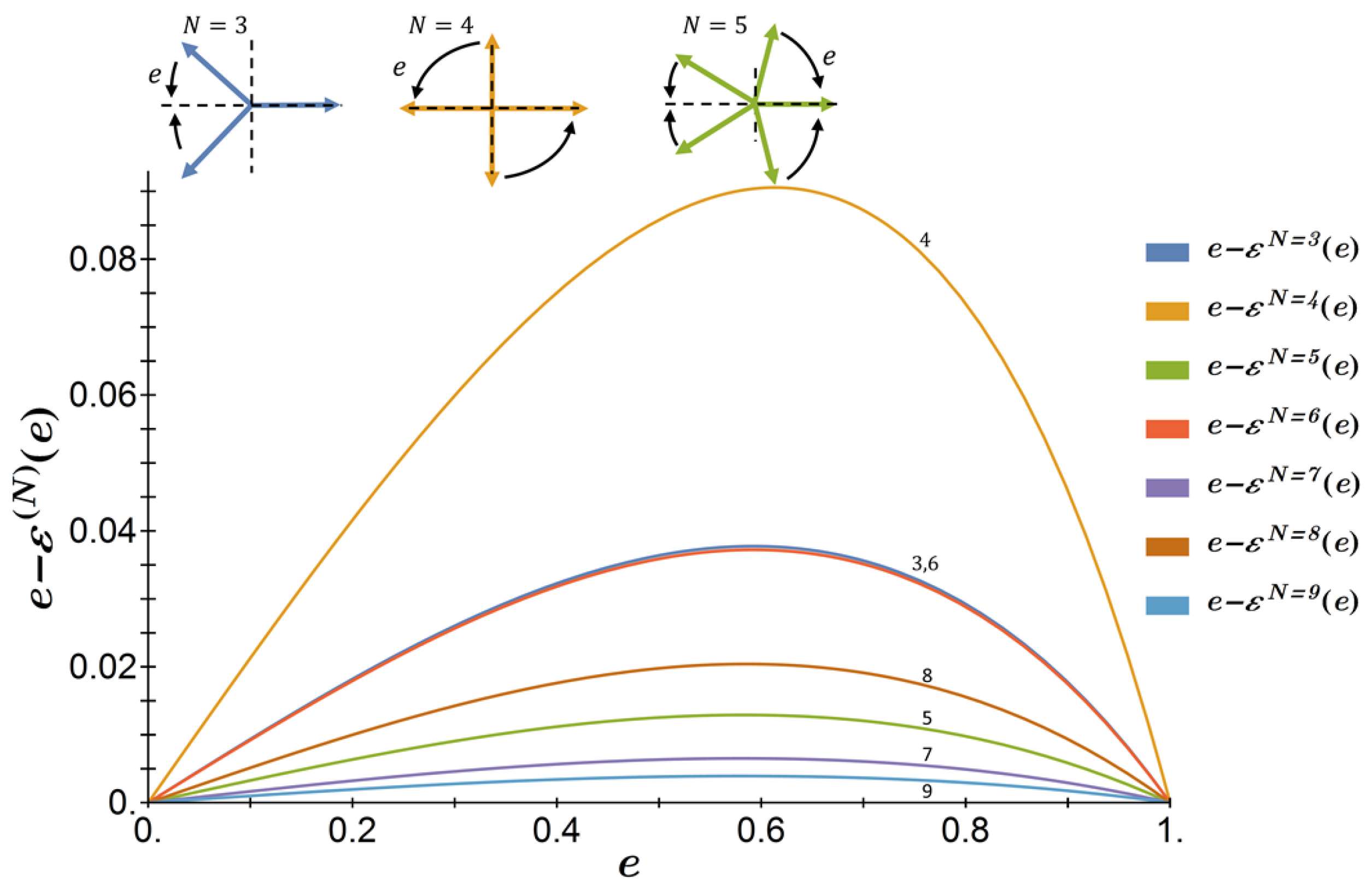
where the calculation applies for the allowed frequencies given in Equation (12). Equation (15) shows that the ellipticity does not depend on the harmonic order (the index q or ± sign do not appear in Equation (15)), and is thus identical for all harmonics in the spectrum of the form of Equation (12). For the choice θ k ( e ) according to Equation (14), the ellipticity is almost linear in “e”, and becomes closer to linear for higher orders of N. For example, for N = 4 Equation (15) reduces to:
ε ( 4 ) ( Ω q ± ) = tan ( π 4 e )
Figure 3 shows the deviation between the ellipticity as a function of “e” and the linear line ε ( N ) = e for the cases N = 3–9. All cases closely follow the linear line (up to variations of 0.1 in ellipticity), while higher values of N approach the linear limit as N (even and odd values of N separately). The approximately linear control over an extremely nonlinear process such as HHG, is due to the linear nature of interference which determines the ellipticity in our scheme, even though the generation process is highly nonlinear. Moreover, the intensities of the high harmonics in this interference-based approach are largely insensitive to the ellipticity tuning. Any small variation in the intensities of the harmonics is due to the appearance and growth of harmonics that become allowed when the rotational DS is broken. Thus, minimizing the number of these new harmonics increases the intensity robustness to ellipticity tuning. For example, for even values of N, there is always a θ k ( e ) scheme which maintains a 2-fold rotational DS, allowing only odd-only harmonics in the spectrum [5]. A particularly special case is N = 4, where all odd harmonics are allowed. During ellipticity tuning no new peaks appear in the spectrum, resulting in maximal conversion efficiency, and a “clean” spectrum of elliptical harmonics for any desired ellipticity.

3.3. Photonic Conservation Laws

The selection rules in the above time-domain analysis are derived from the DS of the driver. Additionally, we wish to accompany the above formulation with a photonic derivation of energy and spin-angular momentum (SAM) conservation laws, which result in the same selection rules, but different intuition. Especially, one might be concerned that nonlinear mixing of linearly polarized photons yields circularly polarized high harmonic photons, since this seems to defy conservation of SAM.
To begin this analysis, we first calculate the spectral intensity of our driver pulse-burst, where for simplicity we assume that the individual pulses are square and not trapezoid. The spectral power is calculated as the absolute value of the Fourier transform of the driver (Equation (2)), projected onto left and right helical components:
P ˜ ± ( N ) ( Ω ) = | [ E x ( t ) ± i E y ( t ) ] | 2 = = | E 0 | 2 sin 2 ( ( Ω ω 0 ) 2 ( T N N τ ) ) ( Ω ω 0 ) 2 ( 1 + 2 m = 1 ( M 1 ) / 2 cos ( m Ω T N ) ) 2 sin 2 ( Ω T N 2 ) sin 2 ( Ω T N 2 N ± π N )
where P ˜ ± ( N ) is the left/right circularly projected spectral power of the driver field with N pulses, and other parameters are as previously defined. The leftmost term in Equation (17) is a sinc envelope around the fundamental frequency due to the finite duration of each linear pulse within the burst. The next terms are familiar from Equation (11) for the HHG spectrum, and play a similar role. This is not surprising, since the driver itself complies to the N-fold DS, thus the selection rules for the emitted light should also apply to the driver. Therefore, the spectrum of the driver field is comprised of left and right circularly polarized photons at identical energies to those in Equation (12). This can be seen in Figure 4 for exemplary cases. It should be noted that the driver primarily contains two types of circular photons appearing near the fundamental frequency ω0. Other types of photons in the driver are a result of multiple pulses within the burst, but are scarce due to the sinc envelope. We will return to this point later.
Next, due to conservation of SAM:
σ ( p ) = ± 1 = N 1 N 2
where σ ( p ) is the spin of the p’th emitted harmonic, N1 and N2 are the number of right and left circularly polarized photons annihilated in the process, respectively, and the index “N” was omitted since the following analysis is performed for the general case of bursts consisting of N pulses. This is under the assumption that the orbital-angular momentum of the driven atom/molecule is unchanged in the process, otherwise it should be added to the analysis as well [39]. Equation (18) means there must be one more, or one less, right polarized photon than left polarized photons annihilated. Also, this means N1 + N2 is an odd integer, which conserves parity (thus in this case SAM conservation is a much stronger constraint compared to parity conservation).
To explicitly write out the energy conservation law, in annihilating N1 + N2 driver photons into a single high-harmonic photon, we must know the energies of each of the annihilated photons. However, since the driver is only quasi-monochromatic, it has an infinite amount of photons with different energies, making this analysis complicated. To overcome this complexity, we first assume N1 > N2, meaning σ ( p ) = 1 . Furthermore, due to the driver’s spectrum and its comprising photons, each annihilated photon can be characterized by a single integer number, q. Then the energy of the p’th emitted harmonic is:
Ω ( p ) + = 2 π T N [ k = 1 N 1 ( N q ( + ) k 1 ) ] + 2 π T N [ k = 1 N 2 ( N q ( ) k + 1 ) ]
where q k ( + / ) are integers determining the energy of the kth annihilated photon with +/− helicity, using Equation (12). Plugging in the SAM conservation constraint, we get N1 = N2 + 1, which reads:
Ω ( p ) + = 2 π T N [ k = 1 N 2 + 1 ( N q ( + ) k 1 ) ] + 2 π T N [ k = 1 N 2 ( N q ( ) k + 1 ) ]
Now we single-out the last (+) polarized annihilated photon (last term in the left sum), which allows combining the two sums:
Ω ( p ) + = 2 π T N [ N { q ( + ) N 2 + 1 + k = 1 N 2 ( q ( + ) k + q ( ) k ) } 1 ]
Finally, we note that the term in the curly brackets in Equation (21) is a sum of integers, therefore it is an integer number itself, which we denote by p :
Ω ( p ) + = 2 π T N ( N p 1 )
Without any other assumption, we directly obtain the selection rules as derived in the previous section: a right circularly polarized photon can only be emitted at energies of 2 π T N ( N p 1 ) , where p is any integer. Repeating this derivation for N2 > N1 results in a similar conclusion: a left circularly polarized photon can only be emitted at energies of 2 π T N ( N p + 1 ) .
Overall, the selection rules resulting from conservation laws are identical to those derived analytically in the previous section. Harmonics are circularly polarized at the frequencies given by Equation (12), with the exception of N = 1 and N = 2, which result in linearly-polarized harmonics since then the pulse-burst is polarized along a single dimension.
The envelope function that prefers odd integer harmonics of the fundamental (the first two terms in Equation (11)) can also be explained intuitively in the photonic picture: due to the sinc envelope around the fundamental frequency in the driver’s spectrum (first term in Equation (17)), processes involving photons with energies close to ω0 are greatly preferred, seeing as there are simply many more of these types of photons. Additionally, since only an odd number of photons is annihilated due to Equation (18), multiple annihilation of these photons leads to odd integer multiples of ω0 at a high probability. In contrast, in order to get emission near even integer multiples of ω0, two photons with energies close to ω0, plus an additional low energy photon need to be annihilated, which has a low probability to occur. Gaining intuition through the conservation-law arguments presented above is somewhat limited, since the number of possible channels contributing to the emission of a given harmonic grows combinatorically with the harmonic order, and as such is large. For instance, combinatorial arithmetics shows that there are a total of 21 different channels through which a photon of energy 2 π T N ( N p 1 ) with an index p = 15 can be created. Nevertheless, since the abundance of driver photons is limited to only few type of photons, not all harmonic channels contribute, and the general qualitative behavior of the HHG emission can still be grasped using the conservation-law picture.
Lastly, we note that this approach is not very effective for the general elliptical case. In this case the requirement for conservation of parity and SAM is not strong enough to derive information on the possible harmonic channels. The driver now has both (+) and (−) spin photons in every allowed energy with a known ratio determined by the relative angle between pulses. However, this ratio is not kept in the individual channels of emitted photons due to the extreme non-linear nature of the HHG process. This is somewhat analogous to the loss of rotational symmetry in the time-domain.

4. Quantum Simulations

4.1. Numerical Model

Our analytical considerations are supported by numerical simulations. We numerically solved the 2D time dependent Schrödinger equation (TDSE) in the length gauge, within the single active electron (SAE), and the dipole approximations. The TDSE in atomic units is:
i t | ψ ( t ) = ( 1 2 2 + V a t o m ( r ) + r E b u r s t ( t ) ) | ψ ( t )
where | ψ ( t ) is the time-dependent wave function of the single electron, and V a t o m ( r ) is the atomic potential well. We used a spherical atomic potential model, where the electron is initially in the 1s ground state orbital, found by complex time propagation. We used a softened Coulomb interaction, set for the first ionization potential of Ne atom (Ip = 0.793 a.u.). The atomic potential is taken according to Reference [40]:
V a t o m ( r ) = 1 r 2 + a
where a = 0.1195 a.u. Absorbing boundaries were used with the absorber set to:
V a b ( r ) = i η | r r 0 | α
where η = 5 × 10⁻⁴, α = 3, and r0 = 36 a.u. The laser intensity (I0) was set in the range of 1014 W/cm2 in all calculations, such that the overall ionization does not exceed 4%. Equation (23) was solved with a 3rd order split operator method [41,42]. The time and spatial grids were discretized on an L × L Cartesian grid for L = 120 a.u., with spacing dx = dy =0.2348 a.u., and dt = 0.02 a.u. Convergence was tested with respect to the grid densities and sizes. The dipole acceleration was calculated using Ehrenfest theorem [43]:
a ( t ) = ψ ( t ) | V a t o m + E b u r s t ( t ) | ψ ( t )
The harmonic spectra were calculated as the Fourier transform of Equation (26).

4.2. Numerical Results

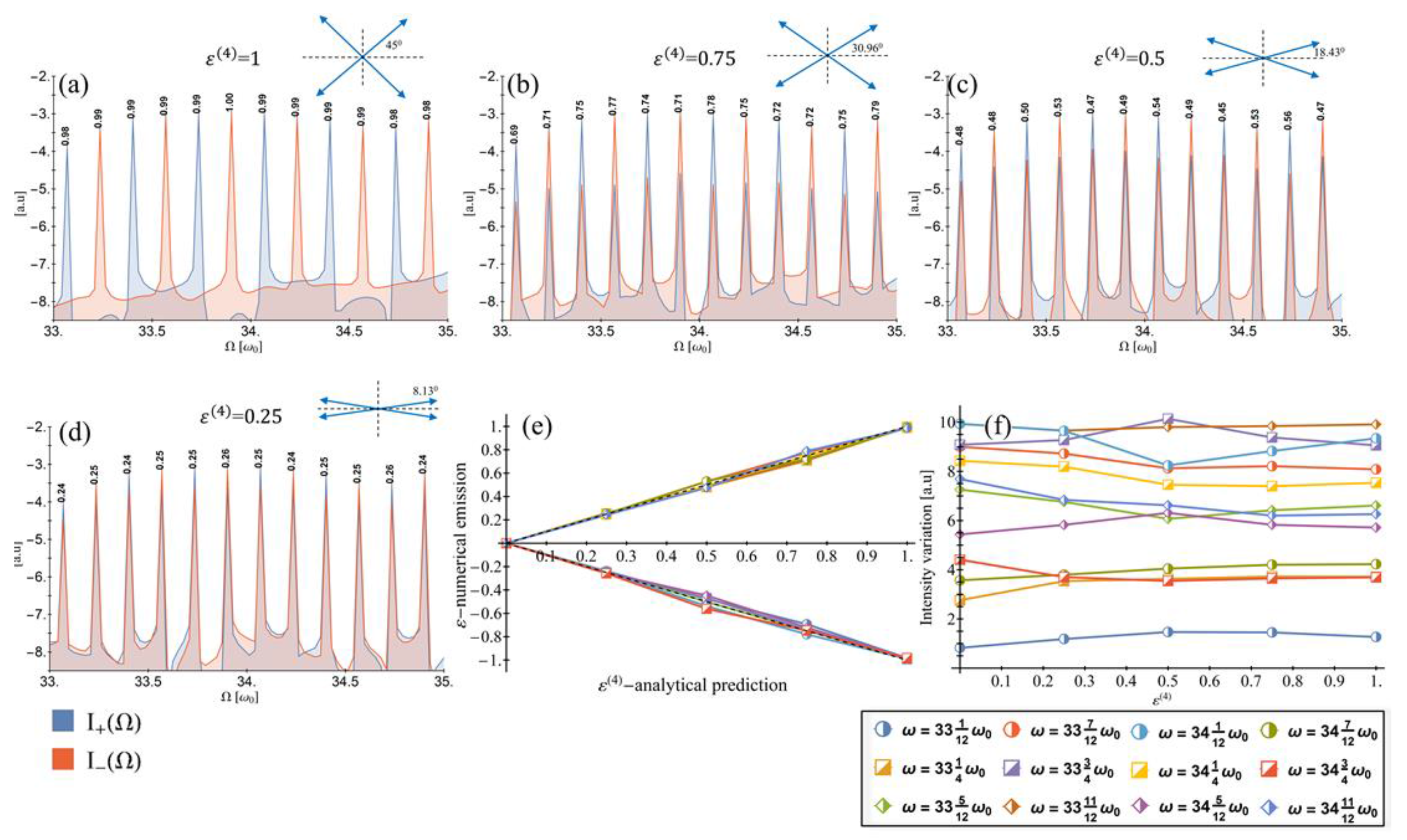
We solved the TDSE for the case of a driver field with circular DS ( e = 1 ) as given by Equation (2), and also for the non-circular case (e ≠ 1) for the scheme described by Equation (14). For all various degrees of freedom in the driver (parameters N, M, Np, and τ) the numerical spectra match the analytical model derived in Section 3. Simulations show harmonic emission at identical frequencies to those derived analytically in Equation (12). In terms of the ellipticity of the emitted harmonics, for the case of e = 1 all harmonics are fully circular (as seen in Figure 5a). For the non-circular case (e ≠ 1), the ellipticity closely follows the results of the analytical derivation of Section 3.2, and varies from 1 to 0 continuously (as seen in Figure 5a–e). The simplicity of our analytical model is a consequence of the temporal separation of the groups of “linear” HHG events from each pulse within the burst. Hence, the major features in the scheme allowing efficient harmonic polarization control result from simple interference phenomena. Significantly, the case of N = 4 presented in Figure 5, exhibits a “clean” spectrum that contains only the desired elliptical peaks, as expected from the analytical derivation. For other values of N, breaking the circular symmetry is accompanied by the appearance of new (previously forbidden) harmonic peaks, which radiate weakly. However, for N = 4 a 2-fold rotational symmetry prevents this, meaning that no energy is wasted through new harmonic channels. The numerical variation in peak intensities can be seen in Figure 5f for a sample spectral region, and clearly show a minimal coupling between the intensity and the target ellipticity, all the way from fully circular to fully linear (up to ~10%).
Finally, we note that we tested our approach for initial states with nonzero orbital angular momentum (in such cases, the ω-2ω bi-circular scheme results with asymmetric spectra that prefer one circular polarization over the other [21,34,39,44]). We found that our approach does not depend on the initial state’s angular momentum, as long as the total valence electronic states angular momentum is zero, which makes sense because within each ionization-recollision-emission process the driving laser is linearly polarized.

5. Conclusions

We extended our recently proposed scheme for generation of bright helically polarized high harmonics [38]. We showed that a quasi-monochromatic linearly polarized pulse-burst drives circular HHG if the pulses polarization axes uphold an N-fold rotational DS (for N > 2). The harmonics are born in integer multiples of the frequency of the DS itself, which can be tuned by controlling the duration of the pulses in the burst, and their temporal separation. By rotating the polarization axes of the comprising pulses, the ellipticity of the harmonic spectrum can be finely-tuned (collectively) from fully circular, through elliptical, to linear. We investigated the method from a time-domain perspective, as well as a photonic perspective, and showed the energy and spin-angular momentum conservation laws are upheld. We showed that HHG with this method is mathematically equivalent to N-slit diffraction, where the allowed harmonics and their respectful polarization is determined by the interference of N successive linearly-polarized harmonic spectra. Importantly, we found that the case of N = 4 yields an optimal elliptical harmonic spectrum for any target ellipticity, with a maximal conversion efficiency. Our method could open up a wide range of applications in coherent control and ultrafast chiral spectroscopy for processes with narrow resonances and above 10 fs durations (e.g., X-ray magnetic circular dichroism measurements [27], and spin-flipping in magnetic materials [45]). Furthermore, it may find use in HHG-based ellipsometry [37].

Acknowledgments

This work was supported by the Israel Science Foundation (grant No. 1225/14), the Israeli Center of Research Excellence ‘Circle of Light’ supported by the I-CORE Program of the Planning and Budgeting Committee and the Israel Science Foundation (grant No. 1802/12), and the Wolfson foundation. O.N. gratefully acknowledges the support of the Adams Fellowship Program of the Israel Academy of Sciences and Humanities.

Author Contributions

All authors contributed significantly to the reported research.

Conflicts of Interest

The authors declare no conflict of interest.

References

  1. Ferray, M.; L’Huillier, A.; Li, X.F.; Lompre, L.A.; Mainfray, G.; Manus, C. Multiple-harmonic conversion of 1064 nm radiation in rare gases. J. Phys. B At. Mol. Opt. Phys. 1988, 21, L31–L35. [Google Scholar] [CrossRef]
  2. Li, X.F.; L’Huillier, A.; Ferray, M.; Lompré, L.A.; Mainfray, G. Multiple-harmonic generation in rare gases at high laser intensity. Phys. Rev. A 1989, 39, 5751–5761. [Google Scholar] [CrossRef]
  3. Corkum, P.B. Plasma perspective on strong field multiphoton ionization. Phys. Rev. Lett. 1993, 71, 1994–1997. [Google Scholar] [CrossRef] [PubMed]
  4. Lewenstein, M.; Balcou, P.; Ivanov, M.Y.; L’Huillier, A.; Corkum, P.B. Theory of high-harmonic generation by low-frequency laser fields. Phys. Rev. A 1994, 49, 2117–2132. [Google Scholar] [CrossRef] [PubMed]
  5. Ben-Tal, N.; Moiseyev, N.; Beswick, A. The effect of Hamiltonian symmetry on generation of odd and even harmonics. J. Phys. B At. Mol. Opt. Phys. 1993, 26, 3017–3024. [Google Scholar] [CrossRef]
  6. Alon, O.E.; Averbukh, V.; Moiseyev, N. Selection Rules for the High Harmonic Generation Spectra. Phys. Rev. Lett. 1998, 80, 3743–3746. [Google Scholar] [CrossRef]
  7. Antoine, P.; Carré, B.; L’Huillier, A.; Lewenstein, M. Polarization of high-order harmonics. Phys. Rev. A 1997, 55, 1314–1324. [Google Scholar] [CrossRef]
  8. Weihe, F.A.; Dutta, S.K.; Korn, G.; Du, D.; Bucksbaum, P.H.; Shkolnikov, P.L. Polarization of high-intensity high-harmonic generation. Phys. Rev. A 1995, 51, R3433–R3436. [Google Scholar] [CrossRef] [PubMed]
  9. Strelkov, V.V.; Gonoskov, A.A.; Gonoskov, I.A.; Ryabikin, M.Y. Origin for ellipticity of high-order harmonics generated in atomic gases and the sublaser-cycle evolution of harmonic polarization. Phys. Rev. Lett. 2011, 107, 043902. [Google Scholar] [CrossRef] [PubMed]
  10. Kanai, T.; Minemoto, S.; Sakai, H. Ellipticity dependence of high-order harmonic generation from aligned molecules. Phys. Rev. Lett. 2007, 98, 053002. [Google Scholar] [CrossRef] [PubMed]
  11. Möller, M.; Cheng, Y.; Khan, S.D.; Zhao, B.; Zhao, K.; Chini, M.; Paulus, G.G.; Chang, Z. Dependence of high-order-harmonic-generation yield on driving-laser ellipticity. Phys. Rev. A 2012, 86, 011401. [Google Scholar] [CrossRef]
  12. Long, S.; Becker, W.; McIver, J.K. Model calculations of polarization-dependent two-color high-harmonic generation. Phys. Rev. A 1995, 52, 2262–2278. [Google Scholar] [CrossRef] [PubMed]
  13. Tong, X.-M.; Chu, S.-I. Generation of circularly polarized multiple high-order harmonic emission from two-color crossed laser beams. Phys. Rev. A 1998, 58, R2656. [Google Scholar] [CrossRef]
  14. Xie, X.; Scrinzi, A.; Wickenhauser, M.; Baltuška, A.; Barth, I.; Kitzler, M. Internal momentum state mapping using high harmonic radiation. Phys. Rev. Lett. 2008, 101, 033901. [Google Scholar] [CrossRef] [PubMed]
  15. Yuan, K.-J.; Bandrauk, A.D. Generation of circularly polarized attosecond pulses by intense ultrashort laser pulses from extended asymmetric molecular ions. Phys. Rev. A 2011, 84, 023410. [Google Scholar] [CrossRef]
  16. Liu, L.Z.; O’Keeffe, K.; Hooker, S.M. Optical rotation quasi-phase-matching for circularly polarized high harmonic generation. Opt. Lett. 2012, 37, 2415–2417. [Google Scholar] [CrossRef] [PubMed]
  17. Liu, C.; Nisoli, M. Control of the polarization of isolated attosecond pulses in atoms with nonvanishing angular quantum number. Phys. Rev. A 2012, 85, 013418. [Google Scholar] [CrossRef]
  18. Yuan, K.-J.; Bandrauk, A.D. Circularly polarized attosecond pulses from molecular high-order harmonic generation by ultrashort intense bichromatic circularly and linearly polarized laser pulses. J. Phys. B At. Mol. Opt. Phys. 2012, 45, 074001. [Google Scholar] [CrossRef]
  19. Yuan, K.J.; Bandrauk, A.D. Single circularly polarized attosecond pulse generation by intense few cycle elliptically polarized laser pulses and terahertz fields from molecular media. Phys. Rev. Lett. 2013, 110, 023003. [Google Scholar] [CrossRef] [PubMed]
  20. Fleischer, A.; Sidorenko, P.; Cohen, O. Generation of high-order harmonics with controllable elliptical polarization. Opt. Lett. 2013, 38, 223–225. [Google Scholar] [CrossRef] [PubMed]
  21. Medišauskas, L.; Wragg, J.; Van Der Hart, H.; Ivanov, M.Y. Generating Isolated Elliptically Polarized Attosecond Pulses Using Bichromatic Counterrotating Circularly Polarized Laser Fields. Phys. Rev. Lett. 2015, 115, 153001. [Google Scholar] [CrossRef] [PubMed]
  22. Reich, D.M.; Madsen, L.B. A Rotating-Frame Perspective on High-Harmonic Generation of Circularly Polarized Light. Phys. Rev. A 2016, 93, 043411. [Google Scholar] [CrossRef]
  23. Zhou, X.; Lock, R.; Wagner, N.; Li, W.; Kapteyn, H.C.; Murnane, M.M. Elliptically polarized high-order harmonic emission from molecules in linearly polarized laser fields. Phys. Rev. Lett. 2009, 102, 073902. [Google Scholar] [CrossRef] [PubMed]
  24. Mairesse, Y.; Higuet, J.; Dudovich, N.; Shafir, D.; Fabre, B.; Mével, E.; Constant, E.; Patchkovskii, S.; Walters, Z.; Ivanov, M.Y.; et al. High harmonic spectroscopy of multichannel dynamics in strong-field ionization. Phys. Rev. Lett. 2010, 104, 213601. [Google Scholar] [CrossRef] [PubMed]
  25. Vodungbo, B.; Barszczak Sardinha, A.; Gautier, J.; Lambert, G.; Valentin, C.; Lozano, M.; Iaquaniello, G.; Delmotte, F.; Sebban, S.; Lüning, J.; et al. Polarization control of high order harmonics in the EUV photon energy range. Opt. Express 2011, 19, 4346–4356. [Google Scholar] [CrossRef] [PubMed]
  26. Fleischer, A.; Kfir, O.; Diskin, T.; Sidorenko, P.; Cohen, O. Spin angular momentum and tunable polarization in high-harmonic generation. Nat. Photonics 2014, 8, 543–549. [Google Scholar] [CrossRef]
  27. Kfir, O.; Grychtol, P.; Turgut, E.; Knut, R.; Zusin, D.; Popmintchev, D.; Popmintchev, T.; Nembach, H.; Shaw, J.M.; Fleischer, A.; et al. Generation of bright phase-matched circularly-polarized extreme ultraviolet high harmonics. Nat. Photonics 2014, 9, 99–105. [Google Scholar] [CrossRef]
  28. Ferré, A.; Handschin, C.; Dumergue, M.; Burgy, F.; Comby, A.; Descamps, D.; Fabre, B.; Garcia, G.A.; Géneaux, R.; Merceron, L.; et al. A table-top ultrashort light source in the extreme ultraviolet for circular dichroism experiments. Nat. Photonics 2014, 9, 93–98. [Google Scholar] [CrossRef]
  29. Lambert, G.; Vodungbo, B.; Gautier, J.; Mahieu, B.; Malka, V.; Sebban, S.; Zeitoun, P.; Luning, J.; Perron, J.; Andreev, A.; et al. Towards enabling femtosecond helicity-dependent spectroscopy with high-harmonic sources. Nat. Commun. 2015, 6, 6167. [Google Scholar] [CrossRef] [PubMed]
  30. Hickstein, D.D.; Dollar, F.J.; Grychtol, P.; Ellis, J.L.; Knut, R.; Hernández-García, C.; Zusin, D.; Gentry, C.; Shaw, J.M.; Fan, T.; et al. Non-collinear generation of angularly isolated circularly polarized high harmonics. Nat. Photonics 2015, 9, 743–750. [Google Scholar] [CrossRef]
  31. Fan, T.; Grychtol, P.; Knut, R.; Hernández-García, C.; Hickstein, D.D.; Zusin, D.; Gentry, C.; Dollar, F.J.; Mancuso, C.A.; Hogle, C.W.; et al. Bright circularly polarized soft X-ray high harmonics for X-ray magnetic circular dichroism. Proc. Natl. Acad. Sci. USA 2015, 112, 14206–14211. [Google Scholar] [CrossRef] [PubMed]
  32. Kfir, O.; Grychtol, P.; Turgut, E.; Knut, R.; Zusin, D.; Fleischer, A.; Bordo, E.; Fan, T.; Popmintchev, D.; Popmintchev, T.; et al. Helicity-selective phase-matching and quasi-phase matching of circularly polarized high-order harmonics: Towards chiral attosecond pulses. J. Phys. B At. Mol. Opt. Phys. 2016, 49, 123501. [Google Scholar] [CrossRef]
  33. Chen, C.; Tao, Z.; Hernández-García, C.; Matyba, P.; Carr, A.; Knut, R.; Kfir, O.; Zusin, D.; Gentry, C.; Grychtol, P.; et al. Tomographic reconstruction of circularly polarized high-harmonic fields: 3D attosecond metrology. Sci. Adv. 2016, 2, e1501333. [Google Scholar] [CrossRef] [PubMed]
  34. Baykusheva, D.; Ahsan, M.S.; Lin, N.; Wörner, H.J. Bicircular High-Harmonic Spectroscopy Reveals Dynamical Symmetries of Atoms and Molecules. Phys. Rev. Lett. 2016, 116, 123001. [Google Scholar] [CrossRef] [PubMed]
  35. Kfir, O.; Bordo, E.; Ilan Haham, G.; Lahav, O.; Fleischer, A.; Cohen, O. In-line production of a bi-circular field for generation of helically polarized high-order harmonics. Appl. Phys. Lett. 2016, 108, 211106. [Google Scholar] [CrossRef]
  36. Tompkins, H.; Irene, E.A. Handbook of Ellipsometry; William Andrew: Norwich, NY, USA, 2005. [Google Scholar]
  37. Brimhall, N.; Herrick, N.; Allred, D.D.; Turley, R.S.; Ware, M.; Peatross, J. Characterization of optical constants for uranium from 10 to 47 nm. Appl. Opt. 2010, 49, 1581–1585. [Google Scholar] [CrossRef] [PubMed]
  38. Neufeld, O.; Bordo, E.; Fleischer, A.; Cohen, O. High harmonic generation with fully tunable polarization by train of linearly-polarized pulses. New J. Phys. 2017, 19, 023051. [Google Scholar] [CrossRef]
  39. Milošević, D.B. Circularly polarized high harmonics generated by a bicircular field from inert atomic gases in the p state: A tool for exploring chirality-sensitive processes. Phys. Rev. A 2015, 92, 43827. [Google Scholar] [CrossRef]
  40. Barth, I.; Lein, M. Numerical verification of the theory of nonadiabatic tunnel ionization in strong circularly polarized laser fields. J. Phys. B At. Mol. Opt. Phys. 2014, 47, 204016. [Google Scholar] [CrossRef]
  41. Fleck, J.A.; Morris, J.R.; Feit, M.D. Time-dependent propagation of high energy laser beams through the atmosphere. Appl. Phys. 1976, 10, 129–160. [Google Scholar] [CrossRef]
  42. Feit, M.D.; Fleck, J.A.; Steiger, A. Solution of the Schrödinger equation by a spectral method. J. Comput. Phys. 1982, 47, 412–433. [Google Scholar] [CrossRef]
  43. Burnett, K.; Reed, V.C.; Cooper, J.; Knight, P.L. Calculation of the background emitted during high-harmonic generation. Phys. Rev. A 1992, 45, 3347–3349. [Google Scholar] [CrossRef] [PubMed]
  44. Dejan, B. Milošević Generation of elliptically polarized attosecond pulse trains. Opt. Lett. 2015, 40, 2381–2384. [Google Scholar]
  45. Radu, I.; Vahaplar, K.; Stamm, C.; Kachel, T.; Pontius, N.; Durr, H.A.; Ostler, T.A.; Barker, J.; Evans, R.F.L.; Chantrell, R.W.; et al. Transient ferromagnetic-like state mediating ultrafast reversal of antiferromagnetically coupled spins. Nature 2011, 472, 205–208. [Google Scholar] [CrossRef] [PubMed]
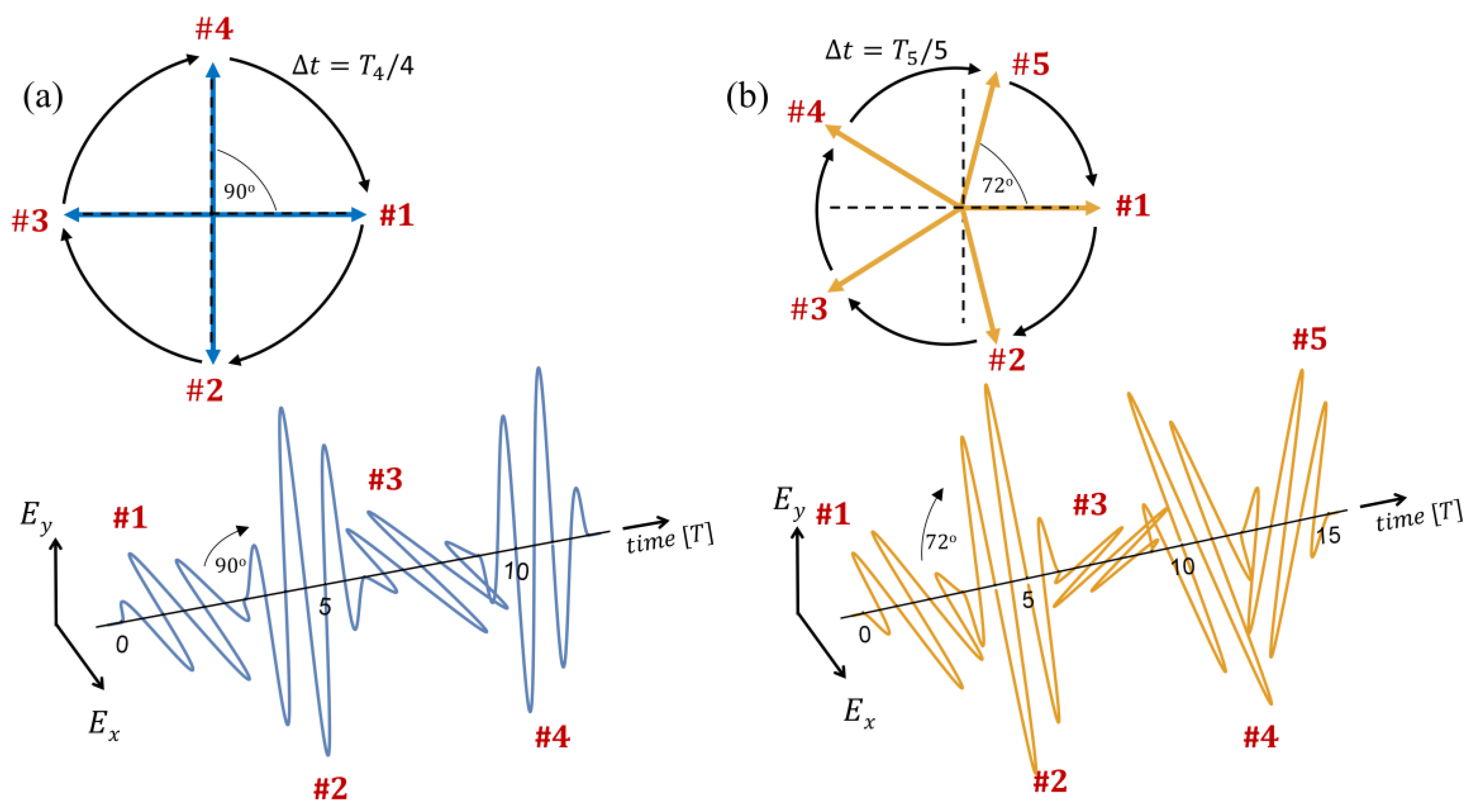
Figure 1. Example driving laser burst of linearly-polarized pulses according to Equation (2). (a) N = 4, M = 1, Np = 2, τ = 0; (b) N = 5, M = 1, Np = 2, τ = 0. In (a) and (b), A(t) is taken as a trapezoidal envelope with a rise and drop of one optical cycle long. Front view (Lissajous curve) of the pulse-burst is shown in inset, each arrow represents a linearly-polarized pulse within the burst. The pulses are numbered in red according to their chronological order.
Photonics 04 00031 g001
Figure 2. Analytically calculated spectral power and relative intensity of left and right circular spectral components according to Equation (11) for several values of parameters. (a) N = 4, M = 3, Np = 2, τ = 0; (b) N = 4, M = 3, Np = 2, τ = 5.25; (c) N = 5, M = 1, Np = 2, τ = 0; (d) N = 5, M = 3, Np = 2, τ = 0. The spectra are shown for representative harmonic orders 20–22 since within the analytical model the spectrum is repetitive due to the delta function responses.
Photonics 04 00031 g002
Figure 3. Analytical model for N’th order ellipticity control schemes for N = 3–9. The plot shows the deviation of the scheme progression parameter, e, from the ellipticity ε ( N ) (calculated according to Equations (14) and (15)), where the respective N value is given above each curve. For large values of N the ellipticity closely follows a linear dependence on the scheme progression parameter, e, with continuous control over the polarization of the emitted spectrum, from linear, through elliptic, to fully circular. The inset above the plot shows schematically how the pulses in the burst are rotated upon the variation of e in a manner that is symmetric about the x-axis. Arrows represent the original polarization axis of the pulses in the symmetric case yielding circular harmonics, and black arrows the direction in which these are rotated.
Photonics 04 00031 g003
Figure 4. Analytically calculated spectral power of the driver field (Equation (17)), with left and right circular spectral components for: (a) N = 3, M = 3, Np = 2, τ = 0; and (b) N = 9, M = 3, Np = 2, τ = 0. Power is displayed in logarithmic scale.
Photonics 04 00031 g004
Figure 5. Numerical time dependent Schrödinger equation (TDSE) simulations for: N = 4, M = 3, Np = 2, τ = 0, I0 = 3 × 10¹⁴ W/cm2, and λ = 800 nm, where the relative angle is changed according to Equation (14) to give a target ellipticity of: (a) ε(4) = 1; (b) ε(4) = 0.75; (c) ε(4) = 0.5; (d) ε(4) = 0.25. In each case the target ellipticity should be identical in all peaks in the spectrum. A Lissajous curve describing the shape of the pulse-burst is shown in inset, where blue arrows represent the linearly-polarized pulses in the burst. The numerically calculated ellipticity is indicated in black on top of each spectral peak. The spectra are presented for a selected region in the plateau 33–35ω0. (e) Ellipticity calculated numerically for each peak in the same spectral region compared to the analytically predicted ellipticity from Equation (16), linear line indicated in dashed black. (f) The intensity variation for all the peaks in the same spectral region as a function of target ellipticity, showing minimal coupling of ellipticity and yield.
Photonics 04 00031 g005