Abstract
A thermally tunable 1 × 4 channel optical demultiplexer was designed using an ultra low-loss Si3N4 (propagation loss ~3.1 dB/m) waveguide. The demultiplexer has three 2 × 2 Mach-Zehnder interferometers (MZI), where each of the MZI contains two 2 × 2 general interference based multimode interference (MMI) couplers. The MMI couplers exhibit −3.3 dB to −3.7 dB power division ratios over a 50 nm wavelength range from 1530 nm to 1580 nm. The chrome-based (Cr) heaters placed on the delay arms of the MZI filters enable thermal tuning to control the optical phase shift in the MZI delay arms. This facilitates achieving moderately low crosstalk (14.5 dB) between the adjacent channels. The optical insertion loss of the demultiplexer per channel is between 1.5 dB to 2.2 dB over the 1550 nm to 1565 nm wavelength range. Error free performance (BER of 10−12) is obtained for all four 40 Gb/s data rate channels. The optical demultiplexer is an important tool towards building photonic integrated circuits with complex optical signal processing functionalities in the low-loss Si3N4 waveguide platform.
1. Introduction
The growth of internet traffic over the last decade has pushed data capacity and increased the processing speed demand in modern computational server based networks such as data centers. Optical interconnection between the servers of the data centers can further enhance the data processing capacity of the network by exploiting space, time, and wavelength domains [1,2,3]. An important challenge is to design photonic integrated circuits (PIC) with complex optical signal processing functionalities such that many of the data processing tasks can be transferred from the electrical to the optical domain. PICs using low-loss optical waveguide on Si3N4 [4] platform technology are a promising solution to implement some complex optical functionalities on-chip such as generating large optical time delay (i.e., by using optical buffers [5]) or building high quality factor resonators [6].
Propagation losses of 2.8 µm × 80 nm cross-section area Si3N4 waveguides first reported in [7] were measured to be 8 dB/m (0.5 mm bend radius), and as low as 3 dB/m for larger bends (2 mm bend radius). Large bend radius is required in the low-loss Si3N4 waveguide to reduce the mode-mismatch loss at the bending regions. Therefore, in the PIC applications, where compact waveguide routing is required, high index contrast waveguides, such as silicon on insulator (SOI) waveguides are preferable to Si3N4 waveguides. Standard SOI waveguides (220 nm × 500 nm cross-section area) with propagation losses of ~2.5 dB/cm have been demonstrated with bending radii as low as 7 µm [8]. However, to design optical buffer circuits using long length delay waveguides (i.e., in the range of meters to introduce several ns time delay [1,5]), SOI waveguides are not suitable. For example, to design the 12.86 ns delay line demonstrated in [5], a ~0.92 m long 220 nm × 500 nm cross-section SOI waveguide will exhibit around ~230 dB loss. Therefore, recently demonstrated low-loss Si3N4 waveguides are investigated to build integrated long optical buffers. Using a wafer-bonded silica-on-silicon planar waveguide platform, propagation losses as low as 0.1 dB/m are reported in [9], where the waveguide thickness is set to 40 nm and the waveguide width varies from 3 µm to 14 µm. The low trending propagation loss of Si3N4 waveguides suggests that these waveguides can be used to build all optical packet routing PICs where long optical delay lines or low-loss optical buffer circuits are required [10]. In [1], for example, we proposed an analytical model of a passive wavelength striped (PWM) circuit, where an optical serial packet stream is converted to a parallel stream to increase the bandwidth scalability of optical interconnect networks. The PWM circuit implements simultaneous optical filtering and delays each time segment of the data with respect to its adjacent channel by a specific amount of time using optical buffers or long optical delay waveguides. To design an integrated version of the PWM circuit, low-loss Si3N4 waveguides can be used to build its key building blocks (i.e., a demultiplexer to filter the optical channels and the long delay lines to implement the time delay between the adjacent channels). A low-loss arrayed-waveguide grating (AWG) demultiplexer using Si3N4 waveguide platform is proposed in [11]. An AWG based demultiplexer on Si3N4 waveguide platform presented in [11] (<0.5 dB insertion loss and 40 dB cross-talk) demonstrates better performance than the MZI filter based optical demultiplexers. However, in [1] we find that the AWG approach to build the demultiplexer in a PWM circuit incurs overall greater loss and increases the footprint of the PWM device due to the individual time delay requirements for each of the channels after the AWG. MZI based demultiplexers can solve this problem by simultaneously filtering and delaying the optical channels with respect to their adjacent channels. In addition to this, some optical signal processing circuits require MZI based lattice filter architecture such that filter parameters can be tuned (electro-optically or thermo-optically) to generate tunable optical signals [12]. Therefore, MZI based thermally tunable wavelength demultiplexer is an important device which adds more functionalities or tunability in the low-loss Si3N4 delay waveguide based components. For the applications where large optical time delays are required in addition to the wavelength filtering, the AWG based multiplexer and MZI filter based demultiplexer can be used together to build the complete PIC on chip [1].
In this paper, we present the analysis and experimental results of a 1 × 4 channel MZI based wavelength demultiplexer designed using the 2.8 µm × 72 nm cross-section area Si3N4 waveguide. The waveguide has a SiO2 substrate and a plasma-enhanced chemical vapor deposition (PECVD) SiO2 upper cladding, where the thickness of both layers is 15 μm. The demultiplexer is fabricated using the TriPleX photonic platform [13] from LioniX BV. Performance result of the general interference based 2 × 2 MMI couplers used to build the MZ interferometers shows −3.3 dB to −3.7 dB power division ratio over 50 nm wavelength range from 1530 nm to 1580 nm. We have measured 1 × 10−12 bit error rate (BER) for all of the four demultiplexed 40 Gb/s data rate channels after electrically time demultiplexing them at a 10 Gb/s rate.
2. Design of the 1 × 4 Channel Wavelength Demultiplexer
In this section, we first describe the structure and properties of the low-loss 2.8 µm × 72 nm cross-section area Si3N4 waveguide. Next we will present the simulation method and results used to design the MMI couplers and the overall MZI based demultiplexer.
2.1. Low-Loss Si3N4 Waveguide
The low-loss single stripe geometry Si3N4 waveguide from the TriPleX photonic platform [13] was chosen to design the photonic components presented in this paper. The waveguide fabrication process is similar to the methods reported in [4]. The width and height of the waveguide was chosen such that minimum propagation loss is achieved at the bending radius equal to or more than 4 mm. The cross-section area of the waveguide is shown in Figure 1a. Figure 1b shows the TE mode profile of the optical waveguide obtained from 2D finite-difference time-domain (FDTD) simulation using the Lumerical Mode software.
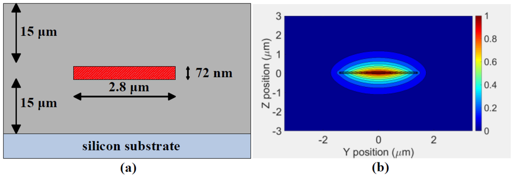
Figure 1.
(a) Cross-section (not to scale) of the single stripe geometry Si3N4 waveguide, (b) Simulated TE mode profile (in linear scale) at 1550 nm wavelength, where the 72 nm thick Si3N4 waveguide is superimposed (drawn to scale).
We calculate the effective index (neff) and group index (ng) of the waveguide using the 2D FDTD method over the wavelength range from 1530 nm to 1580 nm. Figure 2a,b shows that the effective index and group index of the waveguide varies by Δneff = −0.0015 and Δng = −0.006, respectively, over the wavelength range from 1530 nm to 1580 nm. The change in both the effective index and in the group index of the waveguide with respect to the wavelength results in a wavelength dependency in the transmission response of the demultiplexer, which will be discussed in Section 3.2.
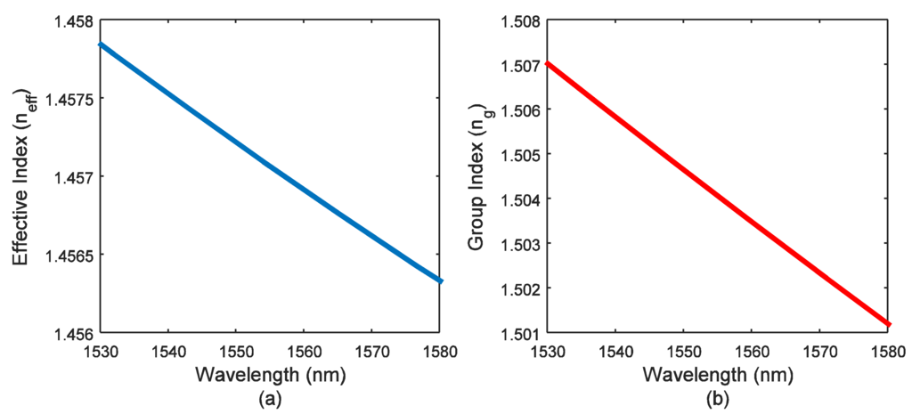
Figure 2.
Variation in the (a) effective index (neff) and (b) group index (ng) of the Si3N4 waveguide from the wavelength range from 1530 nm to 1580 nm.
2.2. Design of the 2 × 2 MMI Coupler
The general interference based 2 × 2 MMI couplers were used to build the MZ interferometers of the demultiplexer. It is necessary to perform numerical simulations to accurately estimate the core waveguide length (“LMMI”) of a MMI coupler for a given core waveguide width [14]. In this work, we use FDTD simulation from Lumerical Mode software to estimate the core MMI waveguide length “LMMI”. Figure 3a shows the waveguide geometries of the 2 × 2 MMI coupler designed in this work. The core waveguide width (WMMI = 30 µm) was chosen to make the lateral separation between the two input waveguides and between the two output waveguides large enough (“Llat” = 10 µm) such that no inter-coupling occurs between the two side-by-side I/P waveguides. The access waveguide width (Wa) is increased to 5 µm to minimize the mode mismatch loss at MMI core waveguide input and output edges [14]. A 200 µm long taper waveguide is designed to lower optical loss transition from the 5 µm wide waveguide to the 2.8 µm wide waveguide. Figure 3b shows the electric field distribution (in linear scale) in a 2D plane of the MMI coupler for a MMI core waveguide length of LMMI ≈ 1860 µm at 1550 nm wavelength.
To determine the effect of the variation in the MMI coupler length on the insertion loss and the power coupling between the two output (O/P) ports of the MMI coupler, we have simulated three MMI structures with different core waveguide lengths, while keeping the core waveguide width fixed to WMMI = 30 µm. Table 1 shows that at 1550 nm wavelength, MMI coupler with the core waveguide length LMMI ≈ 1860 µm exhibits minimum insertion loss per O/P waveguide (~0.3 dB).

Figure 3.
(a) Schematic of the 2 × 2 multimode interference (MMI) coupler with taper waveguide length, Ltaper = 200 µm and access waveguide width, Wa = 5 µm and (b) the electric field distribution in a 2D plane of the MMI coupler at 1550 nm wavelength.

Table 1.
Simulation values of the power coupled to the two O/P waveguides of the MMI coupler.
| LMMI (µM) | Percentage of the Input Power Coupled to the Two O/P Waveguides | Input Power Coupled to the Two O/P Waveguides (dB) | ||
|---|---|---|---|---|
| O/P 1 | O/P 2 | O/P 1 | O/P 2 | |
| 1850 | 42% | 40% | −3.76 | −3.97 |
| 1860 | 47.1% | 46.5% | −3.27 | −3.32 |
| 1870 | 43% | 42.5% | −3.66 | −3.71 |
2.3. MZI Based 1 × 4 Channel Wavelength Demultiplexer
Figure 4 shows the schematic of the proposed demultiplexer architecture. The demultiplexer is designed to filter four 40 Gb/s data rate channels, where the wavelength separation between the adjacent channels is 3.2 nm. Therefore, in the demultiplexer structure shown in Figure 4, each of the four output channels is designed to have 4 × 3.2 nm = 12.8 nm free spectral range (FSR) in its corresponding optical spectrum. The detailed design method of the MZI based optical demultiplexer/filter can be found in [15,16]. In addition to the extra delay lengths (L1, L2 and L3) each of the MZI filters contains two equal length s-shaped bend waveguides (= 25.13 mm long), with a bending radius of 4 mm. As shown in Figure 4, on top of these bend waveguides, 12 mm long heaters are situated for thermal heating. To achieve 12.8 nm FSR at the four output channels (ch-1, ch-2, ch-3 and ch-4) of the demultiplexer, the first MZI (MZI with the extra delay waveguide length, L1) is designed to have 6.4 nm FSR at its two output channels (A1 and A2), where the wavelength separation between the two channels is 3.2 nm. We have set the delay length, L1 = 249.5 μm in the first MZI to obtain FSR = 6.4 nm at its output channels (A1 and A2). The following equation is used to estimate the value of L1:
where, the group index, ng = 1.505 at λ = 1550 nm wavelength (from Figure 2b).
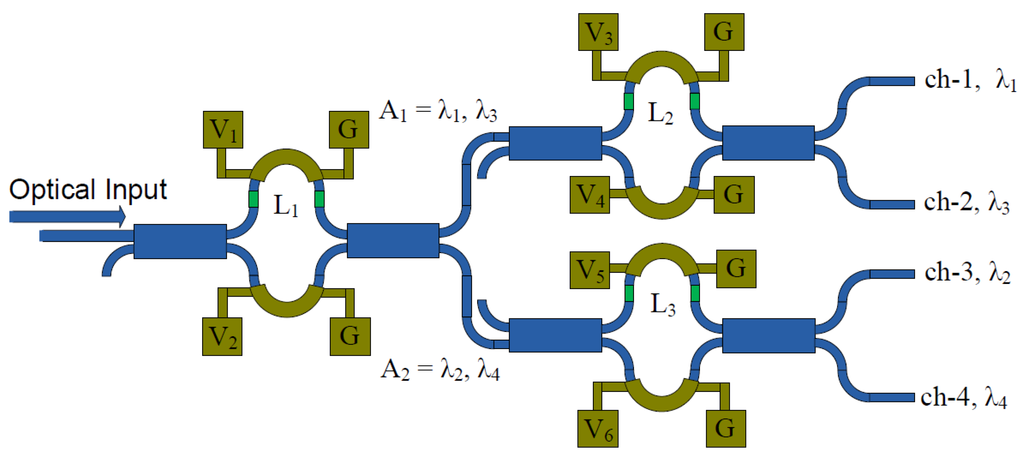
Figure 4.
Schematic of the 1 × 4 channel wavelength demultiplexer architecture with the integrated Cr heater on the delay arms of the Mach-Zehnder interferometer (MZI) (not to scale). V1 to V6: electrical pad to apply the DC voltages for thermal tuning, G: ground pad, L1 to L3: delay waveguide lengths (in green color).
The values of the delay waveguide lengths, L2 = 124.7 μm + Lπ/2 and L3 = 124.7 μm, are chosen such that the corresponding MZIs containing these delay lines have an FSR = 12.8 nm. Note that an extra delay length, Lπ/2 = 0.257 μm, is added to L2 in the second MZI, to induce a phase shift of π/2 in the optical signal of the corresponding delay arm. This extra π/2 phase shift is necessary to obtain the required wavelength separation of 3.2 nm and low crosstalk between the output channels ch-1 and ch-2. Figure 5a presents the simulation result of the overlapped optical transmission response of the four channels (ch-1, ch-2, ch-3 and ch-4) of the demultiplexer, where a ~15 dB crosstalk between the channels is obtained. We find that it is important to implement thermal tunability in the delay arms of the MZIs to ensure low crosstalk as well as the required channel separation between the output channels. As an example, a 100 nm length offset error is added in the simulation to all the three delay arms (L1 to L3) of the demultiplexer to assess the impact of fabrication error on the demultiplexer. From Figure 5b, it is clear that this error results in a significant degradation in the crosstalk performance of the demultiplexer (from 15 dB to 8 dB). The 100 nm length offset error induces 0.19π of phase error. It will be shown in Section 3 that the thermal heaters designed in this work, can compensate up to 0.5π of phase shift error at the expense of 150 mW (25 V, 6 mA) electrical power consumption. We have also investigated the effect of waveguide width variation on the phase shift between the two long delay arms (25.13 mm) of each MZI filter. As an example, we include a 2 nm width variation on the two delay arms (i.e., 2.8 µm and 2.802 µm wide) of each of the three MZI filters in the demultiplexer. From a similar mode simulation method described in Section 2.1, we find that for a 2.802 µm waveguide width, the group index increases by Δng = 1.55 × 10⁻⁵ at 1550 nm wavelength. The change in group index induces π/2 phase mismatch between the two 25.13 mm long delay waveguides which can be compensated by the thermal heaters. However, if the waveguide width variation is more than 2 nm over 25.13 mm long waveguide, the thermal heaters designed in this work cannot compensate for the phase error. However, the MZI delay waveguides are placed in proximity, and it is unlikely that two waveguides maintain such width difference over the 25.13 mm length. In fact, two delay waveguides in proximity are more likely to have the same width offset, which would induce near zero phase shift in the demultiplexer compensable by the thermal heaters.
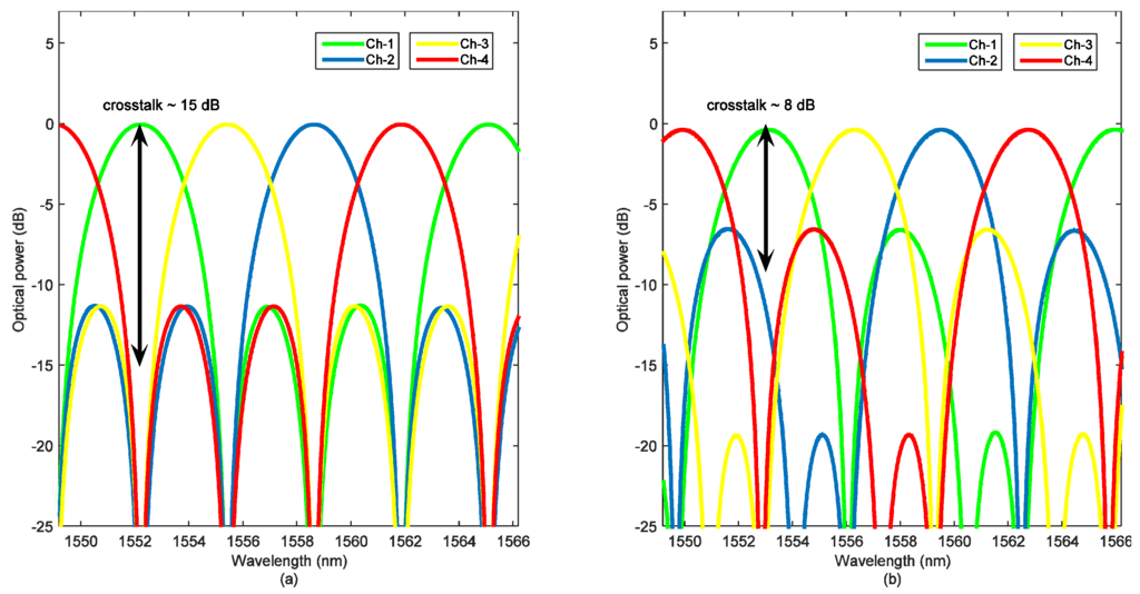
Figure 5.
Simulation result of the (a) overlapped transmission responses of the four optical output channels and (b) overlapped transmission responses of the four optical output channels in the presence of a delay length mismatch error 100 nm.
Thermal heaters were integrated on top of the MZI delay waveguides for tuning the phase of the optical signal upto π/2. As mentioned in the paragraph above, we have added an extra delay length of Lπ/2 = 0.257 μm to passively achieve the π/2 phase shift. Despite this delay, thermal heaters make the design of the demultiplexer more robust against fabrication variations. The electrical contact pads on the heaters were 2 mm × 0.5 mm in dimension with pitch = 1 mm (Figure 6a). The large separation between the contact pads will simplify and lower the cost of wire bonding to the chip. However, in this work we have applied electrical voltage to the heaters using external DC probes. We have used proprietary data from LioniX BV to keep the separation between the thermal heaters from 8 mm to 16 mm, to avoid thermal crosstalk (Figure 6b).
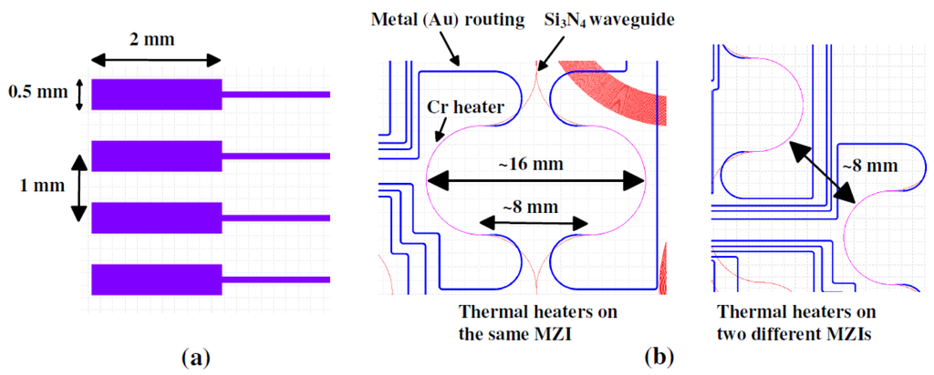
Figure 6.
(a) Dimension and vertical separation between the electrical contact pads, (b) Layout of the thermal heaters, minimum distance is kept to 8 mm to avoid thermal crosstalk.
3. Experiment Setup and Results
To determine the performance result of the 1 × 4 channel wavelength demultiplexer, first, we have measured the transmission responses of the different passive test devices which were designed on the same chip. The test devices include a 10 cm long Si3N4 waveguide having nine alternating bends of 4 mm bending radius, a spiral shaped 1.5 m long delay waveguide, a heater integrated Mach-Zehnder interferometer, and three test structures for MMI couplers with different core waveguide lengths. The 1.5 m long test delay waveguide has a 4 mm bending radius at the center and routing regions (Figure 7a). Several 10 cm long test structures were designed next to each of the test components. The transmission response of these test devices allowed us to determine the propagation loss of the Si3N4 waveguide and the insertion loss of the MMI couplers. These test results also facilitate assessing the insertion loss of each channel of the demultiplexer. We proceed to measure the BER performance of the demultiplexer.
Figure 7 shows the experimental setup used to measure the transmission response of the passive components. A continuous wave (CW) signal from a laser with an optical power of 10 dBm is connected to a polarization controller (PC) and tuned over the wavelength range from 1530 nm to 1580 nm. At the output of the polarization controller (PC), the measured optical power is around ~8.8 dBm. The polarized CW optical signal is applied to the input edge coupler (I/P) of the test device. The output optical power is measured for each of the test components and their corresponding 10 cm long test waveguide. The optical power transmitted through the 10 cm long test Si3N4 waveguide is subtracted from the output power of the other test devices such as the MMI couplers and wavelength demultiplexer to find their corresponding insertion loss. The distance between the i/o waveguide edges of the test components and the 10 cm long test waveguide at the polished facet was kept to 60 µm. This minimizes the error in measuring the test component’s insertion loss due to the variation in fiber to chip coupling loss.
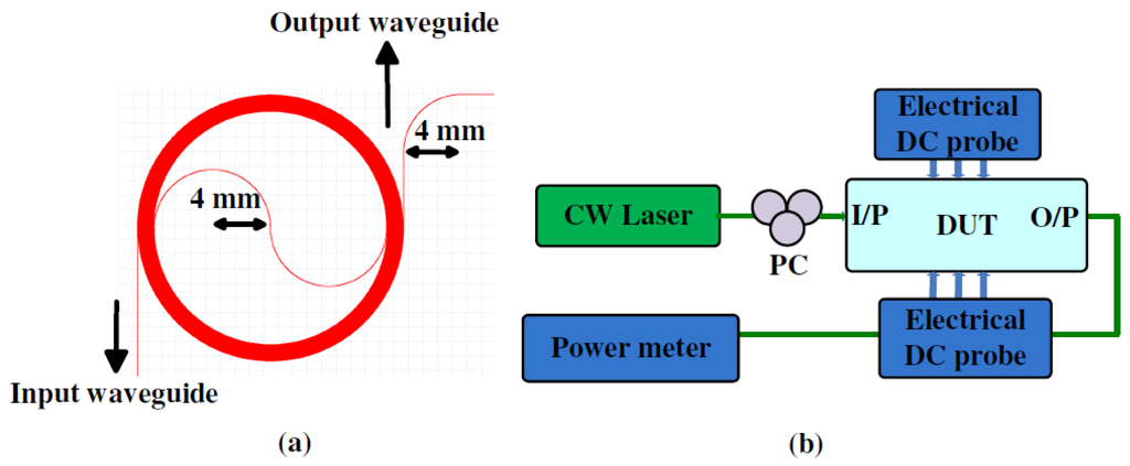
Figure 7.
(a) Layout of the 1.5 m long spiral waveguide, (b) Experimental setup to measure the transmission responses of the different test devices, (10 cm long waveguide, 1.5 m long spiral waveguide and the 1 × 4 channel wavelength demultiplexer).
Figure 8 shows the optical transmission response of the ~10 cm long straight waveguide and ~1.5 m long spiral delay waveguide. The optical coupling to the chip was implemented using two cleaved fibers at the input and output edge of the chip. It also shows the transmission response of the CW signal after the PC. From this figure it is seen that the total edge coupling in and out loss is around 9.8 dB (8.8–(−1) dBm) at the wavelength of 1550 nm, considering the propagation loss in the 10 cm long Si3N4 waveguide is negligible compared to the edge coupling loss. The measured coupling loss variation over all the 10 cm long waveguides is less than 0.05 dB. From Figure 8, it is also seen that the 1.5 m long spiral delay waveguide suffers an extra 4.6 dB optical loss compared to the 10 cm long Si3N4 waveguide. From this result, we measured an approximate 3.1 dB/m propagation loss for the 72 nm thick Si3N4 waveguide, where the total fiber to chip coupling loss is assumed to be 9.8 dB.
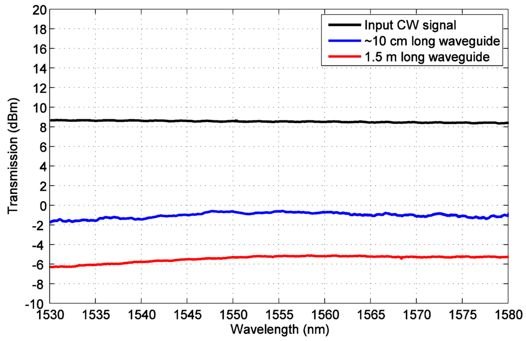
Figure 8.
Optical transmission response of the continuous wave (CW) signal from the laser, 10 cm long Si3N4 waveguide and 1.5 m long Si3N4 waveguide.
We have experimentally determined the group index of the 72 nm thick Si3N4 waveguide using the transmission response of a test Mach-Zehnder interferometer (MZI). The length difference between the two arms of the MZI is 4.4 mm (the two MZI arms are 12.26 mm and 16.66 mm in length). In addition to this, a ~12 mm long and 20 µm wide heater was placed on top of the longer arm of the MZI filter to find the Pπ (input power required at the heater to achieve π phase shift in the CW signal) of the heater. All the heaters in the 1 × 4 channel wavelength demultiplexer have similar geometry. It should be mentioned that the test MZI structure is similar to the MZI filters of the 1 × 4 channel wavelength demultiplexer shown in Figure 4. However, as mentioned in Section 2.3, the extra delay lengths in the MZI filters of the 1 × 4 channel wavelength demultiplexer is much smaller (i.e., L1 = 249.5 μm, L2 = 124.96 μm and L3 = 124.7 μm) compared to the extra delay length (4.4 mm) of the test MZI filter. Therefore, in the test MZI filter we expect to have smaller FSR, which will facilitate the experimental measurement of the group index of the waveguide within a small wavelength range. In both the test MZI and demultiplexer, Pπ of the heaters will be similar, as the heaters have same length (~12 mm) in all the MZI filters presented in this article. Figure 9a shows the zoomed optical transmission response of the test MZI structure, where the input CW signal from the laser with an optical power of 10 dBm is tuned over the wavelength range from 1547 nm to 1552 nm. We found that at a heater bias voltage of 25 V (6 mA), the optical transmission response of the filter shifts in wavelength by an amount equal to 1/4th of its FSR (0.09 nm). Therefore, the measured resistance and Pπ/2 is 4.17 kΩ and 150 mW, respectively, for the MZI delay arm’s heater. From this result, the approximate value of Pπ can be interpolated to be 300 mW. Next, we used the method provided in [17] to measure group index (ng) of the waveguide from the transmission response of the MZI. In this method, the measured FSR at different wavelengths is used to calculate the group index. Figure 9b shows the simulated and experimental value of the group index at wavelength near 1550 nm. From this figure, it is clear that the experimental value of the group index is within ~0.001 error limit from the simulation value. We calculated that within this error limit of the group index, the FSR of the filter would change by only ~0.003 nm. As the wavelength separation between the adjacent channels of the filter is 3.2 nm, this FSR variation due to this group index variation does not affect the filter performance.
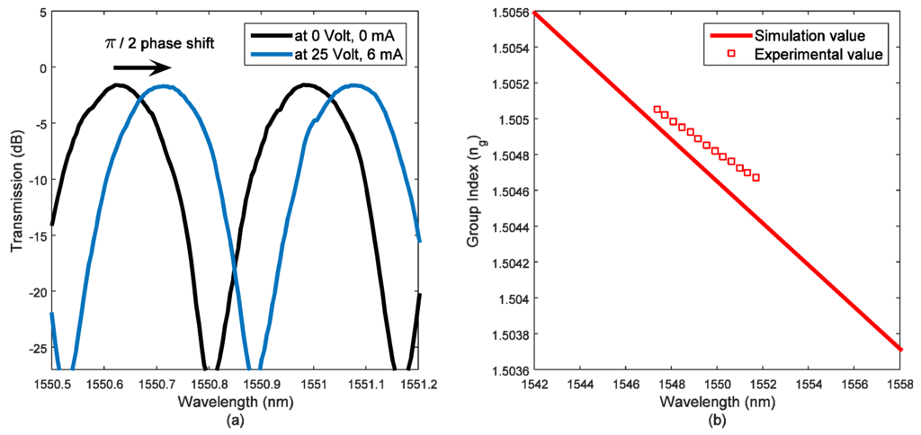
Figure 9.
(a) Optical transmission response of the test MZI filter at two different bias voltages to the heater, (b) Measured and calculated group index of the 72 nm thick Si3N4 waveguide.
3.1. Power Splitting Ratio in the Si3N4 Waveguide Based MMI Couplers
We assess the power splitting ratio in the two output arms of the MMI couplers. Three test MMI couplers were designed such that all the MMI couplers have the same core waveguide width (WMMI) of 30 µm. The core waveguide lengths (LMMI) of the three MMI couplers are varied from the first beat length (~1860 µm found from simulation, Section 2.2). Figure 10 shows the normalized output transmission response of the MMI couplers. From this figure, it is seen that optical power splitting ratio within 0.3 dB power range is obtained for all the MMI couplers at both ports. The MMI coupler with LMMI = 1860 µm exhibits 0.4 dB loss per output channel at 1550 nm wavelength. The optical loss per channel increases to 0.8 dB and 1 dB for the MMI couplers with ±10 µm variation from the simulated optimum core waveguide length. The 0.4 dB to 1 dB insertion loss for the MMI coupler is still high, considering the low-loss Si3N4 platform used to design the devices. This suggests that in future runs the MMI coupler should be designed more carefully by considering both the simulation and experimental result obtained from this run.
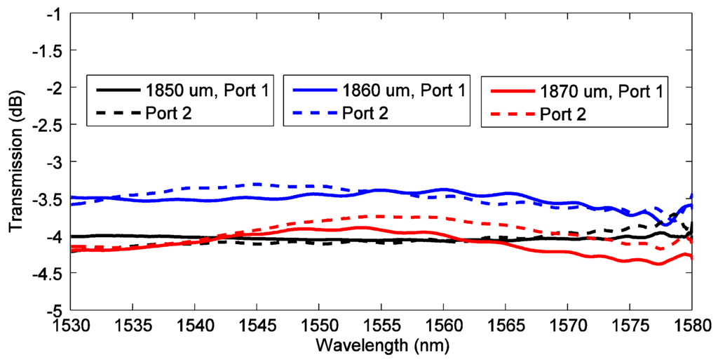
Figure 10.
Normalized output transmission response at the two output ports of the MMI couplers.
3.2. Transmission Response of the Four Channel Wavelength Demultiplexer
To determine the insertion loss and crosstalk between the adjacent channels of the 1 × 4 channel demultiplexer, we have used a similar setup as in Figure 7b. The optical phase shift in the delay arms of the MZI interferometers was thermally tuned. We applied a set of DC voltages to implement thermal heating in the corresponding delay arms. The thermal heating occurs from the electrical power loss in the resistive load of the heater. Figure 11 shows the optical transmission response of each of the four channels of the demultiplexer. The applied DC voltages in the thermal heaters of the delay arms were V2 = 1.5 V (0.32 mA), V3 = 4 V (0.9 mA) and V5 = 2.5 V (0.55 mA). All the voltages were applied simultaneously to the heaters to minimize the crosstalk between the channels. Each of the heaters has separate signal and ground contact pads, therefore no electrical cross-talk was observed in the simultaneous biasing. From this figure it is seen that the side lobe suppression ratio for ch-1, ch-2, ch-3 and ch-4 are 12 dB, 12.8 dB, 12.6 dB and 11.2 dB, respectively from 1530 nm to 1580 nm wavelength range. The free spectral range (FSR) from 1550 nm to 1580 nm wavelength range for ch-1, ch-2, ch-3 and ch-4 are 12.85 nm, 12.9 nm, 12.85 dB and 12.9 nm, respectively.
Figure 12a shows the overlapped transmission responses of all four channels of the demultiplexer. In the transmission response from wavelength range 1550 nm to 1565 nm (Figure 12b), we measured that the transmission peaks of ch-1, ch-2, ch-3 and ch-4 are at 1552 nm, 1558.45 nm, 1555.3 nm and 1561.6 nm. Therefore, the wavelength separation between ch-1 and ch-3 is 3.1 nm, between ch-2 and ch-3 is 3.15 nm, and between ch-2 and ch-4 is 3.15 nm. The FSR and wavelength separation between two channels is within the 0.1 nm range of the simulation result presented in Section 2.3. We used the results of Figure 12b to set the four CW laser signals at the wavelength range from 1552 nm to 1561.6 nm to demonstrate wavelength division multiplexing (WDM) operation in Section 3.3.
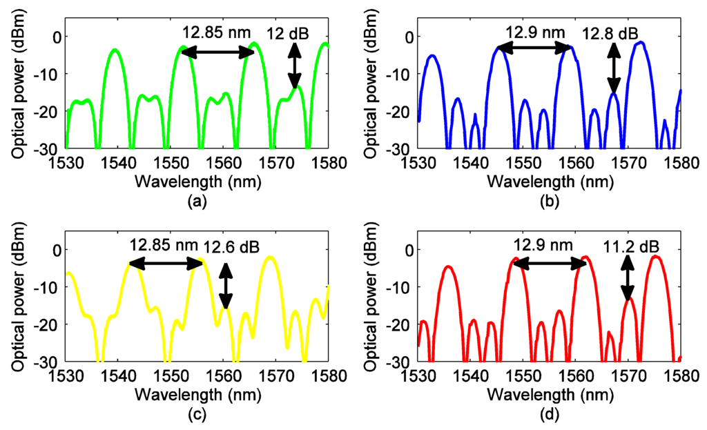
Figure 11.
Normalized transmission response of the four optical output channels (a) ch-1, (b) ch-2, (c) ch-3 and (d) ch-4.
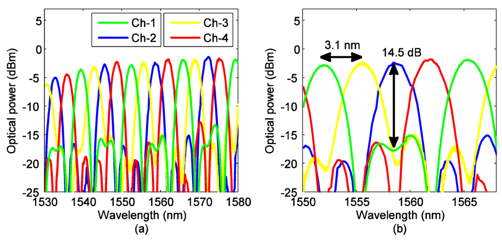
Figure 12.
(a) Overlapped transmission response of the four optical output channels. (b) Zoomed view of the optical response shows 14.5 dB crosstalk for ch-2.
3.3. 160 Gb/s Wavelength Division Multiplexing Operation
Figure 13 shows the experimental setup that was used to record the eye diagrams and to evaluate the BER performance of the four WDM channels. To demonstrate the WDM operation, four laser sources emitting continuous-wave (CW) light at wavelengths of 1552 nm, 1555.2 nm, 1558.4 nm and 1561.6 nm set with an optical power of 10 dBm/channel. The wavelengths of the CW signal were chosen such that they were aligned with the transmission power peaks of the four channel optical demultiplexer (Figure 12b).
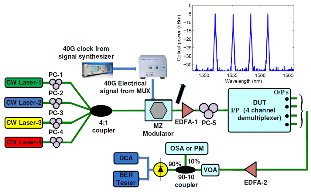
Figure 13.
Experimental setup to capture eye diagrams and to evaluate BER performance of the optical demultiplexer. EDFA: Erbium doped fiber amplifier, PM: power meter, OSA: Optical spectrum analyzer, DCA: digital communication analyzer. Inset shows the optical spectrum of the four modulated channels.
Polarization controllers (PC-1 to PC-4) were inserted at each of the CW channel paths to maximize the extinction ratio of the modulated signal from the polarization sensitive electro-optic LiNbO3 modulator. Prior to the external optical modulator, the four CW signals were multiplexed onto a single fiber using a 4:1 optical power coupler. The 4:1 optical power coupler has an insertion loss of around 6.4 dB. We measured around 9.5 dBm of total optical power from the output of the 4:1 optical coupler. The optically multiplexed four CW channels were given as input to the commercial LiNbO3 modulator. The modulator has a measured insertion loss of 7 dB. The optical modulator was driven by a 40 Gb/s non-return to zero (NRZ) on-off keying (OOK) electrical data generated from four 10 Gb/s pulse pattern generators (PPG). The four 10 Gb/s data generated from the PPGs were time multiplexed by the electrical multiplexer (MUX) to create the 40 Gb/s data. The electrical signal is a pseudorandom binary sequence (PRBS) data with a bit pattern of length 231 − 1.
To compensate for the insertion loss of the optical modulator and the device under test, two EDFAs (EDFA-1 and EDFA-2) with 5 dB noise figure were used before and after the chip. A polarization controller (PC-5) was used before the chip to control the polarization state of the input signal to the polarization sensitive Si3N4 waveguide. A variable optical attenuator (VOA) was used to control the received optical power by the commercial photodetector such that BER performance of the demultiplexer can be evaluated in terms of the average received power. A 90/10 optical coupler was used after the VOA to measure the amount of received power by the photodetector and to record the optical spectrum of the output signals. Figure 14 shows the recorded eye diagrams from the DCA for each of the four channels of the demultiplexer.
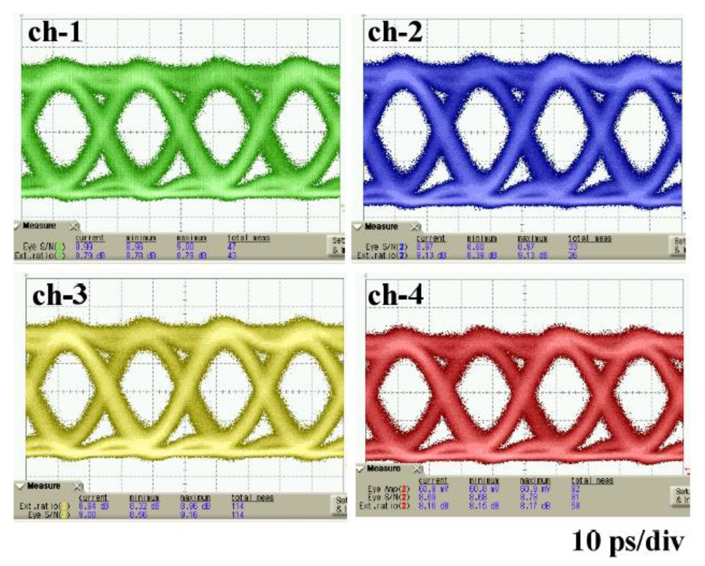
Figure 14.
40 Gb/s electrical eye diagrams obtained for the four channels at the output of the demultiplexer.
To measure the BER of all four channels, we used an electrical demultiplexer after the commercial photodetector to electronically demultiplex each of the 40 Gb/s channel to a 10 Gb/s channel. The 10 Gb/s data rate signal was used to measure the BER performance of each channel using a BER tester (Anritsu MU181040A-002). Figure 15 shows that an average received power of −2.5 dBm is required at the photodetector input to achieve 1 × 10⁻¹² BER for all four channels. It should be mentioned that the BER performance result does not include errors due to the crosstalk between channels, as all the channels were modulated with same PRBS data. In the case of the back-to-back link, only one CW signal source is modulated without using the 4:1 optical coupler, where the device under test is replaced by an optical attenuator set to the insertion loss of the Si3N4 demultiplexer (approximately 11.1 dB). The power penalty of 1 to 1.5 dB for ch-1 to ch-4 is attributed to the different optical gain setting in the two EDFA’s for the back-to-back case.
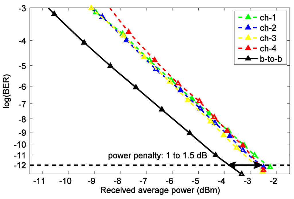
Figure 15.
Measured BER as a function of the average optical power at the input of the photodetector for the back-to-back and four output channels of the demultiplexer.
4. Conclusions
The performance results of the 1 × 4 channel optical demultiplexer circuit reported in this article suggests that complex optical signal processing functionalities can be added to the Si3N4 waveguide based components (i.e., phase shifting by thermal tuning, integrating optical buffers) such that more advantage from this ultra low-loss PIC technology can be harnessed. Using the integrated thermal tuners, the optical phase shift in the MZI delay arms can be controlled, which promises the scalability of the proposed demultiplexer architecture from four to eight channels by decreasing the adjacent channels’ separation. In this paper, we have designed the demultiplexer using 3.1 dB/m propagation loss Si3N4 waveguides with PECVD top cladding. However, by changing the waveguide cross-section of Si3N4 waveguides (50 nm × 6.5 µm) and by increasing the minimum bend radius to 9.8 mm with the PECVD top cladding, lower propagation losses (i.e., 0.5 dB/m in [9]) than a 3.1 dB/m loss are demonstrated. Therefore, in future designs, the losses of some application specific PICs (i.e., that includes long optical buffer waveguides with MZI based demultiplexers [1]) can be reduced by using the Si3N4 waveguides demonstrated in [9].
Acknowledgments
The chip was fabricated through LioniX BV and was supported by CMC Microsystems. This work was supported in part by the NSERC Discovery Grant Program and by the Canada Research Chairs Program.
The authors would like to thank Jessica Zhang, and Dan Deptuck, from CMC Microsystems, Kingston, ON, Canada, for their useful discussions.
Author Contributions
Mohammed Shafiqul Hai and Odile Liboiron-Ladouceur conceived and designed the experiments; Mohammed Shafiqul Hai performed the experiments; Mohammed Shafiqul Hai and Odile Liboiron-Ladouceur analyzed the data; Theo Veenstra, Arne Leinse, Odile Liboiron-Ladouceur contributed reagents/materials/analysis tools; Mohammed Shafiqul Hai wrote the paper.
Conflicts of Interest
The authors declare no conflict of interest.
References
- Liboiron-Ladouceur, O.; Raponi, P.G.; Andriolli, N.; Cerutti, I.; Hai, M.S.; Castoldi, P. A Scalable Space-Time Multi-plane Optical Interconnection Network Using Energy-Efficient Enabling Technologies. J. Opt. Commun. Netw. 2011, 3, A1–A11. [Google Scholar] [CrossRef]
- Lin, T.; Williams, K.A.; Penty, R.V.; White, I.H.; Glick, M. Capacity Scaling in a Multihost Wavelength-Striped SOA-Based Switch Fabric. J. Lightwave Technol. 2007, 25, 655–663. [Google Scholar] [CrossRef]
- Jinno, M.; Takara, H.; Sone, Y.; Yonenaga, K.; Hirano, A. Multiflow optical transponder for efficient multilayer optical networking. IEEE Commun. Mag. 2012, 50, 56–65. [Google Scholar] [CrossRef]
- Bauters, J.F.; Heck, M.J.R.; John, D.; Dai, D.; Tien, M.; Barton, J.S.; Leinse, A.; Heideman, R.G.; Blumenthal, D.J.; Bowers, J.E. Ultra-low-loss high-aspect-ratio Si3N4 waveguides. Opt. Express 2011, 19, 3163–3174. [Google Scholar] [CrossRef] [PubMed]
- Burmeister, E.F.; Mack, J.P.; Poulsen, H.N.; Mašanovic, M.L.; Stamenic, B.; Blumenthal, D.J.; Bowers, J.E. Photonic integrated circuit optical buffer for packet-switched networks. Opt. Express 2009, 17, 6629–6635. [Google Scholar] [CrossRef] [PubMed]
- Spencer, D.T.; Bauters, J.F.; Heck, M.J.R.; Bowers, J.E. Integrated waveguide coupled Si3N4 resonators in the ultrahigh-Q regime. Optica 2014, 1, 153–157. [Google Scholar] [CrossRef]
- Bauters, J.; Heck, M.; John, D.; Tien, M.-C.; Leinse, A.; Heideman, R.; Blumenthal, D.; Bowers, J. Ultra-low loss silica-based waveguides with millimeter bend radius. In Proceedings of the 36th European Conference on Optical Communication (ECOC), Torino, Italy, 19–23 September 2010.
- Chrostowski, L.; Hochberg, M. Silicon Photonics Design: From Devices to Systems; Cambridge University Press: Cambridge, UK, 2015. [Google Scholar]
- Bauters, J.F.; Heck, M.J.R.; John, D.D.; Barton, J.S.; Bruinink, C.M.; Leinse, A.; Heideman, R.G.; Blumenthal, D.J.; Bowers, J.E. Planar waveguides with less than 0.1 dB/m propagation loss fabricated with wafer bonding. Opt. Express 2011, 19, 24090–24101. [Google Scholar] [CrossRef] [PubMed]
- LeGrange, J.D.; Simsarian, J.E.; Bernasconi, P.; Buhl, L.; Gripp, J.; Neilson, D.T. Demonstration of an integrated buffer for an all-optical packet router. IEEE Photon. Technol. Lett. 2009, 21, 781–783. [Google Scholar] [CrossRef]
- Dai, D.; Wang, Z.; Bauters, J.F.; Tien, M.-C.; Heck, M.J.R.; Blumenthal, D.J.; Bowers, J.E. Low-loss Si3N4 arrayed-waveguide grating (de)multiplexer using nano-core optical waveguides. Opt. Express 2011, 19, 14130–14136. [Google Scholar] [CrossRef] [PubMed]
- Samadi, P.; Kostko, I.A.; Jain, A.; Shia, B.; Callender, C.L.; Dumais, P.; Jacob, S.; Chen, L.R. Tunable lattice-form Mach-Zehnder interferometer for arbitrary binary code generation at 40 GHz. IEEE J. Lightwave Technol. 2010, 28, 3070–3078. [Google Scholar] [CrossRef]
- Wörhoff, K.; Heideman, R.G.; Leinse, A.; Hoekman, M. TriPleX: A versatile dielectric photonic platform. Adv. Opt. Technol. 2015, 4, 189–207. [Google Scholar] [CrossRef]
- Thomson, D.J.; Hu, Y.; Reed, G.T.; Fedeli, J.-M. Low loss MMI couplers for high performance MZI modulators. IEEE Photon. Technol. Lett. 2010, 22, 1485–1487. [Google Scholar] [CrossRef]
- Madsen, C.K.; Zhao, J.H. Optical Filter Design and Analysis; Wiley: New York, NY, USA, 1999; pp. 171–177. [Google Scholar]
- Verbeek, B.H.; Henry, C.H.; Olsson, N.A.; Orlowsky, K.J.; Kazarinov, R.F.; Johnson, B.H. Integrated four-channel Mach-Zehnder multi/demultiplexer fabricated with phosphorous doped SiO2 waveguides on Si. J. Lightwave Technol. 1988, 6, 1011–1015. [Google Scholar] [CrossRef]
- Dulkeith, E.; Xia, F.; Schares, L.; Green, W.M.J.; Vlasov, Y.A. Group index and group velocity dispersion in silicon-on-insulator photonic wires. Opt. Express 2006, 14, 3853–3863. [Google Scholar] [CrossRef] [PubMed]
© 2015 by the authors; licensee MDPI, Basel, Switzerland. This article is an open access article distributed under the terms and conditions of the Creative Commons Attribution license (http://creativecommons.org/licenses/by/4.0/).