Article

Wavefront-Dependent Femtosecond Laser Processing of Battery Anodes Enabled by an SLM-Based Phase-Controlled Optical Setup


1
Laser Processing Research Laboratory, Department of Mechanical and Aerospace Engineering, University of Manchester, Manchester M13 9PL, UK
2
Cellerate Limited, Manchester M4 4BT, UK
*
Author to whom correspondence should be addressed.
Photonics 2026, 13(7), 663; https://doi.org/10.3390/photonics13070663
Submission received: 3 June 2026 / Revised: 2 July 2026 / Accepted: 9 July 2026 / Published: 11 July 2026
(This article belongs to the Special Issue Advanced Techniques for Laser Processing)

Abstract

This study presents a phase-characterised optical set-up for shaped-beam femtosecond laser processing of double-sided lithium-ion battery anodes. The phase response was found to be power-independent, with consistent phase scaling across applied powers and a 2 π phase shift completed at approximately 220–225 grey levels (GL). The measured modulation visibility stayed high. The generated beam profiles were in good agreement with MATLAB simulations, confirming reliable wavefront control. Under identical processing conditions, wavefronts carrying different orbital angular momentum (OAM) produced distinct kerf morphologies: at 30 overscans, m = 0 gave a deeper cut with a taper angle of 16.5 ± 1.1 ° , while m = 1 gave a shallower groove with a less steep angle of 26.3 ± 1.9 ° , indicating different Cu-layer interaction and ejecta behaviour. When the overscan number was increased to 45 at the same average power, both m = 0 and m = 1 achieved through-cuts. However, the m = 1 condition produced a cleaner cut edge, a more vertical kerf wall, and reduced graphite delamination and heat-affected damage compared with the Gaussian beam. These results demonstrate the potential of wavefront engineering for laser processing of layered battery anodes, where improved cut confinement and edge quality can be achieved through beam shaping under relatively low-energy, moderate-overscan, and tight-focusing conditions.

1. Introduction

Lithium-ion batteries (LIBs) are rechargeable energy storage devices extensively utilised in electric vehicles, portable electronics, stationary energy storage systems, and household appliances [1,2,3,4]. Their widespread adoption in various fields is primarily driven by their high energy density, low self-discharge rate, and favourable energy-to-weight ratio, alongside the ability to be recycled, thus retaining their economic value and supporting sustainable development [2,3]. The conventional manufacturing process of LIBs generally involves three principal stages: electrode production, cell assembly, and electrochemical formation, incorporating techniques such as mechanical rolling and calendering for layered electrode sheet production and punching for the required anode or cathode size and shape [4]. Electrode fabrication is particularly crucial as it directly influences material utilisation, manufacturing costs, and the overall performance of the final cell. Studies have shown that the failure rate, including short-circuiting and below manufacturing standards, of mechanically manufactured whole cells could reach as high as 30% due to local electrode coating detachment around the punched edge in conjunction with pre-existing tearing or cracking caused by the calendaring process [5,6]. Thus, the fabrication of LIB electrodes should prioritise the minimisation of defects and material waste to ensure the whole-cell’s overall durability and performance.
Laser material processing (LMP) has developed into an efficient, flexible, and non-contact manufacturing approach, and is now widely applied in the precision processing of thin films and multilayer materials [2,3,4,7,8,9]. In LIB manufacturing, laser-based methods have been explored for applications including drying or activation of functional materials, electrode cutting, and selective surface processing of thin-film or layered structures, where controlled material removal is required without damaging the underlying layers. Laser-induced surface structuring has also shown potential for improving charge transport and ion transport, thereby contributing to enhanced whole-cell performance [9]. Compared with continuous-wave or long-pulse-width lasers, short-pulsed laser processing offers several advantages, including reduced thermal impact on substrate material of a layered structure, a smaller heat-affected zone (HAZ), and the potential for higher processing speed and industrial throughput [2,3,4,7,8,9,10,11,12].
Among LIB components, graphite/Cu/graphite anodes present a particularly challenging processing case because the multilayer architecture requires controlled cutting through all constituent layers, while limiting thermal and mechanical damage to the surrounding edge region and minimising defects such as Cu redeposition and graphite delamination. Beam-shaping techniques can further optimise laser–material interactions. Recent high-power beam-shaping work, using a phase-only spatial light modulator (SLM) at powers up to 383 W, has also demonstrated not only stable phase modulation over a defined power range with a first-order diffraction efficiency of 0.98 ± 0.01 at 300 W, but also good multi-beam processing consistency, with five-spot drilling uniformity of 0.72 ± 0.04 over the 200–300 W range [10]. Wavefront control through an SLM also enables the generation of tailored wavefront intensity distributions, offering greater flexibility than a conventional Gaussian beam. Recent studies have shown that shaped ultrafast beams with different orbital angular momentum (OAM) can achieve high-precision, single-step, full-depth cutting of 200 μm-thick silicon sheets with a sidewall roughness as low as 191 nm Ra, demonstrating the potential of wavefront-engineered laser processing to improve cut quality and kerf-edge straightness [8].
From an industrial perspective, battery electrode singulation requires not only sufficient cutting efficiency but also robust control of edge quality, delamination, redeposition, and thermal damage [4,5,6]. Previous studies have shown that cutting-edge characteristics can measurably affect electrochemical performance. Jansen et al. [13] reported that laser-generated cutting-edge features, particularly cathode-edge contamination by metal spatters, influenced the cycle stability of large-format pouch cells. Li et al. [14] also showed that the taper angle of femtosecond-laser-cut electrodes could strongly affect rate capability and cycling performance. These factors are directly relevant to downstream cell assembly, handling reliability, and electrochemical consistency [6]. In this context, wavefront engineering is of interest because it offers a means of tailoring the laser–material interaction without necessarily increasing the nominal energy input and may therefore provide a practical route towards more controlled laser-based electrode processing [7,8,9,10,15,16,17]. Thus, this study aims to investigate the phase linearity of an SLM-based optical setup and examine how different beam wavefronts influence cutting behaviour in a double-sided graphite/Cu/graphite battery anode structure. The investigation also demonstrates that wavefront-dependent laser–material interaction can produce distinct kerf morphologies and Cu-layer responses in this multilayer architecture, showing that shaped wavefronts can improve kerf-edge and processing qualities relative to the Gaussian beam under the same nominal processing conditions.

2. Experimental Methods

2.1. Optical Setup and Laser-Processing Procedure

The material investigated in this study was a commercial lithium-ion battery anode supplied by Cellerate Ltd. (Manchester, UK)The anode had an overall thickness of approximately 130 μ m and comprised graphite active material coated on both sides of a copper current collector. The graphite coating thickness was approximately 60 μ m on each side, while the copper foil thickness was approximately 10 μ m.
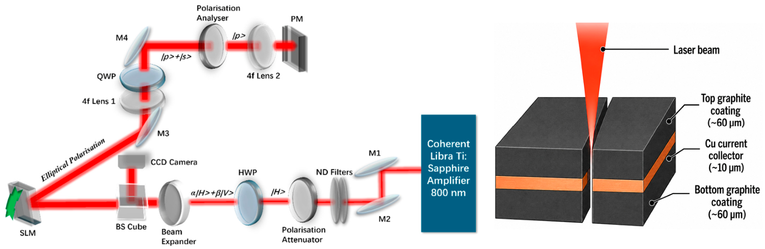
The experimental setup used for shaped-beam femtosecond laser processing is shown in Figure 1. The laser source was a Ti:sapphire femtosecond amplifier system (Coherent Libra, Coherent Inc., Santa Clara, CA, USA), operating at a central wavelength of 800 nm, with a pulse duration of 100 fs, repetition rate of 1 kHz, and beam quality factor M 2 < 1.5 . The output beam was collimated at the source and set to a horizontally linearly polarised state using the polarisation attenuator, followed by a telescope and a beam-splitting (BS) cube. The BS cube directed part of the beam to a camera for monitoring the beam profile and quality before projection onto the Hamamatsu (Shizuoka, Japan) LCOS spatial light modulator (LCOS-SLM X10468). Phase modulation was controlled using computer-generated holograms (CGHs) to generate the required wavefront. Optical power was recorded using a Gentec-EO (Quebec City, QC, Canada) power meter with a Thorlabs sensor head, where 100 counts were collected for each measurement, with an overall uncertainty of ±3%. The power meter showed a background noise level of approximately 0.3 Mw. Beam profiling was carried out under the same arrangement by replacing the power meter with a Thorlabs (Newton, NJ, USA) beam profiling camera (BC106N-VIS/M).
For anode processing, the beam diffracted from the SLM was relayed through the same downstream 4f optical system with a measured D 4 σ beam width of approximately 5 mm prior to focusing. By replacing the power meter or profiler, the beam was focused onto the sample using an OLYMPUS (Tokyo, Japan) MPLan Nx50 objective lens with a numerical aperture of 0.75 and a focal length of 3.6 mm. This high-numerical-aperture arrangement resulted in a focal spot diameter of around 1.1 μm and a depth of field of 1.6 μm, enabling strong beam confinement and highly localised interaction with the multilayer anode structure. Laser cutting experiments were performed using beams carrying different OAM states (m = 0, 1, 3 and 4) directly using the built-in function of the SLM, in order to examine the influence of the wavefront on the cutting response. To isolate the effect of wavefront variation, all other processing parameters were kept constant throughout the experiments. The overscan number was fixed at 30 and 45, the applied power was maintained at approximately 19 mW, and the scanning speed was set to 1 mm/s. Finally, a white light interferometer (Polytec GmbH TMS-A-MVS-01, Baden-Württemberg, Germany) was employed to analyse the cut features and kerf profiling, whereas a Keyence (Osaka, Japan) VHX-X1 digital microscope was used to acquire stacked depth-resolved images for further morphological validations and LIBS elemental analysis. For each processing condition, kerf morphology was quantified from one representative edge of a square cut. Kerf width, maximum depth, taper angle, and delamination size were measured at three positions along this edge using interferometry and optical microscopy. The reported values are given as the mean ± standard deviation of these three measurements. The remaining three edges were also examined for qualitative consistency in cut morphology. No post-processing or cleaning treatment was applied after laser cutting.

2.2. Phase Measurement

The phase shift introduced by the SLM was characterised by measuring the output optical power as a function of the applied grey level (GL). The incident beam was conditioned using the polarisation optics described in Section 2.1, such that the phase shift imposed by the SLM could be converted into an intensity variation at the power detector. The measured optical power was fitted using a sinusoidal model of the form [11]
I ( G L ) = A s i n 2 ( a G L + b ) + C
where I is the measured optical power, A represents the modulation amplitude, C is the background offset, and a and b correspond to the phase scaling factor and phase offset, respectively. From this fit, the phase shift induced by the SLM was obtained as
ϕ ( G L ) = 2 ( a G L + b )
Following the sinusoidal dependence of the measured intensity on the optical phase shift. For normalised representation, the phase shift was further expressed in units of π as
ϕ π ( G L ) = 2 a π G L
where the offset term b was neglected, since only the relative phase variation was required for comparison. Using this mapping, the measured power response was re-expressed as a function of phase shift, thereby enabling direct comparison of the SLM phase response across different input powers, highlighting the stability and consistency of phase-only modulation.

3. Result and Discussion

3.1. Phase Response and Beam Characterisation

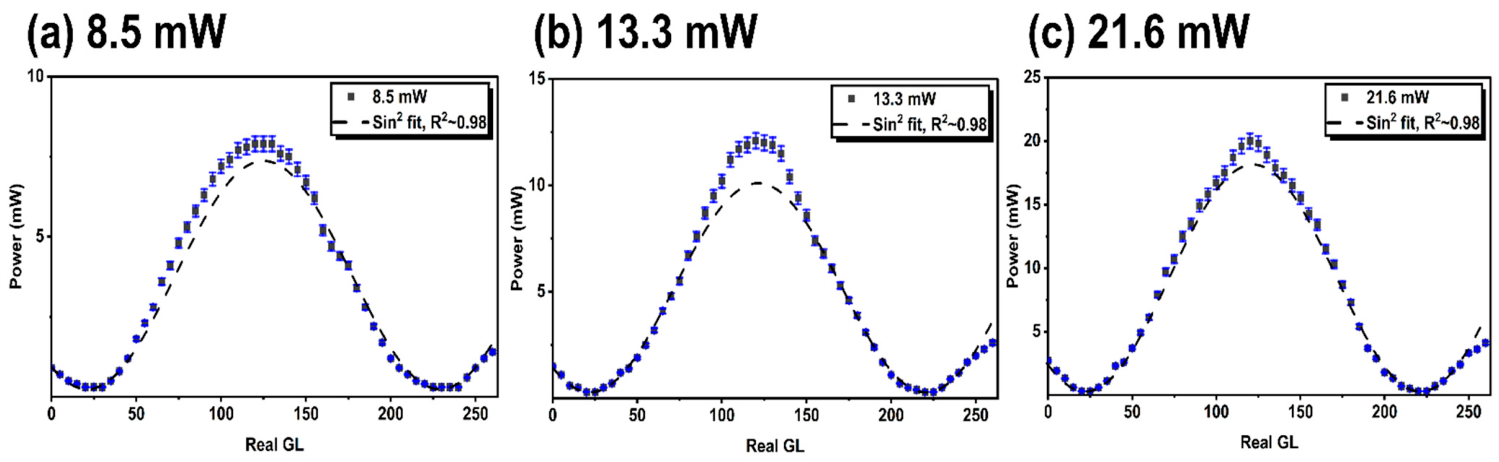
For phase-response measurements, the HWP was positioned before the telescope and set at 22.5 ° , thereby rotating the incident linear polarisation by 45 ° prior to reflection from the SLM. Owing to the GL-dependent phase shift introduced by the SLM when the incident polarisation was oriented away from its fast axis, the reflected beam became elliptically polarised. This elliptically polarised beam was then converted back into a rotated linear state using a QWP set at 45 ° , positioned upstream of the 4f relay system. A rotational polarisation analyser, also set at 45 ° , was subsequently used to transmit the | p component of the beam to the power meter, while the orthogonal component was blocked. The SLM blazing function was set to 255:255, meaning that no pre-calibration was applied to the addressed GLs. Consequently, a GL value of 255 corresponded to the maximum phase shift achievable by the device, rather than to a predefined 2 π phase shift, thereby enabling the full phase-response range of the modulator to be examined. The measured responses, represented by the transmitted power through the polarisation analyser against the applied grey level, are shown in Figure 2a–c.
The transmitted power data were fitted using the function I t r a n s ( ϕ ) = A s i n 2 ( a G L + b ) + C , corresponding to an approximately linear phase response with a modulation visibility, defined as ( I m a x I m i n ) / ( I m a x + I m i n ) , lower than unity. The applied GLs were converted to phase shift ϕ in radians, with the value 2 π assigned when the measured transmitted power returned to its initial level at GL = 0. Using this calibration, the required range for a full 2 π phase shift remained approximately constant at Δ ( G L ) 2 π = 220 225 for 8.5, 13.3, and 21.6 mW, respectively. The extracted phase scaling factors from I t r a n s ϕ function were α = 0.0149, 0.0159, and 0.0155 for the applied incident powers, indicating consistent phase scaling with less than 3% variation across the investigated power range. This confirms that the phase response was effectively independent of incident optical power under the present conditions. In addition, the calculated modulation visibility remained high at approximately 0.93–0.97 for all three powers. The small deviation from unity is attributed mainly to detector noise, which becomes more significant at lower tested power.

3.2. OAM-Dependent Anode Cutting

By applying CGHs on the SLM with an azimuthal phase term, different ring modes with various helical wavefronts were generated for m = 1, 3, and 4, each carrying the corresponding orbital angular momentum.
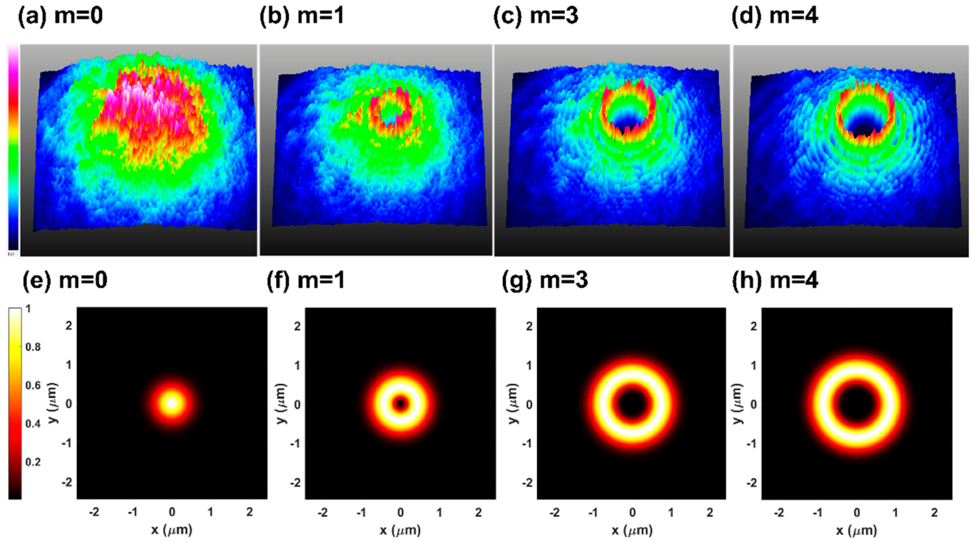
For a Laguerre–Gaussian-type ring mode, the expected transverse intensity distribution is given by I ( r ) = I 0 2 m m ! r 2 ω 0 2 m e x p ( 2 r 2 ω 0 2 ) , where I 0 is the peak intensity of the initial Gaussian beam and ω 0 is its 1 / e 2 radius [12]. If no OAM is applied (m = 0), the beam is Gaussian-distributed and acts as a reference. The radius at which the ring intensity reaches its maximum is R m a x = m 2 ω 0 , hence the corresponding peak ring intensity is I p e a k = I 0 m m m ! e m . Therefore, the ring peak reaches approximately 36.8%, 22.4%, and 19.5% of the initial Gaussian peak intensity for m = 1, 3, and 4, respectively. Figure 3a–h shows the expected 2D intensity cross-sections for these modes. The calculated 3D ring-beam intensity distributions obtained in MATLAB (v.2025b) were in good agreement with the beam profiles captured experimentally using the beam profiler, confirming reliable generation of the required wavefronts from the SLM.
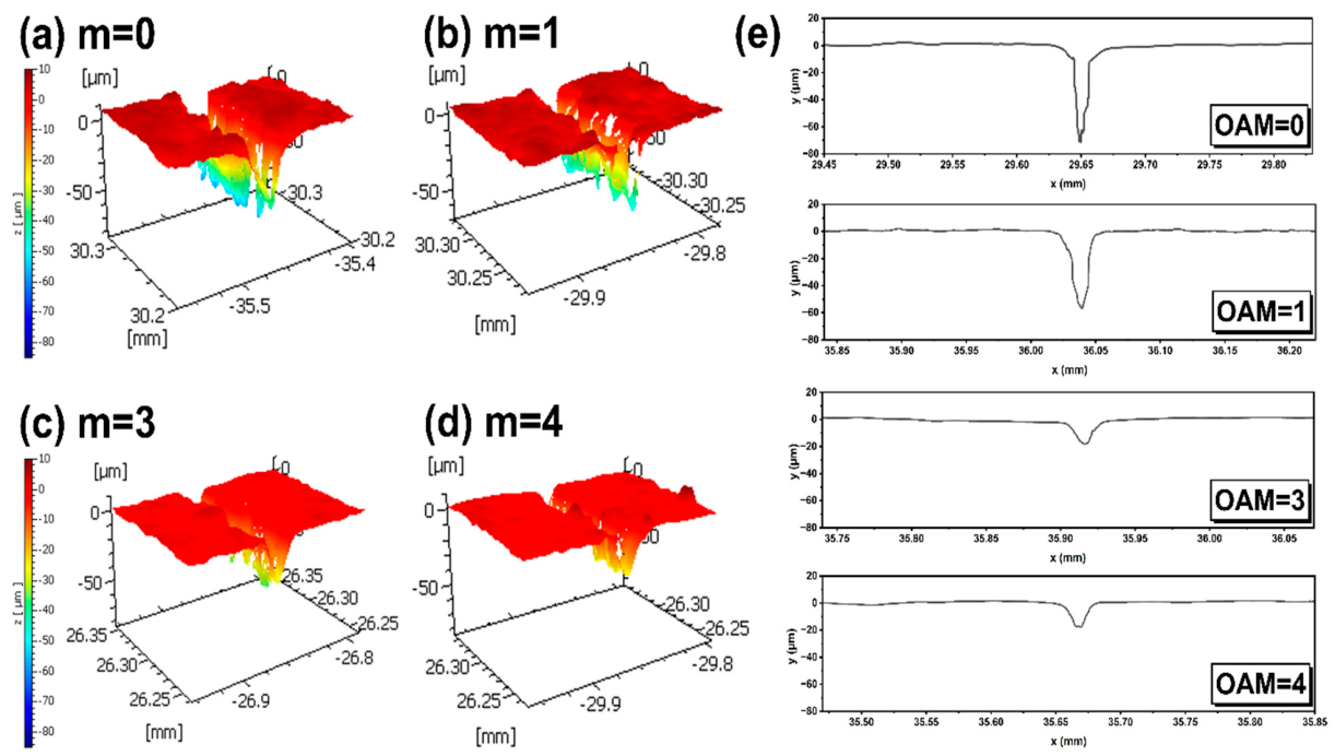
Laser cutting was carried out at 30 overscans, 19 mW average power, and a scanning speed of 1 mm/s for all applied orbital angular momentum states. Distinct wavefront-dependent cutting behaviour was observed in Figure 4a–e. For m = 0 and m = 1 , relatively narrow kerfs were produced, with measured openings of 22.3 ± 1.1 and 17.6 ± 0.9 μ m, and maximum depths of 70.2 ± 4.9 and 60.1 ± 4.2 μ m, respectively. Under these conditions, the upper graphite layer was fully removed in both cases. For m = 0 , the Gaussian beam penetrated through the Cu current collector and into the lower graphite layer. In contrast, for m = 1 , the cut reached the Cu layer without removing the Cu layer as extensively as the Gaussian beam, as seen in Figure 4e. At higher orbital angular momentum states of m = 3 and 4, the further outward redistribution of energy reduced the central energy density below that required for effective deep penetration, thereby limiting removal largely to the near-surface region. This behaviour is consistent with the redistribution of the beam energy into a ring-shaped intensity profile as the orbital angular momentum increases.
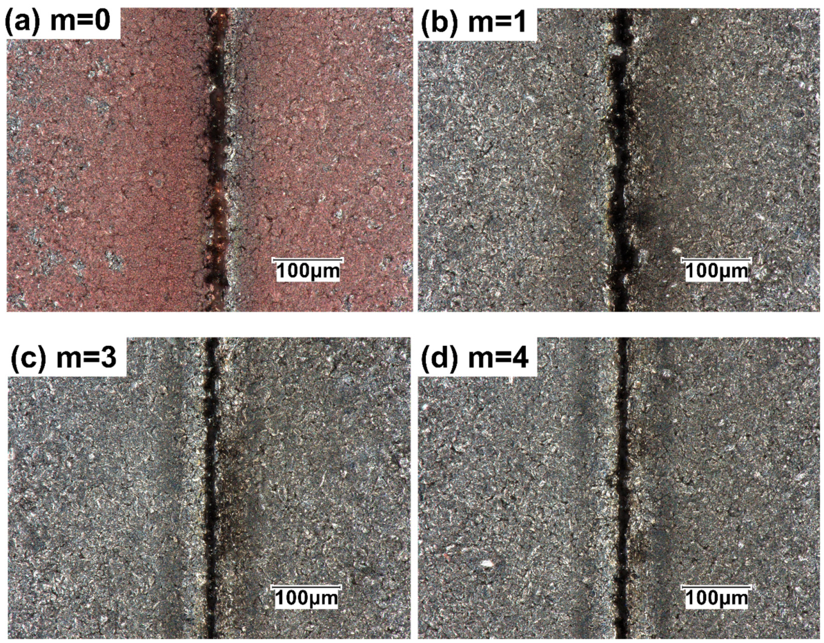
In particular, for m = 1 , the peak intensity is reduced to approximately 36.8% of that of the Gaussian beam with the same total energy. Despite this substantial reduction in peak intensity, the beam still produced a relatively deep cut, suggesting that material removal was not governed by peak intensity alone [10]. Instead, the modified spatial distribution of energy likely altered the local absorption, heat accumulation, and ablation front development within the graphite layer [8,10]. Compared with the Gaussian beam, the m = 1 mode distributed energy over a wider annular region at approximately 1.41 times the focal spot area, which may have reduced excessive localised penetration while still maintaining sufficient fluence for substantial graphite removal. This indicates that wavefront shaping can influence not only penetration depth, but also the way the multilayer structure is engaged. Figure 5a–d shows the difference in cut surface morphology.
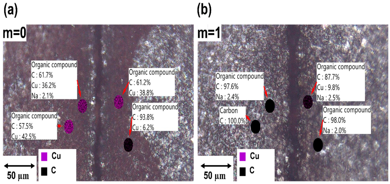
For m = 0 , the cut is accompanied by clear Cu redeposition surrounding the kerf opening, visible as a colour change from the original graphite. In contrast, although the m = 1 condition partially removed the Cu layer, the extent of Cu redeposition was visibly less pronounced. This difference is consistent with the distinct kerf geometries obtained under the two wavefront conditions. The groove produced at m = 0 exhibited a taper angle of 16.5 ± 1.1 ° , whereas the groove generated at m = 1 showed a less steep taper angle of 26.3 ± 1.9 ° , with taper defined as the half-angle relative to the vertical axis of the groove. The narrow and tapered cut geometry obtained at m = 0 is likely to have increased confinement of Cu-containing ejecta, thereby promoting local redeposition around the kerf opening [8,15]. LIBS elemental analysis in Figure 6 further supports this interpretation, showing a high Cu concentration around the cut region for m = 0 , whereas for m = 1 , only a minor Cu wt% was detected at the measurement point closest to the kerf.
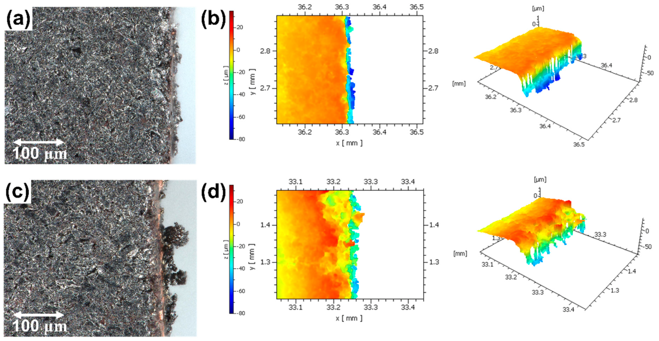
At a higher overscan number of 45, while maintaining an average power of 19 mW and the same scanning speed, both m = 0 and m = 1 produced through-cuts in the multilayer anode, as shown in Figure 7. The energy delivered during processing was quantified as the energy per unit length, E line = P / v , where P is the average power and v is the scanning speed. For P = 19 mW and v = 1   m m   s 1 , E line = 0.019   J   m m 1 . With 45 passes, the accumulated energy reached 0.855 J   m m 1 . As these parameters were identical for both the Gaussian beam and the vortex beam ( m = 1 ), the total deposited energy per unit length was conserved. Despite this, the cut morphology differed clearly. For m = 0 , delamination around the kerf was more obvious, with approximately 18.9 ±   1.7   μ m of top-graphite delamination from the Cu mid-layer, as shown in Figure 7c,d. The cut’s sidewall appeared more inclined through the anode thickness. In contrast, under the same nominal energy deposition conditions, the vortex beam with m = 1 produced a cleaner kerf opening, with almost no visible top-graphite delamination from the Cu layer. The m = 1 cut’s sidewall also appeared more vertical (Figure 7a,b), indicating a more confined penetration path through the multilayer structure. The HAZ was also visually and morphologically reduced compared with the Gaussian-processed cut.
The difference in cut results can be understood from the spatial redistribution of energy introduced by wavefront shaping. For a focused diameter of 1.1 μm ( w = 0.55 μm), the Gaussian beam area is A 0 = π w 2 0.95 × 10 8 cm2, giving an effective energy density of 2.0 × 10 3 J/cm2. For the vortex beam, the annular intensity profile was approximated by an effective area of A m = 1 2 π w 2 1.34 × 10 8 cm2, giving 1.4 × 10 3 J/cm2, or about 70% of the Gaussian case [12]. The corresponding peak intensity is reduced to about 36.8% of the Gaussian value. Thus, although the total deposited energy remained unchanged, beam shaping redistributed this energy over a larger effective interaction area, lowering both the peak intensity and the local energy density.
The role of this redistribution is likely twofold. First, the reduced peak intensity may have limited excessive local penetration, which moderated the interaction with the Cu current collector, thereby reducing severe local damage and remelting. Second, the annular energy deposition of the m = 1 beam is likely to have altered the way the kerf developed through the multilayer structure, promoting a wider cut path rather than the narrower and more tapered morphology obtained with the Gaussian beam. This difference in kerf evolution is important because the final cut morphology should not be attributed to energy density alone.
A further consequence is likely related to ejecta transport. For the Gaussian beam, the narrower and more tapered groove may have increased confinement of Cu-containing ejecta and promoted collision with the upper kerf rims, thereby increasing local redeposition. In contrast, the wider U-shaped geometry associated with the m = 1 condition may have facilitated ejecta escape from deeper regions and reduced interaction with the top rims. This would be consistent with the lower apparent Cu redeposition, and improved kerf-edge quality observed under the m = 1 condition.
Graphite delamination is also likely influenced by the wavefront-dependent spatial distribution of energy and the resulting interactions at the graphite/Cu interface. In the m = 1 condition, the annular beam deposits energy around the kerf perimeter rather than concentrating it at the centre of the spot. Once the top graphite layer is penetrated, this ring-like energy distribution is likely to modify how the Cu current collector is engaged, promoting a more distributed interaction around the cut boundary instead of a highly localised central ablation as in the Gaussian case. Such a difference may promote a wider escape path for Cu-containing ejecta, reduce local redeposition near the kerf rim, and lessen interfacial damage at the graphite/Cu boundary. This may help explain why the m = 1 condition produced a cleaner cut edge with reduced delamination. This difference in cut development may alter how the graphite/Cu interface engages and therefore influence the tendency for top-graphite delamination [15,16,17]. Under the present low-energy, moderate-overscan, and tight-focusing conditions, the shaped beam therefore appears to favour more spatially confined penetration with reduced interfacial damage, which may explain why comparable through-cutting could still be achieved while reducing delamination for m = 1 [1,8,10,17]. From this perspective, the m = 1 wavefront does not merely reduce the effective cutting intensity but modifies the laser–material interaction through a combined change in peak intensity, spatial energy deposition, kerf evolution, ejecta transport, and interface engagement [1,8].
From an industrial processing viewpoint, the improved cut-edge quality observed under the m = 1 condition is significant because edge delamination, redeposition, and thermal damage are all undesirable in electrode singulation [6,13,14,18]. The present results suggest that beam shaping may provide an additional process-control parameter for quality-driven optimisation, allowing the kerf morphology to be tuned under the same nominal line-energy condition. This may be particularly valuable when combined with tightly focused ultrafast processing conditions, where localised energy delivery and repeated moderate-pass exposure can support high edge quality. Although the current work was not designed as a throughput study, the findings indicate potential for extending wavefront-engineered ultrafast processing towards more robust and application-relevant electrode cutting.

4. Conclusions

A phase-characterised optical set-up for shaped-beam femtosecond laser processing of double-sided battery anodes was demonstrated. The SLM showed a stable and power-independent phase response, enabling reliable wavefront control. Under identical processing conditions, different orbital angular momentum states produced clear differences in kerf geometry and Cu-layer interaction. At 30 overscans, the Gaussian beam ( m = 0 ) achieved the deepest penetration of around 70 μ m, but it also promoted strong Cu redeposition. The shaped m = 1 beam reduced apparent redeposition and produced a less steep kerf taper. At 45 overscans, both m = 0 and m = 1 produced through-cuts in the layered anode, but the m = 1 condition gave a cleaner edge, a more vertical kerf wall, and less graphite delamination. These results show that wavefront engineering can control both penetration behaviour and cut quality in multilayer battery anodes. This was demonstrated under relatively low-energy, moderate-overscan, and tight-focusing conditions, where beam shaping still enabled improved cut confinement and edge quality. This is particularly relevant to future industrial battery manufacturing, where improved control of cutting-edge quality and defect formation is essential for reliable electrode singulation and consistent cell performance. Future work will explore a higher-throughput process using a high-power SLM and compare the electrochemical performance of electrodes cut under different wavefront conditions.

Author Contributions

Conceptualization, O.A. and S.Z.; methodology, O.A. and S.Z.; software, S.Z. and Y.W.; validation, O.A., S.Z. and Y.W.; formal analysis, S.Z.; investigation, S.Z.; resources, R.F.; data curation, S.Z. and Y.W.; writing—original draft preparation, S.Z.; writing—review and editing, O.A., Y.W. and R.F.; visualization, S.Z., O.A. and Y.W.; supervision, O.A. and R.F.; project administration, O.A. and R.F. All authors have read and agreed to the published version of the manuscript.

Funding

This research received no external funding.

Institutional Review Board Statement

Not applicable.

Informed Consent Statement

Not applicable.

Data Availability Statement

Data are contained within the article.

Acknowledgments

We would like to thank Cellerate Ltd. for providing the materials used in this study.

Conflicts of Interest

Author Richard Fields is employed by Cellerate Limited. The remaining authors certify that no commercial, personal, or professional relationships influenced the research design, data interpretation, or conclusions of this study.

References

  1. Degen, F. Lithium-ion battery cell production in Europe: Scenarios for reducing energy consumption and greenhouse gas emissions until 2030. J. Ind. Ecol. 2023, 27, 964–976. [Google Scholar] [CrossRef]
  2. Berhe, M.; Oh, H.; Park, S.; Lee, D. Laser cutting of silicon anode for lithium-ion batteries. J. Mater. Res. Technol. 2022, 16, 322–334. [Google Scholar] [CrossRef]
  3. Orojloo, P.; Demir, A. Study of burst mode for enhancing the ps-laser cutting performance of lithium-ion battery electrodes. J. Laser Appl. 2024, 36, 042013. [Google Scholar] [CrossRef]
  4. Liu, Y.; Zhang, R.; Wang, J.; Wang, Y. Current and future lithium-ion battery manufacturing. iScience 2021, 24, 102332. [Google Scholar] [CrossRef] [PubMed]
  5. Gaines, L.; Dai, Q.; Vaughey, J.; Gillard, S. Direct Recycling R&D at the ReCell Centre. Recycling 2021, 6, 31. [Google Scholar] [CrossRef]
  6. Limé, A.; Lein, T.; Maletti, S.; Schmal, K.; Reuber, S.; Heubner, C.; Michaelis, A. Impact of Electrode Defects on Battery Cell Performance: A Review. Batter. Supercaps 2022, 5, e202200239. [Google Scholar] [CrossRef]
  7. Zuo, S.; Pulham, C.; Spooner, E.; Crowe, I.; Kılıç, Z.; Allegre, O. Picosecond laser processing of ITO and AZO thin films: The impact of substrate material and multi-pulse incubation on ablation thresholds. Opt. Express 2025, 33, 43599–43616. [Google Scholar] [CrossRef] [PubMed]
  8. Li, Z.; Allegre, O.; Li, Q.; Guo, W.; Li, L. Femtosecond laser single step, full depth cutting of thick silicon sheets with low surface roughness. Opt. Laser Technol. 2021, 138, 106899. [Google Scholar] [CrossRef]
  9. Kriegler, J.; Ballmes, H.; Dib, S.; Demir, A.; Hille, L.; Liang, Y.; Wach, L.; Weinmann, S.; Keilhofer, J.; Kim, K.J.; et al. Surface Reconditioning of Lithium Metal Electrodes by Laser Treatment for the Industrial Production of Enhanced Lithium Metal Batteries. Adv. Funct. Mater. 2024, 34, 2313766. [Google Scholar] [CrossRef]
  10. Zuo, S.; Wang, S.; Pulham, C.; Tang, Y.; Perrie, W.; Allegre, O.; Tang, Y.; Sharp, M.; Leach, J.; Whitehead, D.J.; et al. High-Performance NIR Laser-Beam Shaping and Materials Processing at 350 W with a Spatial Light Modulator. Photonics 2025, 12, 544. [Google Scholar] [CrossRef]
  11. Yeh, P. Optics of Liquid Crystal Displays. In Proceedings of the Conference on Lasers and Electro-Optics/Pacific Rim; Paper ME2_1; Optica Publishing Group: Washington, DC, USA, 2007. [Google Scholar]
  12. Shen, Y.; Zhan, Q.; Wright, L.; Christodoulides, D.; Wise, F.; Willner, A.; Zou, K.-H.; Zhao, Z.; Porras, M.A.; Chong, A.; et al. Roadmap on spatiotemporal light fields. J. Opt. 2023, 25, 09300. [Google Scholar] [CrossRef]
  13. Jansen, T.; Kandula, M.; Hartwig, S.; Hoffmann, L.; Haselrieder, W.; Dilger, K. Influence of Laser-Generated Cutting Edges on the Electrical Performance of Large Lithium-Ion Pouch Cells. Batteries 2019, 5, 73. [Google Scholar] [CrossRef]
  14. Li, Q.; Sun, X.; Mei, X.; Wang, L.; Wang, W.; Cui, J. High-quality femtosecond laser cutting of battery electrodes with enhanced electrochemical performance by regulating the taper angle: Promoting green manufacturing and chemistry. Appl. Energy 2025, 377, 124452. [Google Scholar] [CrossRef]
  15. Zhou, T.; Kraft, S.; Perrie, W.; Schille, J.; Loeschner, U.; Edwardson, S.; Dearden, G. Backward Flux Re-Deposition Patterns during Multi-Spot Laser Ablation of Stainless Steel with Picosecond and Femtosecond Pulses in Air. Materials 2021, 14, 2243. [Google Scholar] [CrossRef] [PubMed]
  16. Schmidt, M.; Cvecek, K.; Duflou, J.R.; Vollertsen, F.; Arnold, C.B.; Matthews, M.J. Dynamic beam shaping—Improving laser materials processing via feature synchronous energy coupling. CIRP Ann. 2024, 73, 533–559. [Google Scholar] [CrossRef]
  17. Lind, J.; Hagenlocher, C.; Weckenmann, N.; Blázquez-Sánchez, D.; Weber, R.; Graf, T. Adjustment of the geometries of the cutting front and the kerf by means of beam shaping to maximize the speed of laser cutting. Int. J. Adv. Manuf. Technol. 2023, 126, 1527–1538. [Google Scholar] [CrossRef]
  18. Ravesio, E.; Montinaro, G.; Mincuzzi, G.; Negozio, M.; Versaci, D.; Gartiser, V.; Lutey, A.H.A.; Bella, F.; Bodoardo, S. Ultrashort pulsed laser texturing of current collector for Si/C Li-ion anodes: Characterisation of electrochemical performance and evolution of interface morphology. J. Energy Storage 2025, 109, 115226. [Google Scholar] [CrossRef]
Figure 1. Schematic of the experimental set-up for phase-response measurements using the SLM and the structural layout of the anode laser processing. During processing, the HWP was set to 0 ° , and the QWP and polarisation analyser were removed. The power meter was replaced with a high-NA objective lens for sample processing. The sample was positioned on an Aerotech translation stage, which controls X-Y-Z motion.
Photonics 13 00663 g001
Figure 2. Measured responses of the SLM with increasing power at (a) 8.5 mW, (b) 13.3 mW and (c) 21.6 mW. The Sin2 fits (dashed lines) are in excellent agreement with the measured response, showing R2 values of around 0.98. Error bars represent the standard deviation estimated from the internal measurement uncertainty of the power meter.
Photonics 13 00663 g002
Figure 3. Comparison of experimentally measured beam profiles where colour codes represent normalised intensity (ad) and MATLAB-simulated intensity distributions (eh) for m = 0, 1, 3, and 4.
Photonics 13 00663 g003
Figure 4. 3D surface (ad) and cross-sectional line profiles (e) of laser-cut kerfs on double-sided graphite anode produced with different OAM states.
Photonics 13 00663 g004
Figure 5. Optical images showing wavefront-dependent surface morphology and Cu redeposition behaviour in laser-cut anodes at (a) m = 0, (b) m = 1, (c) m = 3 and (d) m = 4.
Photonics 13 00663 g005
Figure 6. LIBS elemental analysis of Cu concentration (wt%) around the laser-cut region for (a) m = 0 and (b) m = 1 .
Photonics 13 00663 g006
Figure 7. Optical microscopy and interferometry images of through-cut morphologies on double-sided battery anodes processed with (a,b) m = 1 and (c,d) m = 0 .
Photonics 13 00663 g007
Disclaimer/Publisher’s Note: The statements, opinions and data contained in all publications are solely those of the individual author(s) and contributor(s) and not of MDPI and/or the editor(s). MDPI and/or the editor(s) disclaim responsibility for any injury to people or property resulting from any ideas, methods, instructions or products referred to in the content.