Article

Analysis and Design of High-Efficiency Resonant Beam Charging and Communication


1
College of Electronics and Information Engineering, Tongji University, Shanghai 201804, China
2
Shanghai Aerospace Electronics Co., Ltd., Shanghai 201821, China
3
School of Computer Science and Technology, Tongji University, Shanghai 201804, China
4
College of Transportation, Tongji University, Shanghai 201804, China
5
Key Laboratory for Information Science of Electromagnetic Waves, Department of Communication Science and Engineering, Fudan University, Shanghai 200433, China
*
Author to whom correspondence should be addressed.
Photonics 2026, 13(7), 659; https://doi.org/10.3390/photonics13070659
Submission received: 27 May 2026 / Revised: 2 July 2026 / Accepted: 3 July 2026 / Published: 9 July 2026

Abstract

With the development of the Internet of Things (IoT), demands of power and data for IoT devices increase drastically. In order to resolve the supply–demand contradiction, simultaneous wireless information and power transfer (SWIPT) has been envisioned as an enabling technology by providing high-power energy transfer and high-rate data delivery concurrently. In this paper, we analyze and design a high-efficiency resonant beam (RB) charging and communication scheme. The scheme is based on semiconductor materials for the gain medium, which provide a better energy absorption capacity compared with the traditional solid-state one. Moreover, the telescope internal modulator (TIM), which can concentrate beams to match the gain size, is adopted in the scheme, reducing the transmission loss. To evaluate the scheme’s SWIPT performance, we establish an analytical model and study the influence factors of its beam transmission, energy conversion, output power, and spectral efficiency. Numerical results show that the proposed RB system can realize 16 W electric power output with 11% end-to-end conversion efficiency, and it can support 18 bit/s/Hz spectral efficiency for communication.

1. Introduction

Accompanied by the growth of the Internet of Things (IoT), network capacity continues to increase due to a rapidly growing number of mobile devices [1]. Simultaneously, the energy consumption of mobile devices is also increasing dramatically to support high-performance communication and computation [2]. Facing these challenges, various technologies are being explored, e.g., wireless power transfer (WPT), ultra-dense cloud radio access networks, among others [3,4]. Among these, WPT, offering unlimited energy supply, is undoubtedly one of the most attractive solutions [5]. Compared with wired power supply, WPT is flexible and suitable for mobile devices. Furthermore, compared with batteries, WPT is not restricted by capacity, weight, or volume limitations [6,7].
Based on WPT, simultaneous wireless information and power transfer (SWIPT) technology has attracted great attention from researchers to address both energy and data demands (Figure 1). Notably, prior research includes the work by Sangmahamad et al. [8], who developed an optimization strategy for increasing secrecy rates in multi-user orthogonal frequency-division multiple access (OFDMA) networks by adjusting power splitting ratios and subcarrier allocation. This strategy is crucial for securing energy-harvesting IoT devices. Lu et al. [9] also improved transmission rates in multi-relay IoT systems using SWIPT, proposing an algorithm that efficiently maximizes transmission rates without requiring extra energy sources for relays. Collectively, these studies demonstrate SWIPT’s capability to enhance IoT device functionality and network efficiency.
Different SWIPT technologies have different carriers. Radio frequency (RF)-based SWIPT is a typical approach. It leverages mature RF communication technology, known for its low cost, long transfer distance, and expansive coverage. Nevertheless, high-density RF radiation poses a risk of physical damage to humans, necessitating a more thorough understanding of potential health and safety impacts associated with its use in public settings [10]. Alternatively, optical beams, such as visible light, can serve as the carrier. Optical SWIPT effectively leverages aspects like beam divergence control, to achieve high energy conversion efficiency and enable high-power energy transfer. This method also provides advantages for communication, including access to a vast license-free spectrum, immunity to electromagnetic interference, and high-speed data transmission capabilities [11,12]. Conversely, typical optical beam schemes face challenges in alignment, tracking, and safety.
Among optical beam schemes, the resonant beam system (RBS) has been proposed for applications requiring self-alignment and radiation-safe light transmission [13,14]. The RBS comprises a transmitter and a receiver that jointly form a spatially separated resonator (SSR). This SSR generates a resonant beam that carries both energy and information. The system supports high-power transfer due to its beam concentration characteristics [15]. Furthermore, RBS achieves self-alignment between the transmitter and receiver for mobile SWIPT by incorporating retro-reflectors [16]. A key safety feature of RBS is that blocking the light path between the transmitter and receiver immediately interrupts the resonant beam’s cyclic process within the cavity, owing to the separate resonant cavity structure. This interruption prevents continuous radiative exposure of foreign objects, thereby ensuring human safety [17]. Furthermore, the use of a light beam as the signal carrier in the RBS enables high-rate data transfer [18]. These remarkable advantages have led to the investigation of RBS in various SWIPT applications, including unmanned aerial vehicles (UAVs), smartphones, and monitors [19,20,21].
The recent literature has investigated the theoretical model, system design, and deployment of the RBS. For example, Zhang et al. [15] experimentally verified that RBS can support 2 W WPT with 1% end-to-end conversion efficiency in experiment. Sheng et al. [22] demonstrated an efficient, long-distance scheme employing cat’s eye reflectors for self-alignment, a telescope for beam concentration, and aspheric lenses to correct spherical aberration. Research has also characterized specific RBS schemes, such as the long vertical external-cavity surface-emitting laser resonator scheme for wireless charging presented in [23] by Zhang et al. Regarding system access, Xiong et al. proposed a time-division multiple access (TDMA) design for RBS-based WPT systems [24], and they also contributed the design and analytical model for RBS-based communication systems [25]. Furthermore, Liu et al. [16] presented the basic SWIPT model of the RBS and demonstrated its mobility. Fang et al. [17] proposed an analytical model based on electromagnetic field analysis and assessed RBS safety under external object invasion. In addition to transmission distance and efficiency, the field of view is also important for resonant beam systems [26].
Previous research has underscored the features and potential of RBS technology in SWIPT. Nevertheless, the original scheme still faces challenges from significant energy conversion losses, resulting in a merely 1% energy conversion efficiency across short distances [15]. The relatively low conversion efficiency from the optical-pumped solid-state gain medium observed in present studies presents challenges for power supply scenarios in contexts prioritizing low carbon emissions and energy saving. Moreover, due to this low efficiency, the system requires a greater input to satisfy the power demand at the output end, posing further challenges for system cooling, safety, and component durability.
In this study, we propose a semiconductor-based RB-SWIPT system to increase end-to-end power efficiency. Different from prior RB/RBS wireless power transfer schemes that mainly rely on solid-state gain media, the proposed scheme adopts a GaAsP-based semiconductor gain medium with a quantum-well active region and DBR structure. The semiconductor gain medium exhibits stronger pump absorption and a lower threshold condition, thereby improving the gain and pump-to-beam conversion process. In addition, a telescope internal modulator (TIM) is integrated into the resonator. The TIM is a passive telescope-based intracavity beam-shaping structure. It modulates the transverse phase and beam size of the resonant beam, thereby compressing the beam spot to match the smaller dimensions of the gain medium and reducing transmission loss. Therefore, the efficiency improvement of the proposed RB-SWIPT system is attributed to the combination of the semiconductor gain medium, TIM-assisted beam compression, and output-coupling optimization.
The contributions of this paper are summarized as follows:
  • A semiconductor-based RB-SWIPT scheme is proposed. By adopting the semiconductor gain medium and the telescope internal modulator, the scheme can achieve enhanced transmission range, data rate, and energy conversion efficiency in SWIPT.
  • An analytical model of the proposed scheme is developed, which can describe the energy conversion, beam propagation, electric power output, and communication capability of the system. An evaluation of system performance and guidance on parameter optimization are also provided.
The remainder of this paper is structured as follows. Section 2 details the semiconductor-based RBS model, including descriptions of the semiconductor gain medium and TIM. Section 3 presents a numerical evaluation for the system performance. Concerns related to the beam splitting are discussed in Section 4. Finally, we conclude in Section 5.

2. System Design and Model Establishment

In this section, we describe the system structure, explain the principle by which the scheme achieves high-efficiency resonant beam charging and communication, and develop the analytical model for performance evaluation.

2.1. RB-SWIPT System with Semiconductor Gain

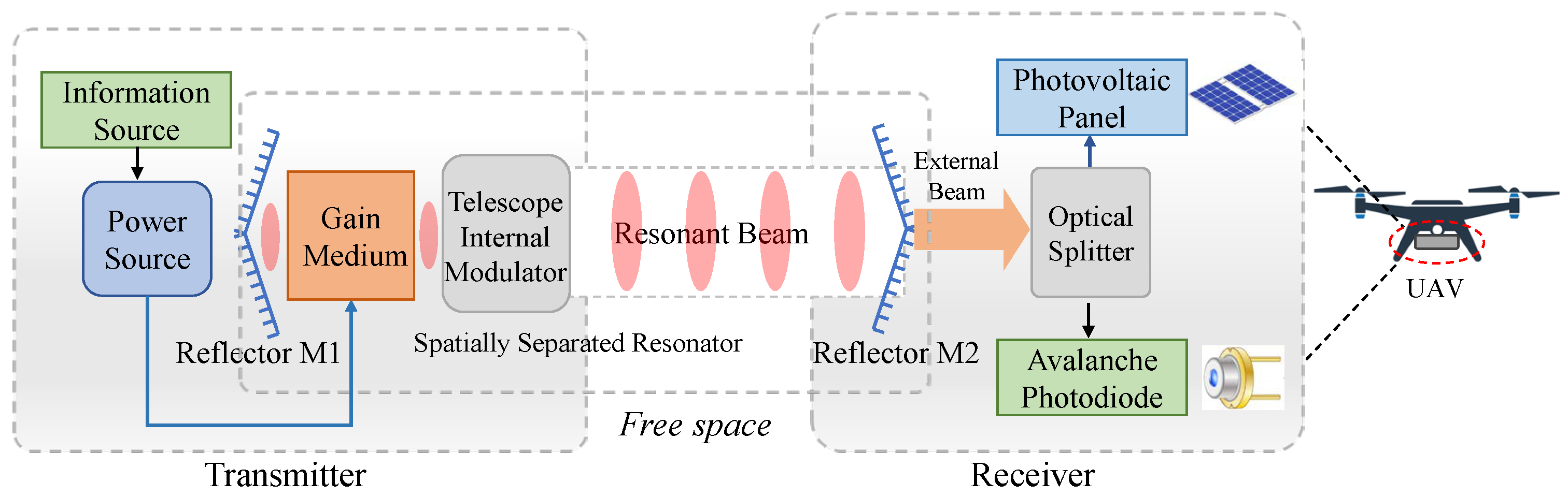
The system structure of the proposed RB-SWIPT scheme is briefly depicted in Figure 2. Overall, the system can be divided into three parts: the transmitter, the receiver, and the resonant path. The transmitter is mainly composed of a gain medium, a pump source, and a data loader. The data loader can load the electric signal into the pump source for data transfer. Then, the pump source releases a beam carrying the data signal in the form of optical radiation to the gain medium. The gain medium receives the energy and undergoes stimulated absorption, spontaneous emission, and stimulated emission, generating photons to form resonant beams. The receiver mainly includes three elements: a photovoltaic (PV) panel module, a beam splitter, and an avalanche photodiode (APD) module [27,28]. The beam splitter accepts the external beam output from M2 and splits them into two rays for independent energy harvesting and data receiving. The PV module receives one of the rays for energy harvesting, converting the optical energy into electrical power. The APD module captures the remaining rays for data reception, detecting the light signal. The spatially separated resonator is formed by reflectors M1 and M2 and a TIM. Among them, M1 and M2 constitute the resonant cavity for beam oscillation. The TIM is placed on the optical path in front of the gain medium. In this work, TIM denotes a passive telescope-based intracavity optical structure. It changes the phase front of the resonant beam and compresses the beam spot so that the beam can better match the small aperture of the semiconductor gain medium. Under the existing process conditions, through reasonable component layout and circuit design, the receiver of the RB-SWIPT system can be integrated into a variety of IoT sensors or devices to support their demand for power and communication. An illustrative application of this integration is on an unmanned aerial vehicle (UAV), achieving energy supply and information transmission, as depicted in Figure 2.
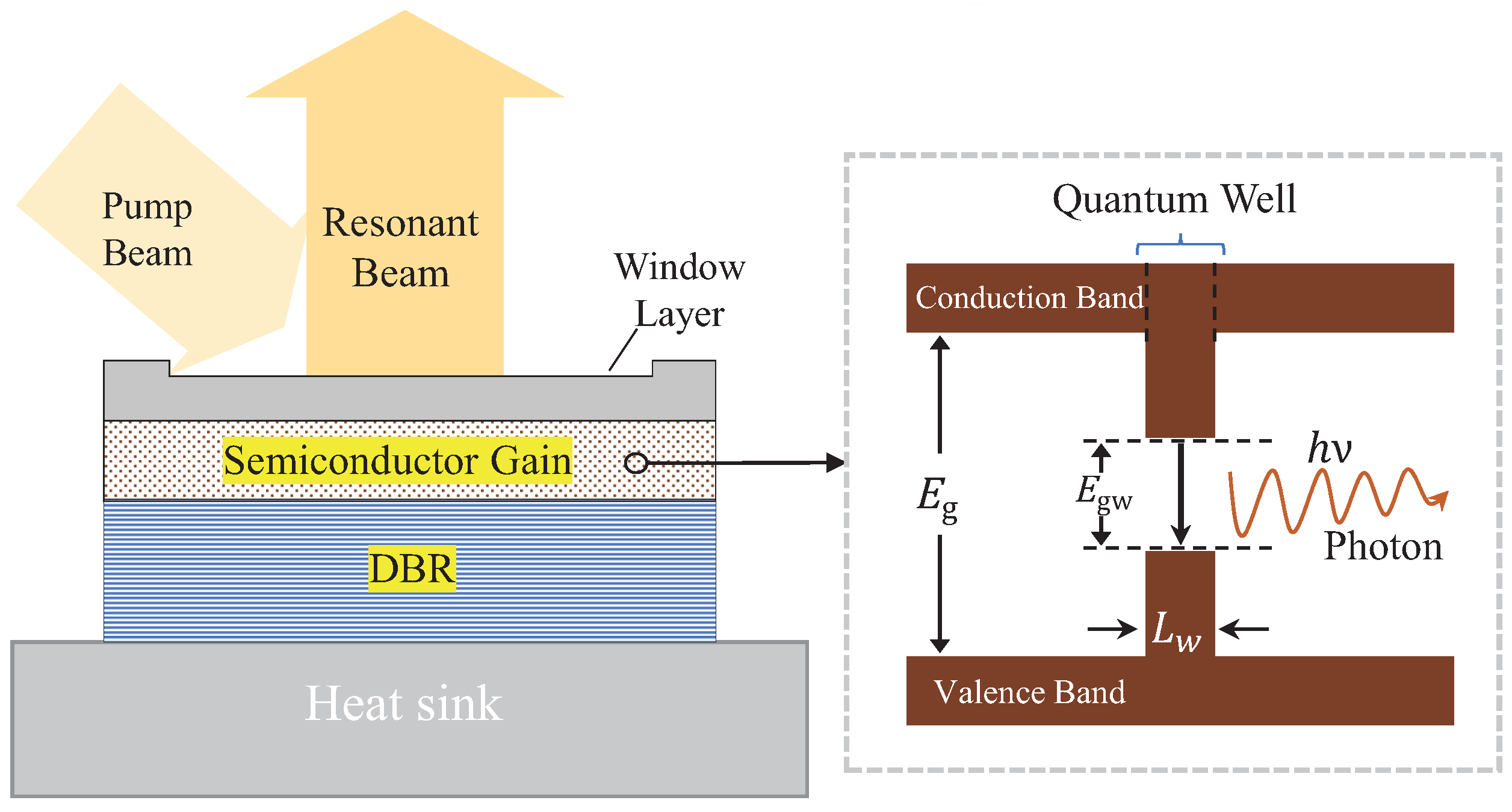
The RB scheme presented in this paper applies GaAsP-based semiconductor materials to compose the gain medium for enhanced efficiency. Semiconductor material utilizes the recombination of electrons in the conduction band and holes in the valence band to generate stimulated radiation [29], which has the following characteristics: (1) The materials used in the window layer, active region, and distributed Bragg reflector (DBR) layers of the gain medium have different band gaps, forming potential barriers. It will confine electrons and holes within the gain area, which is conducive to the recombination of electrons and holes. (2) The active area and the cladding layers have a refractive index difference. When photons reach the material boundary, they are reflected back to the active region. As a result, the light field can be restricted in the active area, which causes more stimulated radiation generation. (3) The semiconductor gain can be made as a hetero-junction quantum well structure. This structure (Figure 3) can further reduce the thickness of the active layer to the nanoscale and produce quantum effects, which further strengthen the confinement of carriers and optical fields and decrease the energy-level difference from E g to E g w [30,31]. Therefore, compared with the solid-state gain medium used in the original RB system, the semiconductor gain medium mainly contributes to efficiency improvement by increasing pump absorption and reducing the threshold power.

2.2. Resonant Beam Power and Conversion Efficiency

In the gain medium of the proposed optical system, photons are generated and subsequently propagate within the cavity. This process results in the formation of a resonant beam. The resonant beam is used as a carrier for transmitting both energy and signal to the designated receiver.
To assess the transmission efficacy of the system, the beam power output at reflector M2 serves as a crucial figure of merit. Additionally, the system exhibits a characteristic threshold power due to inherent energy losses. The output beam is only generated when the input power surpasses this threshold condition. Furthermore, the relationship between the input and output power is governed by a conversion efficiency ratio. This ratio is a function of the energy conversion process occurring at each stage within the system. Based on the cyclic power principle and materials characteristics of the gain medium [32,33], the external beam power can be defined as follows:
P beam = P in P th η s ,
where P in denotes the input electric power, P th revdenotes the threshold power, and η s is the slope efficiency.
The slop efficiency η s is related to the system structure such as the reflectivity of M1, which can be depicted as follows:
η s = η pc η pa λ pump ln R 2 λ beam ln R 1 R 2 V ,
where R 1 and R 2 denote the reflectivity of the reflectors M1 and M2, η pc is the pump conversion efficiency, λ beam ,   λ pump represent the wavelength of resonant beams and pump beams, and V = V c V d expresses overall energy losses, which mainly include constant loss V c (absorption dispersion of reflectors and air, internal loss in the gain) and beam diffraction loss V d .
The threshold power P th is determined by the gain medium, which can be expressed as follows:
P th = A s h c l N th λ η pc η pa τ ,
where A s expresses the effective active cross-section, h denotes the Planck constant, c is the speed of light in vacuum, λ represents the beam wavelength, l is the length of the gain medium, N th denotes the threshold carrier density in gain medium, η pa expresses the pump absorption efficiency, and τ is the carrier attenuation time.
Specifically, the carrier attenuation of the gain medium τ can be expressed as follows [33]:
τ = ( α + β N th + γ N th 2 ) 1 ,
where α , β , and γ express the recombination coefficients of the gain medium. N th is related to the gain factor, which can be described as follows:
N th = N 0 exp ( g / g 0 ) ,
where g 0 is the gain coefficient under low pump power, N 0 denotes the transparency carrier density, and g expresses the saturation gain coefficient.
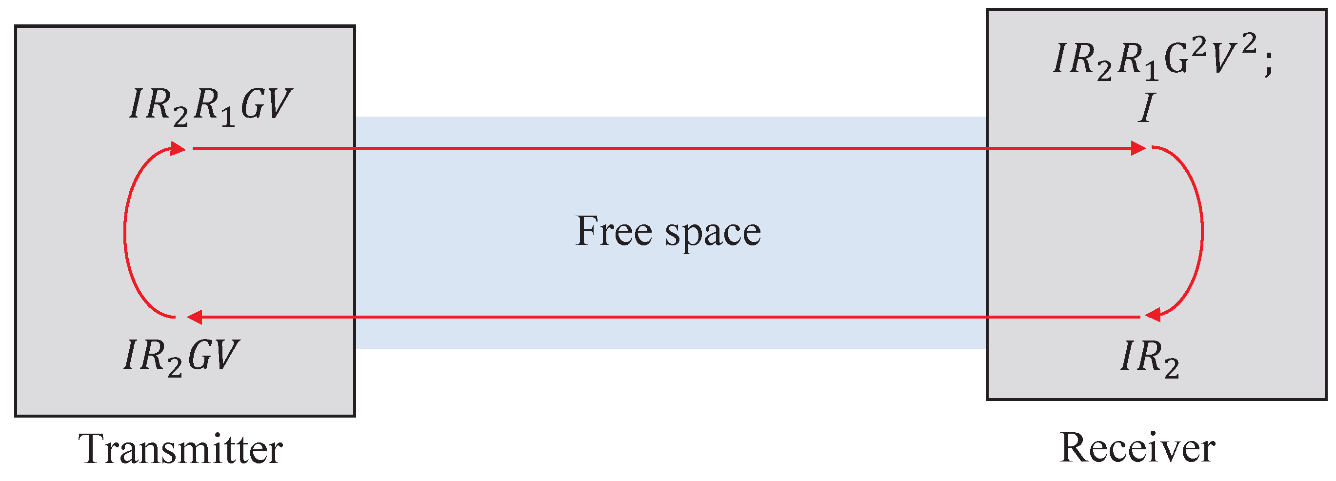
To define the parameter g, it is essential to analyze the energy saturation condition, characterized by an equilibrium between gain and loss within the system [32]. According to Figure 2, the spatially separated resonator cavity includes reflectors M1 and M2, TIM, and gain medium. During the propagation of the resonant beam within the cavity, optical elements, notably M1, either absorb or reflect a portion of the beam, resulting in energy losses. Conversely, energy is gained in the gain medium. Consequently, if the beam, after completing one round-trip within the cavity, returns to its point of origin with its energy unaltered, it can be inferred that the system has attained a state of equilibrium between loss and gain. This specific equilibrium state is referred to as the saturation condition. From Figure 4, after one round-trip energy cycle, the initial energy density will become I R 2 R 1 G 2 V 2 from I. When the saturation condition is satisfied, the I R 2 R 1 G 2 V 2 should equal to I, and the relationship of the parameters is as follows:
R 1 R 2 G 2 V 2 = 1 ,
where G = exp ( Γ g l ) expresses the overall gain factor (each time the beam travels through the gain, the beam energy intensity will increase by G times), R 1 and R 2  denote the reflectivities of M1 and M2, respectively. At this time, g is depicted as follows:
g = ln ( R 1 R 2 V 2 ) 2 l .
Further, taking (7) into (5), the N th can be denoted as follows:
N th = N 0 ( R 1 R 2 V 2 ) ( 2 g 0 l Γ ) 1 ,
where Γ is the longitudinal confinement factor.
Finally, based on the aforementioned formulas, the power P beam presented in (1) can be depicted. In the end, the beam transmission efficiency can be defined as follows:
η b = η pc η pa λ pump ln R 2 λ beam ln R 1 R 2 V 1 A s h c l N th λ η pc η pa τ P in .

2.3. Beam Transmission Description and Diffraction Loss

To analyze the resonator structure, the beam transmission process in the resonator should first be described. In this paper, we adopt beam vectors and transmission matrices to define the beam propagation. Specifically, based on the rectilinear propagation characteristics of the beam, we can describe it as  r = ( x , θ x ) , where x expresses the position parameter on the coordinate axis and θ x represents the propagation direction of the beam. Assuming a beam originates at a specific point and propagates in free space from x 1 to x 2 , with an initial transmission angle denoted as θ 1 , the beam’s trajectory can be represented using vector notation. Initially, the beam vector is expressed as r 1 = ( x 1 , θ 1 ) . As the beam progresses along its path to a position z, its vector representation evolves to r 2 = ( x 2 , θ 2 ) , indicating the change in both position and transmission angle. The conversion from r 1 to r 2 can be expressed using the matrix M , which is r 2 = M r 1 . Moreover, when the beam passes through a series of optical components, the entire process can be expressed as the matrices of these components multiplied in the corresponding order.
By employing the aforementioned beam vectors and the transmission matrices, it is possible to define the optical elements and characterize the beam transfer within the cavity. First, we adopt it to depict the reflectors. The reflectors we introduce in the scheme involve a convex lens (focal length: f) and a reflective mirror. The reflective mirror is located at the exit pupil of the lens with distance d, and its surface is flat (infinite focal length). Using the typical matrix expression of lenses and mirrors [32], the reflector can be described as follows [34]:
M r = 1 f 0 1 1 0 1 / f 1 1 d 0 1 1 0 0 1 1 d 0 1 1 0 1 / f 1 1 f 0 1 = 1 0 1 / f r 1 ,
where
f r = f 2 2 ( d f ) .
Reflectors can reflect incident beams back toward the parallel path of the original one, which is a precondition of the self-alignment [16]. To realize ideal retro-reflect in the proposed reflectors, we design d = f , which denotes the mirror is put at the focal point of the lens.
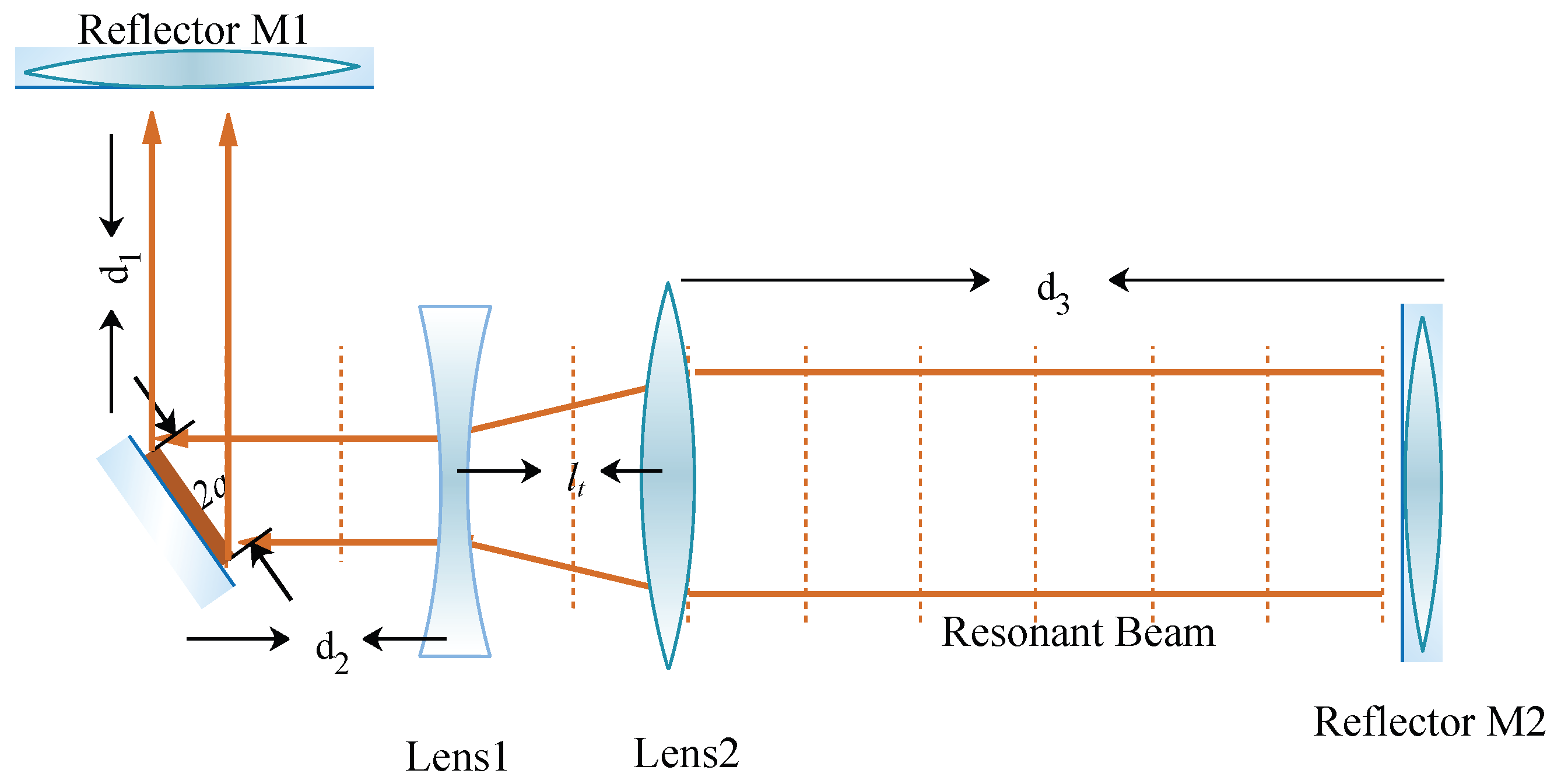
To effectively compress resonant beams, we have introduced the TIM technique and employed matrix representation to characterize and describe the TIM. As shown in Figure 5, lenses L1 and L2 with focal length f 1 and f 2 compose the TIM. The TIM consists of a convex lens and a concave lens with collinear optical centers. The focal point of the convex lens in the direction of the concave lens coincides with the negative focal point of the concave lens. This configuration compresses the beam spot while allowing the output beam to remain collimated. The TIM can be expressed as follows:
M TIM = M L 2 M l M L 1 = 1 0 1 f 2 1 1 l t 0 1 1 0 1 f 1 1 = 1 M l t 0 M ,
where M = f 1 / f 2 .
Building on the previously mentioned matrices and referring to Figure 5, we can define the single-pass beam transmission in the resonator. Taking reflector M1 as the starting point, the beam propagating in the cavity will pass through lens 1, lens 2, and reflector M2 in sequence. This process can be expressed using the following matrix representation:
M c = M M 2 M d 3 M L 2 M l M L 1 M d 2 M d 1 M M 1 = 1 0 1 f r 2 1 1 d 3 0 1 1 0 1 f 2 1 1 l t 0 1 1 0 1 f 1 1 1 d 2 0 1 1 d 1 0 1 1 0 1 f r 1 1 ,
where M M 1 , M M 2 , M L 1 , and M L 2 express the matrix of reflectors M1 and M2 with effective curvature factors ρ 1 and f r 2 and lenses L1 and L2 with focal length f 1 and f 2 . M d 1 , M d 2 , M d 3 , and M l express the beam transfer in the space with distances d 1 , d 2 , d 3 , and l t .
To accurately determine the diffraction loss, it is essential to depict the beam’s distribution along the vertical propagation direction. The beam spot effectively characterizes the beam’s vertical distribution, with its radius being a commonly used metric to evaluate the beam’s lateral amplitude at a given point. Given that the intensity cross-section of the beam is circular, we utilize the spot radius as the key parameter for this evaluation. According to [35,36], the beam spot radius on the reflectors of the resonant cavity can be defined by M c . Furthermore, given that the gain medium is strategically positioned on the transmitter side, and considering that the distance d 1 is relatively small, it can be inferred that the spot size on the gain medium is approximately equivalent to the spot size on reflector M1. In this case, the beam spot radius on the gain medium can be given by the following:
M c = A c B c C c D c ω g = λ 2 B c D c π 2 A c C c 1 / 4 ,
where A c , B c , C c , and D c are the matrix elements of M c , which is depicted in (13); λ is the wavelength of the resonant beam. Further, the beam diffraction loss V d can be defined as follows [37]:
V d = 1 exp ( 2 a 2 / w g 2 ) ,
where a denotes the radius of gain medium.

2.4. Electric Power Output and Spectral Efficiency

As outlined in Section 2.1 the external beam carrying the signal will emerge from reflector M2 at the receiver’s end. Subsequently, a beam splitter is employed to divide this external beam into two distinct paths. One portion is directed towards the photovoltaic (PV) cell, facilitating electric energy harvesting (EH). The other portion is captured by the avalanche photodiode (APD) for the purpose of data reception.
(1)
Electric Power Output
Firstly, part of the external beam separated by the beam splitter is transmitted to the surface of the photovoltaic cell through a homogenizing waveguide. Then, the beam will be converted into electrical power output through photoelectric conversion. This process can be briefly expressed by the following formula [38]:
P p = μ P beam , P E out = η p P p + P pth ,
where μ is the power split ratio, and P p expresses the beam power received by the PV. The parameter η p is the slope efficiency of photoelectric conversion, and P pth is the threshold power of the PV. It should be noted that, in order to simplify the simulation process, P E out is represented using a linear model. This approach is based on the experimental findings presented in [39], and it assumes ideal conditions for both heat dissipation and the receiving area of the PV system. In practice, the beam energy absorbed by PV is limited, it is expected that the conventional linear EH model is only accurate for the specific scenario when the received powers at the receiver is in a constant power range and the nonlinear EH model has a better applicability [40]. Further, the end-to-end energy conversion efficiency is depicted as follows:
η E = η p P p + P pth P in .
(2)
Spectral Efficiency
The residual portion of the external beam, segregated by the beam splitter, is incident upon the APD. The APD functions to convert this optical signal into an electrical signal, concurrently facilitating data reception. This conversion process can be illustrated as follows:
P D = ( 1 μ ) P beam , I D out = ν P D ,
where I D out is the photon current generated by the APD, ν is the optical-to-electrical conversion responsivity of the APD.
Moreover, photoelectric conversion will produce thermal noise and shot noise when APD is receiving light. Among them, the thermal noise can be expressed by the following formula [41]:
n thermal 2 = 4 k T B x R L ,
where k is the Boltzmann constant, B x is the bandwidth, T is the temperature, and R L is the load resistor. In addition, the formula about the shot noise factor is [41]
n shot 2 = 2 q ( I D out + I bg ) B x ,
where q is the electron charge, and I bg is the background light induced photon current. At this point, the additive white Gaussian noise (AWGN) of the communication module can be defined:
N M 2 = n shot 2 + n thermal 2 .
Finally, we can obtain the spectral efficiency of the communication link as follows [42]:
C ˜ = 1 2 log 2 ( 1 + I D out 2 2 π e N M 2 ) ,
where e is the natural constant.

3. Numerical Results

In this section, we evaluate the system performance by analyzing the resonant beam distribution, received beam power, output electric power, and channel capacity.

3.1. Resonant Beam Distribution

In order to match the semiconductor gain, the proposed RB system incorporates a built-in TIM, which modulates the beam’s phase to achieve beam compression. To evaluate the compression performance, we utilize the beam spot radius, as defined in the previous chapter, analyzing its variations with respect to different structural parameters.
(1)
Parameter Setting
The gain medium is composed of GaAsP semiconductor material, which generates light at a 980 nm wavelength. It is obliquely positioned 20 mm from M1. As detailed in Section 2.3  f r 1 is set to infinity ( d = f ). To maintain par-axial beam propagation, the focal length f r 2 of M2 is set as a variable. The TIM is positioned on the side of the gain medium, with its position parameter d 2 set to 20 mm relative to the gain chip. The concave lens within the TIM is designed with a focal length of f 1 = 5 mm . We investigate the impact of the end-to-end distance d 3 (ranging from 2 m to 10 m ) and the TIM structure parameter M. Finally, given that the beam spot radius varies with distance, we utilize the maximum spot radius on the gain medium, ω g , Max , as a critical metric for evaluation.
(2)
Calculation Results and Analysis
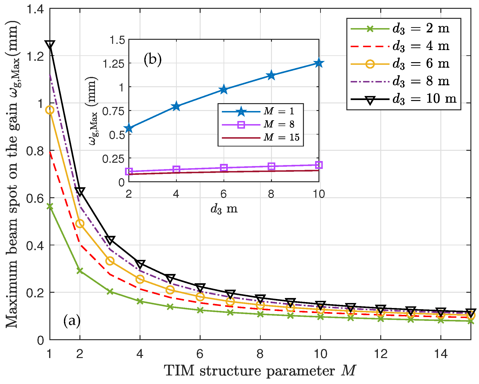
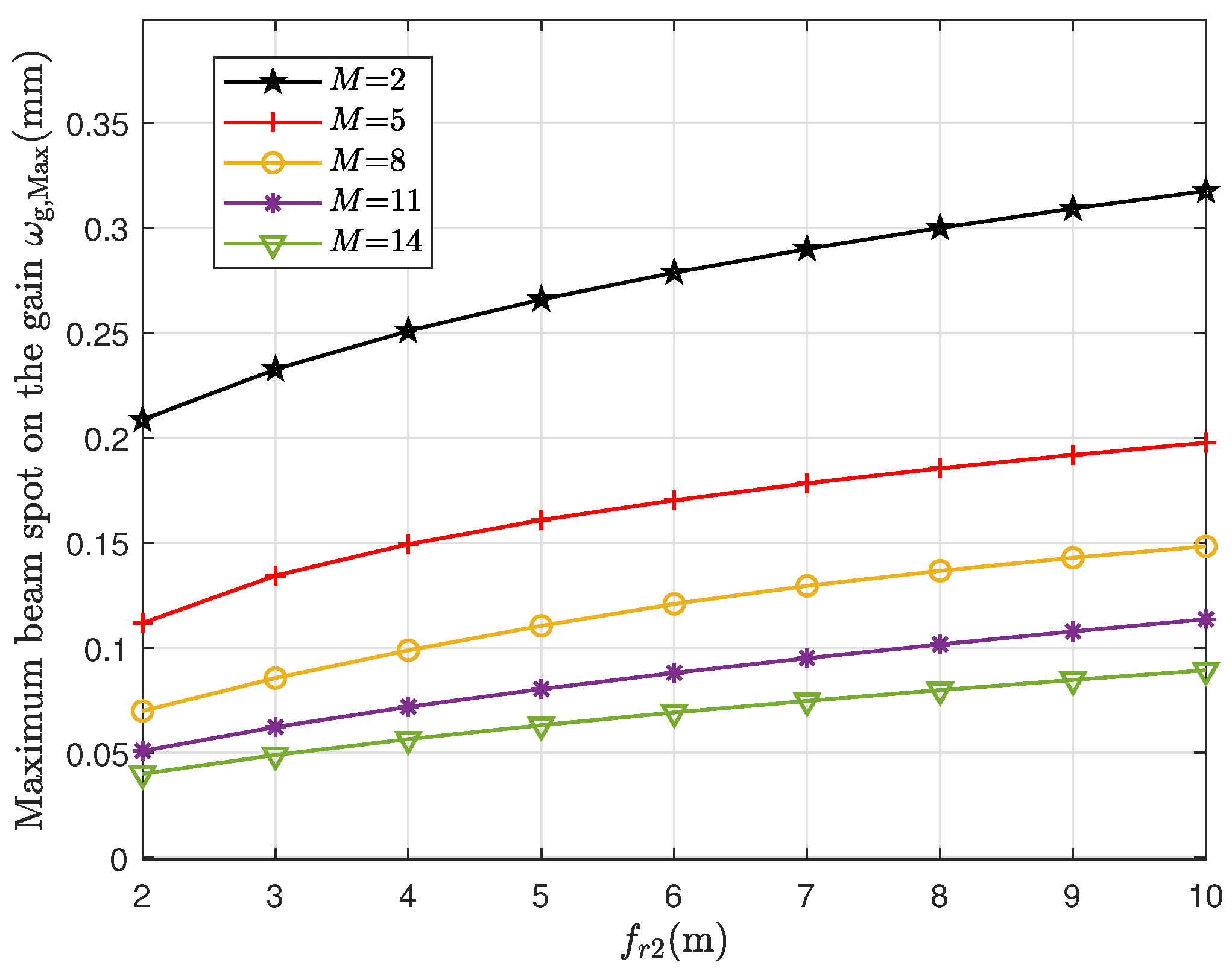
Figure 6a presents the calculated results, showing the relationship between the TIM structure parameter M and the maximum beam spot radius ω g , Max . As M increases, ω g , Max exhibits a downward trend. Specifically, for M values ranging from 2 to 6, the beam radius rapidly decreases. For M > 10 , the beam spot radius’s decrease becomes more gradual, indicating a limited compression capacity. Moreover, for large values of M, the beam spot compression tends to stabilize. Furthermore, if the end-to-end distance d 3 is large, ω g , Max will increase. Quantitatively, the incident beam is compressed from 1.2 mm to approximately 0.1 mm , representing a compression factor of 12 × . Figure 6b depicts curves of ω g , Max as a function of d 3 . As shown, in the original scheme without TIM ( M = 1 ), the beam radius increases significantly as d 3 increases. In contrast, the proposed scheme with TIM exhibits a more gradual increase. Numerically, the ω g , Max value for the proposed scheme remains below 0.25 mm , whereas for the original scheme, it exceeds 0.5 mm . Furthermore, we analyze the influence of the focal length f r 2 of reflector M2 on beam compression. Figure 7 shows the maximum beam radius on the gain medium as a function of f r 2 . As depicted, ω g , Max exhibits an upward trend as f r 2 increases. Concurrently, the curves show a downward shift with an increase in M. Overall, an increase in f r 2 tends to have a detrimental effect on beam compression, as evidenced by the enlargement of the beam spot.
From the aforementioned analysis, it can be preliminarily concluded that the TIM effectively compresses the beam across varying end-to-end distances. As discussed in Section 2.1 and Section 2.2, this capability ensures that the resonant beam can enter the micron-sized semiconductor gain medium without significant energy loss.

3.2. Received Beam Power

According to Section 2.1, after the energy accumulates, the external beam will eventually emerge from reflector M2. Then, it will enter the PV and APD, respectively, under the function of the beam splitter, realizing the electric power output and data reception. Usually, we can adopt the received beam power P beam to evaluate the end-to-end beam transmission performance.
(1)
Parameter Setting
According to the material properties of GaAsP, we can obtain the characteristic parameters such as light quantum, gain factor, etc., as listed in Table 1. Furthermore, we adopt a typical laser diode as the pump source whose electro-optical conversion efficiency η pc and absorption efficiency η pa are 0.6 and 0.85. In addition, the effective active cross-section A s of the gain is set as 3 × 10⁻⁴ cm2, the constant loss V c is 0.99, the geometric radius of gain medium a is 0.5 mm, the pump beam wavelength is 808 nm, the reflectivity of the mirror in M1 is 0.999, and the end-to-end transmission distance is 10 m.
(2)
Calculation Results and Analysis
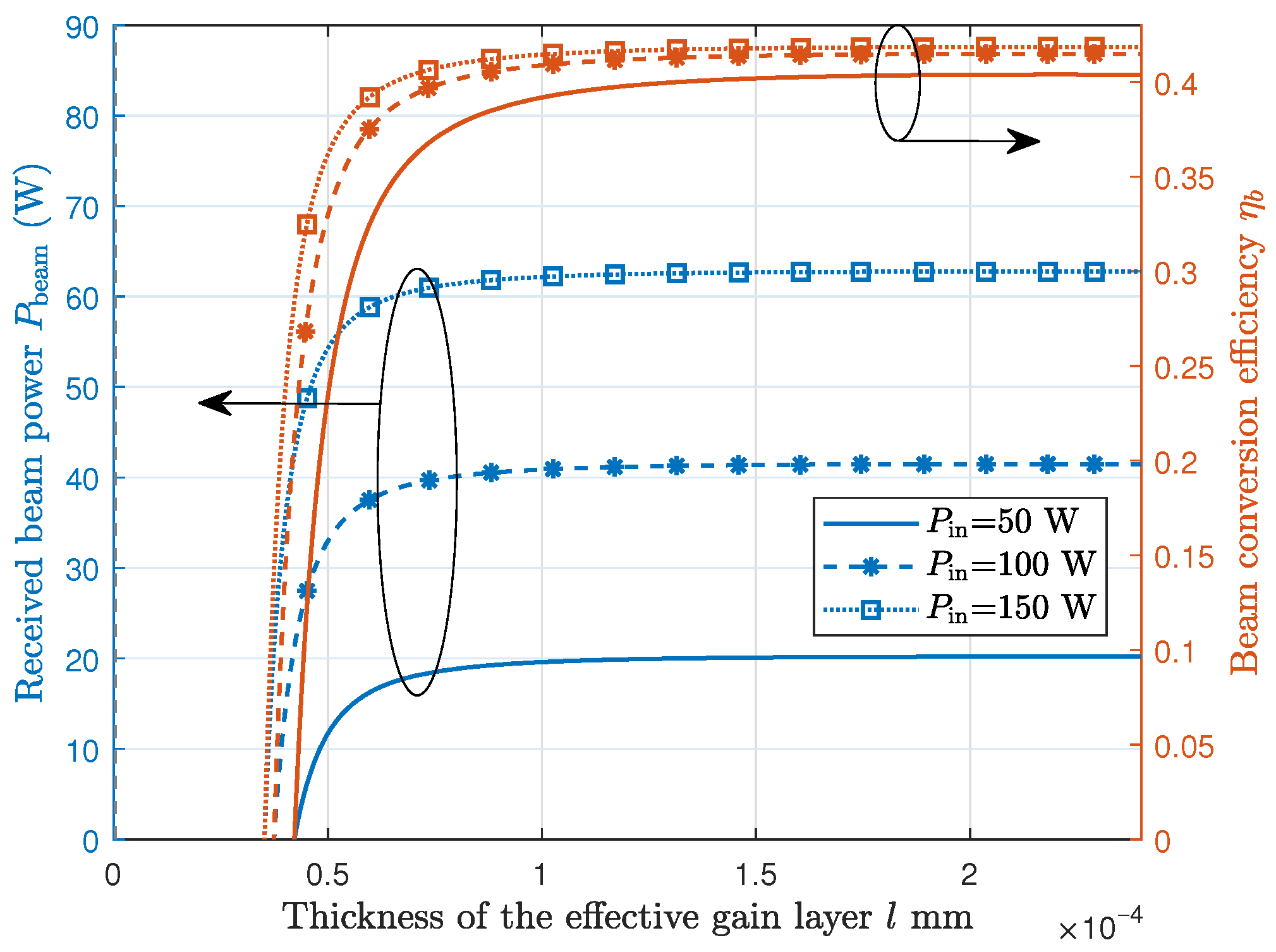
Figure 8 describes the relationship among the received beam power ( P beam ), conversion efficiency ( η b ), and the thickness of the effective gain layer (l). It is observed that as l increases, both P beam and η b exhibit a rising trend. However, this upward trend tends to plateau when the thickness of the effective gain layer reaches a larger value. Consequently, the influence of l on both P beam and η b becomes less pronounced. Moreover, when P in takes a large value, curves of P beam and η b will move up. Numerically, the received beam power can be 60 W and beam conversion efficiency can be 40% as P in = 150 W, and the increase in P in has a significant impact on P beam but only a limited impact on η b . Overall, by appropriately increasing the thickness, we can enhance the performance of beam transmission.
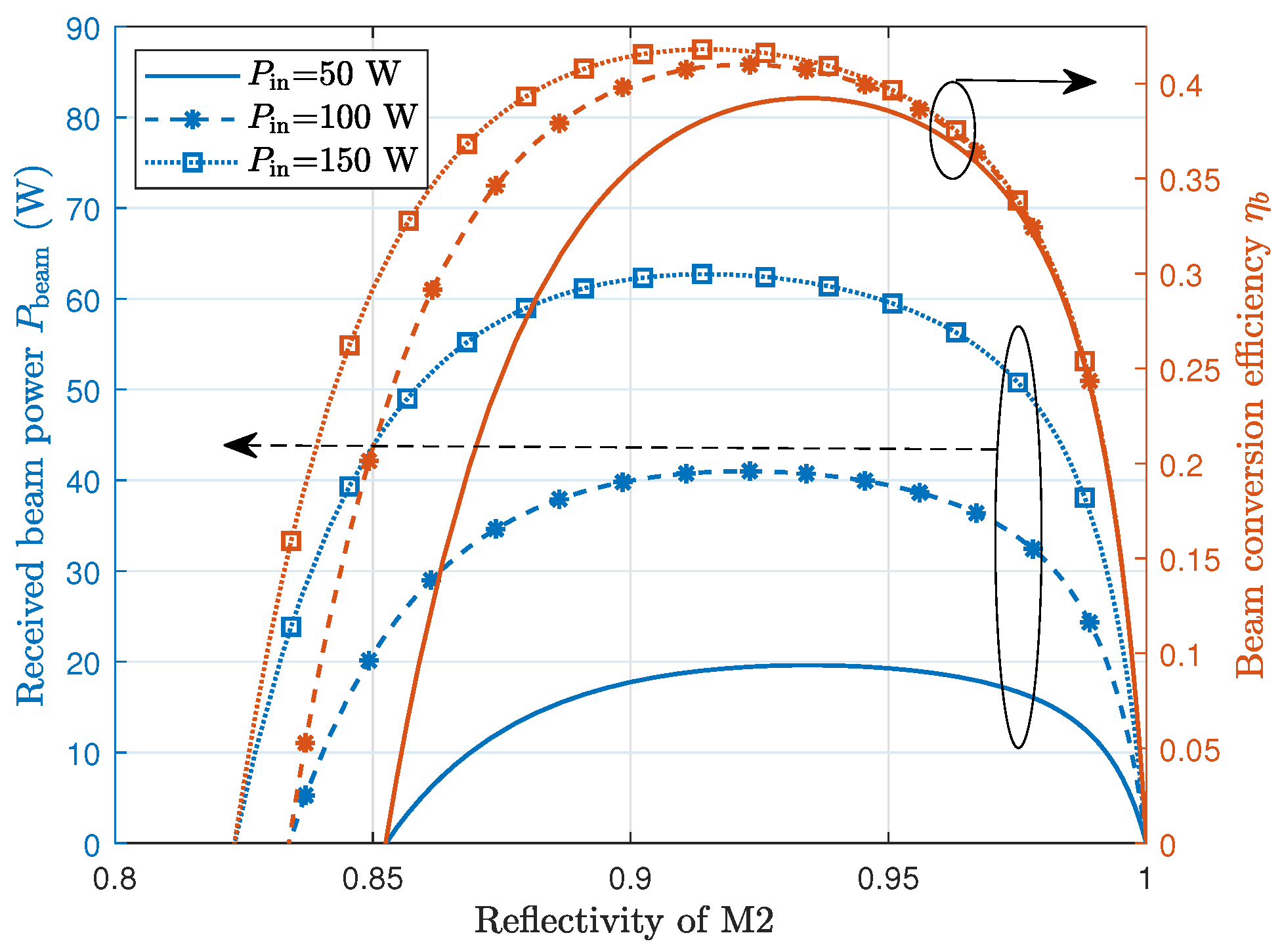
Figure 9 presents the curves of received beam power and conversion efficiency versus the reflectivity of M2. From the blue lines in the graph, it is evident that as the reflectivity of mirror M2 ( R 2 ) changes from 0.8 to 1, both the received beam power and the beam conversion efficiency initially increase and then decrease. Moreover, as the input power is increased, the curves representing the beam power ( P beam ) and the beam conversion efficiency ( η b ) shift to the left and ascend. Numerically, the maximum value of P beam and η b are obtained when R 2 is in the range from 0.9 to 0.95.
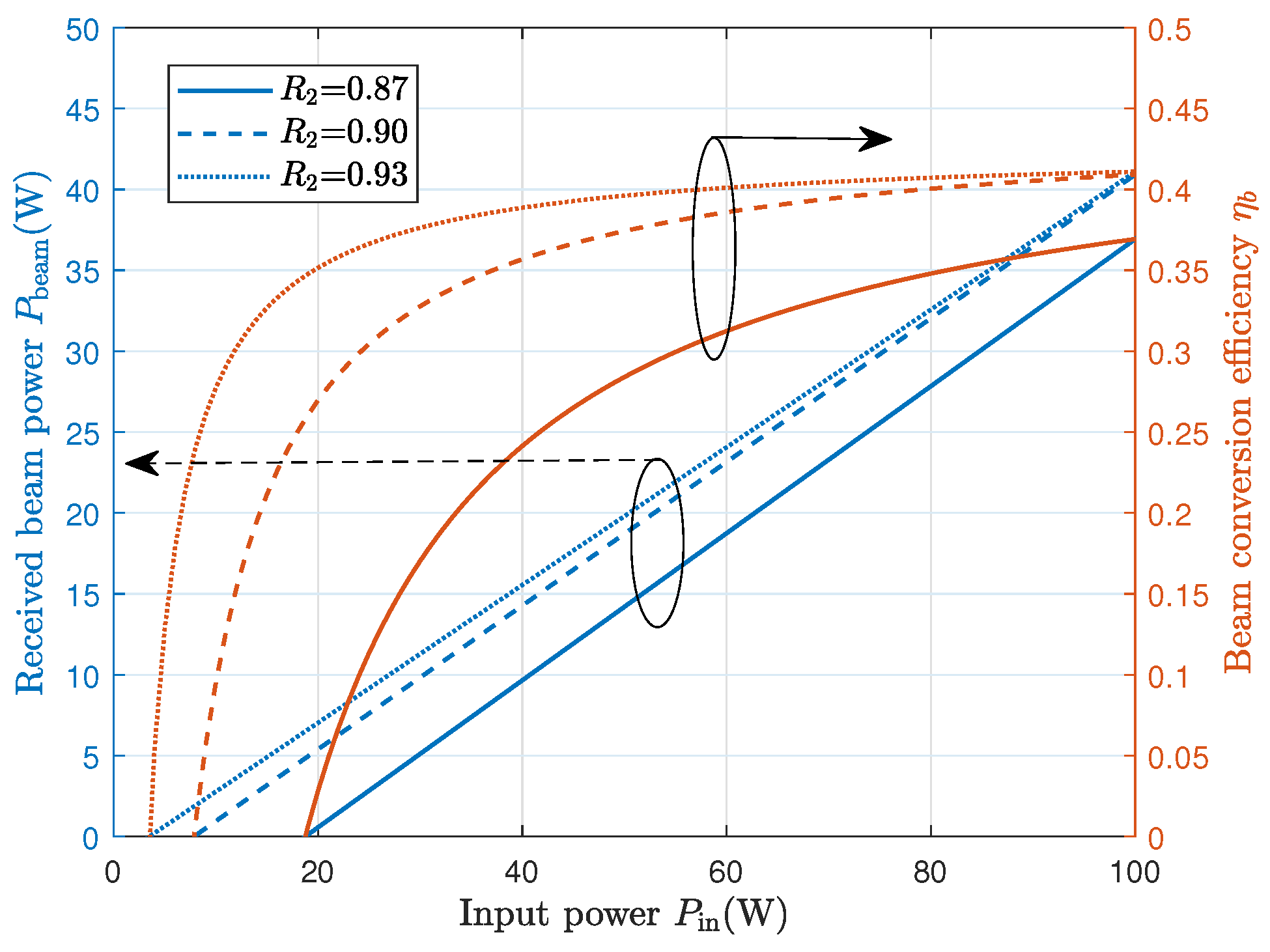
In Figure 10, we analyze P beam and η b as functions of the input power P in . According to the blue lines, the P beam increases as P in increases, which presents a positive linear relationship with P in . Moreover, the slope and intercept of lines are affected by R 2 . A large value of R 2 is beneficial for reducing the threshold power (line intercept). Besides, from the red curves, η b is also enhanced as P in increases. However, different from P beam , the curves are nonlinear and gradually flatten out.
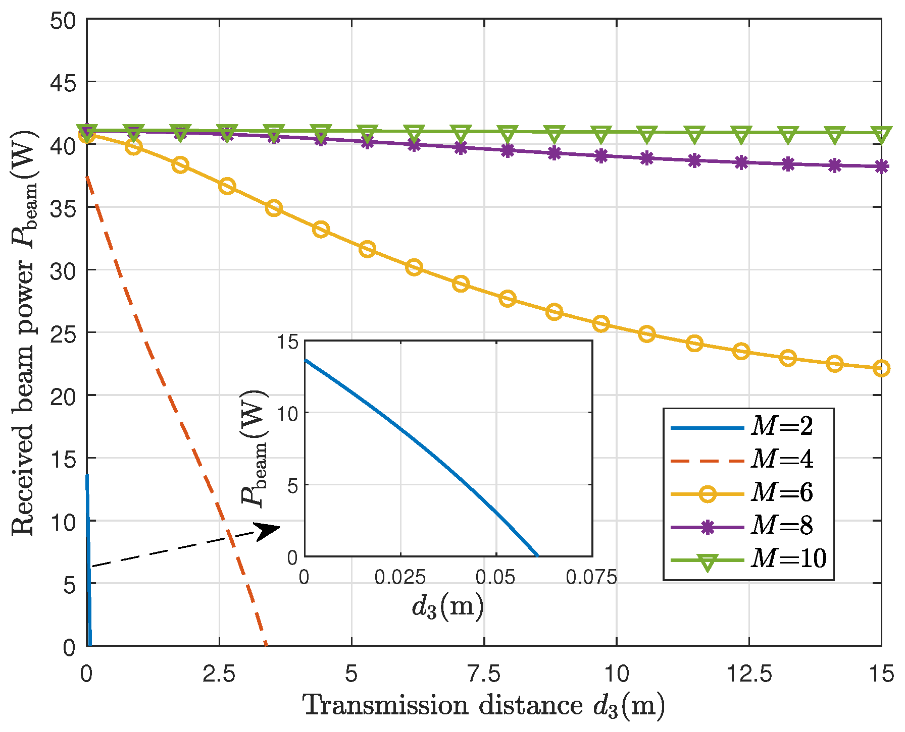
Further, we evaluate the performance of received beam power P beam as the function of transmission distance d 3 , which is shown in Figure 11. As can be seen, curves of P beam present a downtrend with the increase in d 3 which proves the negative impact of the transmission loss on beam output (Section 2.3). Moreover, as the value of M increases, the curves become flatter. This indicates that the transmission loss can be suppressed by the TIM. Numerically, the value of P beam can maintain 40 W output over a 15 m distance.

3.3. Output Electric Power and Channel Capacity

To evaluate the received beam power, we have examined the factors influencing both P beam and η b . Additionally, it is necessary to analyze the performance of the PV cell and the APD in the context of SWIPT.
(1)
Parameter Setting
To evaluate the SWIPT performance, the PV and APD structure parameters should be defined. According to [39], PV cell structure parameters η p and P pth are set as 0.3487 and 1.535 W, respectively. In the proposed system, the environment temperature is taken as T = 300 K, the electronic charge q is 1.6 × 10 19 C, and the Boltzmann constant k is 1.38 × 10 23 J/K. The APD for light signal receiving involves commercial sensors with 980 nm wavelength. Then, based on [41,43,44,45], we set the conversion responsivity of the APD ν = 0.6 A/W, the noise bandwidth B x = 811.7 MHz, the background current I bg = 5100 μA, and the load resistance R L = 10 kΩ.
(2)
Calculation Results and Analysis
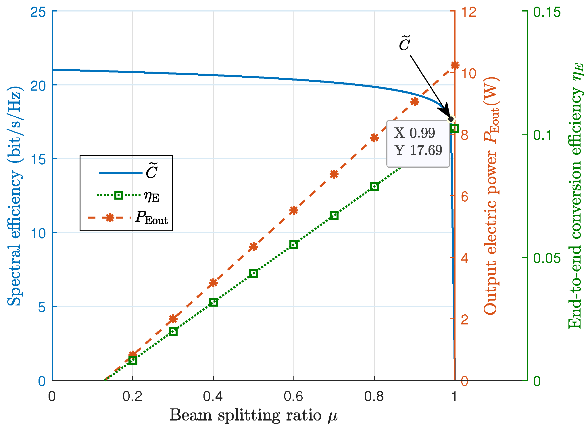
Figure 12 depicts the curves of spectral efficiency, output electric power, and end-to-end conversion efficiency versus the beam splitting ratio. Observing the blue line, the entire curve exhibits a downward trend as μ increases. Initially, this decline is relatively gradual. However, when μ exceeds 0.8, C ˜ starts to decrease sharply.
From the red and green lines with markers, it is evident that both P Eout and η E exhibit a positive linear relationship with μ . Their values increase as μ increases. Numerically, the spectral efficiency C ˜ reaches 17.69 bit/s/Hz when μ is set to 0.99, at which point P Eout and η E are also high. Therefore, this value of μ can be chosen as the beam splitting ratio to achieve high-efficiency SWIPT.
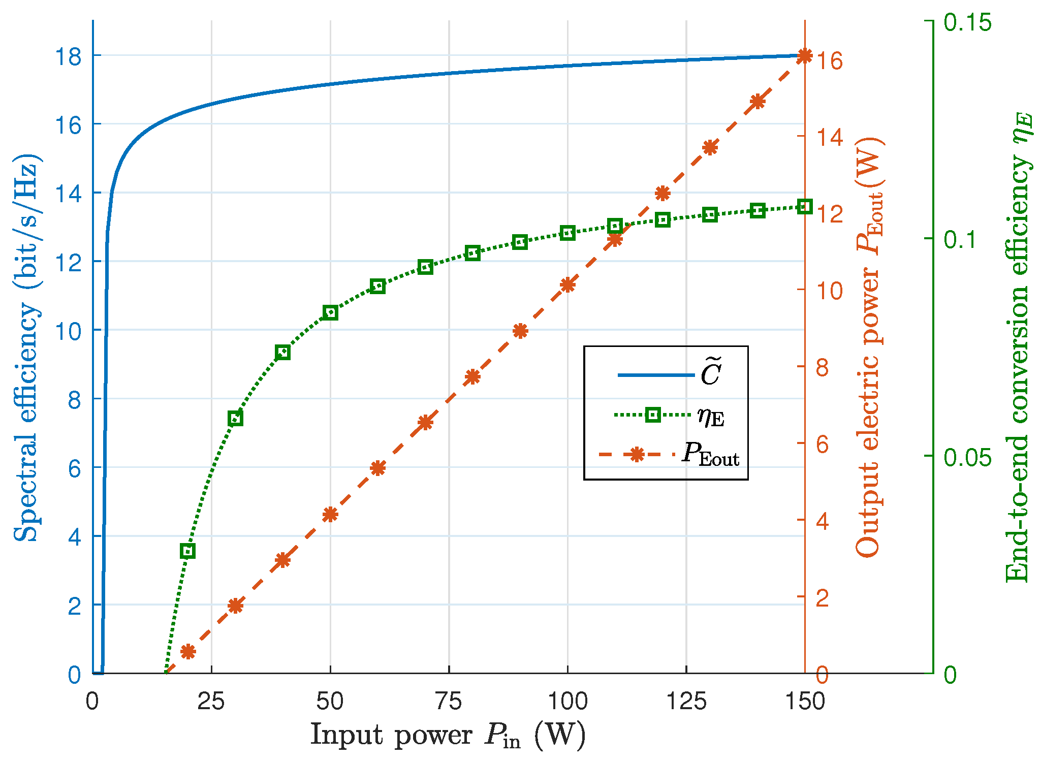
In addition, we explore the relationship of spectral efficiency, output electric power, and end-to-end conversion efficiency versus input power, which is presented in Figure 13. From the blue line, it is apparent that the spectral efficiency rapidly ascends to a larger value. In general, the greater the input beam energy, the higher the spectral efficiency the scheme achieves. However, this effect is somewhat limited. As the input power continues to increase, the system’s spectral efficiency tends to stabilize. For instance, when P in is increased from 50 W to 150 W, the spectral efficiency experiences only a modest increase of 1 bit/s/Hz.
Furthermore, as indicated by the red and green lines in Figure 13, both P Eout and η E exhibit a positive relationship with P in , where P Eout shows a linear trend and η E demonstrates a nonlinear one. Numerically, P Eout and η E can reach 16 W and 0.11, respectively, at P in = 150 W. Generally, by optimally matching the splitting ratio with the input power, the system’s data transmission spectral efficiency can achieve 16–18 bit/s/Hz, supporting 0–16 W of output electric power. This demonstrates the system’s potential for high-rate and high-power SWIPT.

3.4. Summary

In summary, after numerical evaluation and analysis, we conclude that the proposed RB SWIPT scheme is capable of providing 16 W electrical energy harvesting and 18 bit/s/Hz spectral efficiency for communication, with 11% energy conversion efficiency and 10 m transmission distance. Table 2 presents the performance comparison between our system and the existing architectures, clearly demonstrating the advantages of the proposed RB SWIPT system in delivering high power, maintaining high spectrum efficiency, and ensuring high energy conversion efficiency over long transmission distances. The improvement in end-to-end efficiency is not caused by a single factor. The semiconductor gain medium mainly reduces the threshold power and improves the pump absorption process. The TIM mainly reduces diffraction/aperture mismatch loss by compressing the beam spot on the gain medium. The output-coupler reflectivity R 2 further determines the tradeoff between intracavity buildup and useful beam extraction. Therefore, the predicted efficiency improvement is a combined result of the semiconductor gain medium, TIM-assisted beam compression, and output-coupling optimization.
The three most representative parameters are the output-coupler reflectivity R 2 , the TIM compression factor M, and the beam splitting ratio μ . First, R 2 determines the tradeoff between cavity feedback and useful output coupling, and it therefore strongly affects the resonant beam output power and beam conversion efficiency. Second, M changes the beam size inside the resonator and affects diffraction/aperture loss, especially when the resonant beam needs to be matched to the small semiconductor gain medium. Third, μ controls the power allocation between the PV module and the APD module. Increasing μ improves the harvested electric power and end-to-end conversion efficiency, but it reduces the optical power used for data reception and thus decreases the spectral efficiency.

4. Discussion

4.1. Transmission Model by Electromagnetic Field Propagation

In the aforementioned sections, we have developed an end-to-end beam transmission model based on linear optics using beam matrices. Additionally, considering the electromagnetic field characteristics of light waves, we can also adopt electromagnetic field propagation to conduct exact analyses for the amplitude and phase distribution of the light field. The theoretical framework for describing electromagnetic field propagation is derived from Maxwell’s equations, leading to the wave equations for electric and magnetic fields, as cited in [50]. Furthermore, according to the Huygens–Fresnel principle, during the propagation of light, the field distribution at any point is determined by the coherent superposition of the wavelets of the incident wave at that point [51]. By understanding the field distribution of the initial point light wave, denoted as u ( x , y ) , we can apply diffraction theory to express its field distribution at a specific point ’s’ on the transmission path as u ( x , y ) . This approach allows us to accurately represent the beam transmission within the resonator. Building on this, we can incorporate the boundary conditions of the resonator in our proposed system to describe the changes in the light field of the beam over a complete end-to-end cycle. Furthermore, by considering the beam generation from the self-reproductive mode, as mentioned in [52], as a criterion for stable output, we can determine the steady-state light field distribution.
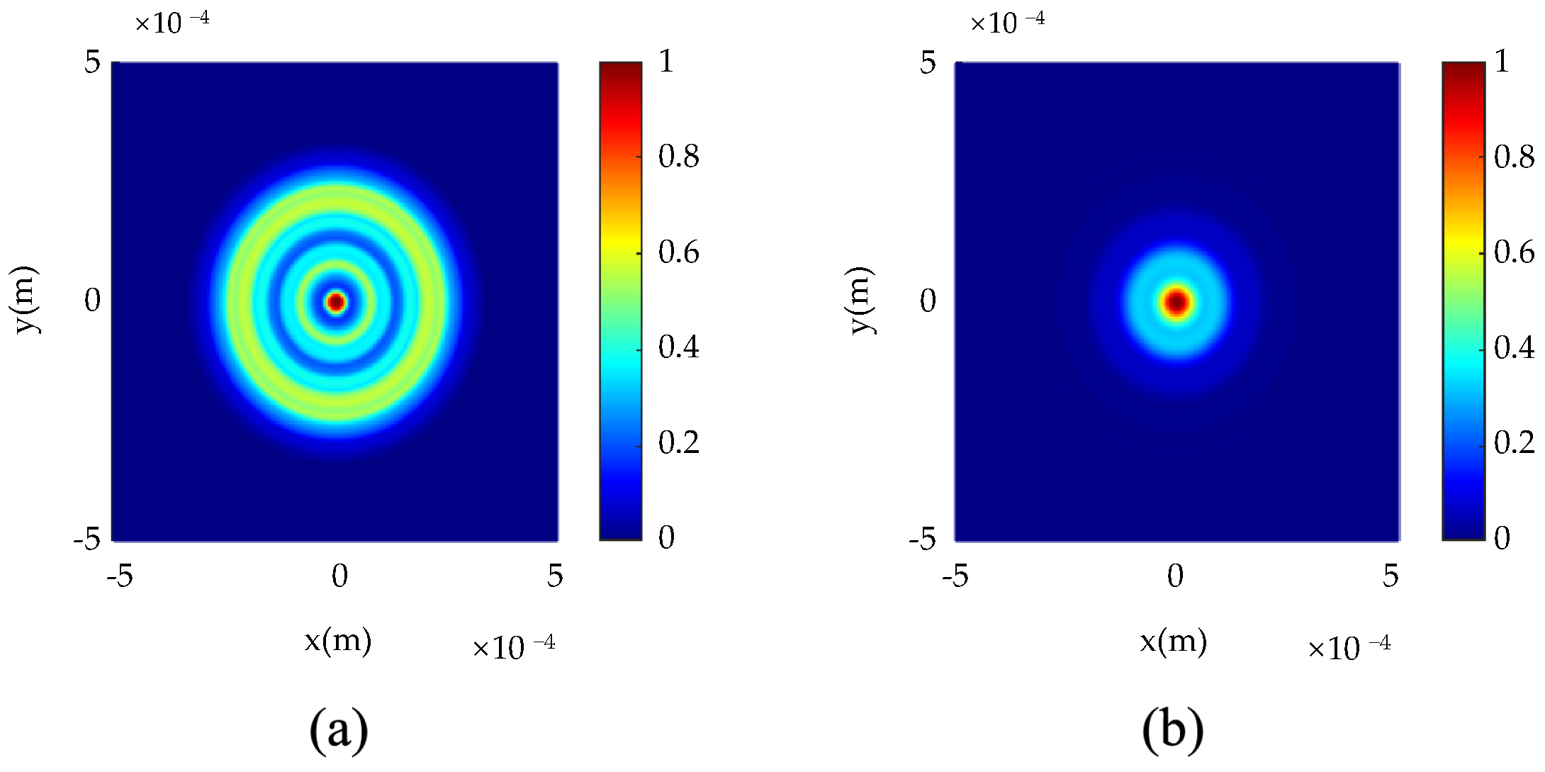
Figure 14 presents the field distribution on the gain medium based on the electromagnetic field propagation model. As can be seen, the incident beam on the gain medium has been effectively compressed in the proposed system with TIM. In contrast, the beam has a broader field distribution and lower beam quality (uneven distribution) in the original system without TIM. This analysis corresponds to the results obtained using the matrix model in Section 5, further verifying the feasibility of our proposed scheme. Recent progress in structured laser modes also provides useful context for understanding mode control in laser resonators [53]. Overall, electromagnetic field propagation analysis is beneficial for evaluating the beam’s quality, system structure, etc. However, it is important to note that as fast Fourier transform and the Fox–Li iterative method are employed in these calculations, they demand significantly more computing power and time compared to the transmission matrix method introduced in the second section of this paper. Future research will delve deeper into the benefits and results of this method.

4.2. Experimental Setup and Analysis

In this paper, we propose a high-efficiency RB charging and communication scheme, provide an analytical model, and evaluate system performance through simulation. To discuss the practical feasibility of the proposed scheme, we set up a preliminary optical test platform.
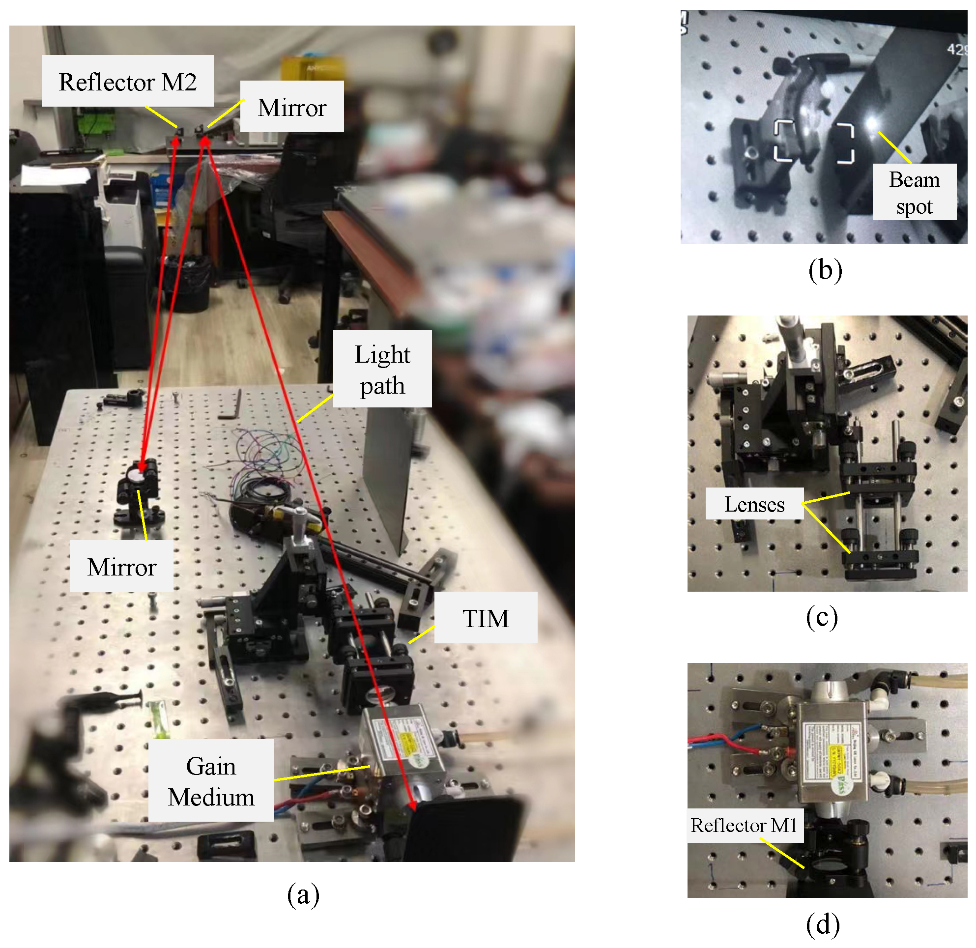
Figure 15 presents the setup photos of the experimental testbed. The testbed mainly includes reflectors, mirrors, telescope internal modulator (TIM), and the gain medium. As detailed in Section 2, the gain medium is responsible for generating photons through electro-optical conversion. The TIM, which consists of a series of lenses, compresses the incident beam to facilitate extended transmission distances. Beams are reflected by reflectors located at both the receiver and transmitter ends, oscillating back and forth in free space. Additionally, two mirrors with highly reflective coatings are placed on two optical workbenches to fold the light path to achieve equivalent transmission of tens of meters in an indoor environment. Utilizing infrared cameras for measurement, as depicted in Figure 15b by implementing a double-fold in the optical path using mirror, the system can demonstrate beam output at a distance of around 15 m. This achievement validates the system’s efficacy in long-range energy transmission and output, in stark contrast to the original scheme, which was limited to only 2.6 m [15].
The experimental observations in Figure 15 provide preliminary support for the optical feasibility of the proposed resonant beam structure. Specifically, the platform confirms that the resonant beam cavity can be constructed and that the beam can be formed and observed after the folded optical path, which is consistent with the beam-transmission analysis in the preceding sections. The TIM-assisted optical layout also supports beam compression and long-distance beam propagation in the cavity. Therefore, the experiment provides qualitative validation of the cavity construction and beam-transmission feasibility assumed in the analytical model. However, the present setup does not yet provide quantitative validation of the predicted output electric power, end-to-end conversion efficiency, or spectral efficiency.

4.3. Applications in IoT

As depicted in Figure 1 and Figure 2, the RB-SWIPT can support several sensors or devices for IoT, such as UAV, smartphones, etc. For instance, the UAV’s fuselage can be equipped with the RB-SWIPT station’s receiver module, enabling wireless charging through resonant beam. This feature is crucial when the UAV is tasked with collecting data from sensors, adjusting its flight path, or functioning as a ‘thing’ node in the IoT network. The use of resonant beam technology not only facilitates reliable data transmission but also helps maintain a higher state of charge for the UAVs. However, the original resonant optical system faced limitations in transmission distance and conversion efficiency due to energy losses, with a maximum transmission distance of only 2.6 m and a mere 1% conversion efficiency, as reported in [15]. These limitations hindered its application in UAVs. Thus, the innovative approach presented in this paper, which integrates a TIM structure and high-efficiency semiconductor gain medium, significantly enhances both the transmission distance and conversion efficiency. This improvement makes the application of the resonant beam system in UAVs feasible. Furthermore, we have developed a viable communication pathway that facilitates simultaneous energy transmission and information delivery. The establishment of a reliable optical communication channel addresses bandwidth and interference challenges, effectively integrating UAVs as functional nodes in IoT applications. Beyond the UAV application mentioned above, the RB-SWIPT system is versatile enough to be integrated with a wide range of real-time IoT terminals. Examples include human body sensors, cameras, smart doorbells, and other IoT devices. The implementation of this system can effectively address common challenges such as the need for extensive device wiring, excessive battery usage, and radio signal interference. This is achieved by enabling real-time energy and signal transmission, thereby enhancing the efficiency and reliability of IoT networks.

5. Conclusions

In this paper, we introduced a high-efficiency resonant beam charging and communication system, which utilizes a semiconductor gain medium and a telescope internal modulator. Grounded in the theories of beam transmission, power conversion, energy harvesting, and data reception, we developed comprehensive analytical models. These models address the analysis of beam propagation, output beam power, output electric power, and spectral efficiency of our proposed system. Numerical results demonstrate that our system exhibits exceptional SWIPT performance. It is capable of producing 16 W of electric power with an 11% end-to-end conversion efficiency and supporting a spectral efficiency of 18 bit/s/Hz for communication purposes.
There are compelling topics that warrant further investigation in future studies: (1) A more extensive experimental test platform can be established by incorporating both gain media and communication modules, which would enable a more thorough examination and analysis of the energy transfer capabilities and communication performance of the proposed system. (2) The implementation of the RB system in IoT sensors and devices, encompassing aspects such as module integration and load, along with its consequential impact on device performance parameters, such as power output and data transmission rates, can be further explored.

Author Contributions

Conceptualization, Y.B., M.X., and C.L.; methodology, Y.B. and J.K.; software, J.K.; validation, C.L.; formal analysis, M.X.; resources, X.W.; data curation, L.S.; writing—original draft preparation, Y.B.; writing—review and editing, Y.B., M.X., and L.S.; supervision, Q.L.; project administration, Q.L. and X.W.; funding acquisition, Q.L. All authors have read and agreed to the published version of the manuscript.

Funding

This research received no external funding.

Data Availability Statement

Data are contained within the article.

Conflicts of Interest

Authors Yunfeng Bai and Changsheng Li were employed by the company Shanghai Aerospace Electronics Co., Ltd. The remaining authors declare that the research was conducted in the absence of any commercial or financial relationships that could be construed as potential conflicts of interest.

References

  1. Series, M. IMT Vision–Framework and Overall Objectives of the Future Development of IMT for 2020 and Beyond. Recommendation ITU-R M.2083-0. 2015, pp. 1–21. Available online: https://www.itu.int/dms_pubrec/itu-r/rec/m/R-REC-M.2083-0-201509-I!!PDF-E.pdf (accessed on 2 July 2026).
  2. Jin, K.; Zhou, W. Wireless laser power transmission: A review of recent progress. IEEE Trans. Power Electron. 2018, 34, 3842–3859. [Google Scholar] [CrossRef]
  3. Hui, S.Y.R.; Zhong, W.; Lee, C.K. A critical review of recent progress in mid-range wireless power transfer. IEEE Trans. Power Electron. 2013, 29, 4500–4511. [Google Scholar] [CrossRef]
  4. Lu, X.; Wang, P.; Niyato, D.; Kim, D.I.; Han, Z. Wireless charging technologies: Fundamentals, standards, and network applications. IEEE Commun. Surv. Tutor. 2015, 18, 1413–1452. [Google Scholar] [CrossRef]
  5. Lim, J.; Khwaja, T.S.; Ha, J. Wireless optical power transfer system by spatial wavelength division and distributed laser cavity resonance. Opt. Express 2019, 27, A924–A935. [Google Scholar] [CrossRef] [PubMed]
  6. Huang, Y.; Clerckx, B. Waveform design for wireless power transfer with limited feedback. IEEE Trans. Wirel. Commun. 2017, 17, 415–429. [Google Scholar] [CrossRef]
  7. Scrosati, B.; Garche, J. Lithium batteries: Status, prospects and future. J. Power Sources 2010, 195, 2419–2430. [Google Scholar] [CrossRef]
  8. Sangmahamad, P.; Woradit, K.; Saengudomlert, P. Simultaneous Wireless Information and Power Transfer in Multi-User OFDMA Networks with Physical Secrecy. Sensors 2022, 22, 3814. [Google Scholar] [CrossRef] [PubMed]
  9. Lu, W.; Liu, G.; Si, P.; Zhang, G.; Li, B.; Peng, H. Joint Resource Optimization in Simultaneous Wireless Information and Power Transfer (SWIPT) Enabled Multi-Relay Internet of Things (IoT) System. Sensors 2019, 19, 2536. [Google Scholar] [CrossRef] [PubMed]
  10. Habash, R.W.; Elwood, J.M.; Krewski, D.; Lotz, W.G.; McNamee, J.P.; Prato, F.S. Recent advances in research on radiofrequency fields and health: 2004–2007. J. Toxicol. Environ. Health Part B 2009, 12, 250–288. [Google Scholar] [CrossRef]
  11. Elgala, H.; Mesleh, R.; Haas, H. Indoor optical wireless communication: Potential and state-of-the-art. IEEE Commun. Mag. 2011, 49, 56–62. [Google Scholar] [CrossRef]
  12. Li, H.; Huang, Y. The architecture of blind equalizer for MIMO free space optical communication system. In Proceedings of the Optical Communication, Optical Fiber Sensors, and Optical Memories for Big Data Storage; International Society for Optics and Photonics: Bellingham WA, USA, 2016; Volume 10158, p. 101581H. [Google Scholar] [CrossRef]
  13. Ortal, A.; Rudiger, P. Wireless Laser System for Power Transmission Utilizing a Gain Medium Between Retroreflectors. U.S. Patent 9653949, 10 May 2017. [Google Scholar]
  14. Liu, Q.; Wu, J.; Xia, P.; Zhao, S.; Chen, W.; Yang, Y.; Hanzo, L. Charging unplugged: Will distributed laser charging for mobile wireless power transfer work? IEEE Veh. Technol. Mag. 2016, 11, 36–45. [Google Scholar] [CrossRef]
  15. Wang, W.; Zhang, Q.; Lin, H.; Liu, M.; Liang, X.; Liu, Q. Wireless energy transmission channel modeling in resonant beam charging for IoT devices. IEEE Internet Things J. 2019, 6, 3976–3986. [Google Scholar] [CrossRef]
  16. Liu, M.; Deng, H.; Liu, Q.; Zhou, J.; Xiong, M.; Yang, L.; Giannakis, G.B. Simultaneous Mobile Information and Power Transfer by Resonant Beam. IEEE Trans. Signal Process. 2021, 69, 2766–2778. [Google Scholar] [CrossRef]
  17. Fang, W.; Deng, H.; Liu, Q.; Liu, M.; Jiang, Q.; Yang, L.; Giannakis, G.B. Safety Analysis of Long-Range and High-Power Wireless Power Transfer using Resonant Beam. IEEE Trans. Signal Process. 2021, 69, 2833–2843. [Google Scholar] [CrossRef]
  18. Khalighi, M.A.; Uysal, M. Survey on free space optical communication: A communication theory perspective. IEEE Commun. Surv. Tutor. 2014, 16, 2231–2258. [Google Scholar] [CrossRef]
  19. Chen, W.; Zhao, S.; Shi, Q.; Zhang, R. Resonant beam charging-powered UAV-assisted sensing data collection. IEEE Trans. Veh. Technol. 2019, 69, 1086–1090. [Google Scholar]
  20. Liu, X.; Liu, Y.; Chen, Y.; Hanzo, L. Trajectory design and power control for multi-UAV assisted wireless networks: A machine learning approach. IEEE Trans. Veh. Technol. 2019, 68, 7957–7969. [Google Scholar] [CrossRef]
  21. Liu, Q.; Xiong, M.; Liu, M.; Jiang, Q.; Fang, W.; Bai, Y. Charging a Smartphone Over the Air: The Resonant Beam Charging Method. IEEE Internet Things J. 2022, 9, 13876–13885. [Google Scholar] [CrossRef]
  22. Sheng, Q.; Wang, M.; Ma, H.; Qi, Y.; Liu, J.; Xu, D.; Shi, W.; Yao, J. Continuous-wave long-distributed-cavity laser using cat-eye retroreflectors. Opt. Express 2021, 29, 34269–34277. [Google Scholar] [CrossRef] [PubMed]
  23. Zhang, Z.; Zhang, J.; Zhou, Y.; Zhang, X.; Li, Z.; Zhang, J.; Zhang, J.; Gong, Y.; Liu, T.; Mu, J.; et al. 2m-distance external cavity VECSEL for wireless charging applications. Opt. Express 2022, 30, 22364–22375. [Google Scholar] [CrossRef] [PubMed]
  24. Xiong, M.; Liu, M.; Zhang, Q.; Liu, Q.; Wu, J.; Xia, P. TDMA in adaptive resonant beam charging for IoT devices. IEEE Internet Things J. 2018, 6, 867–877. [Google Scholar] [CrossRef]
  25. Xiong, M.; Liu, Q.; Liu, M.; Wang, X.; Deng, H. Resonant Beam Communications with Photovoltaic Receiver for Optical Data and Power Transfer. IEEE Trans. Commun. 2020, 68, 3033–3041. [Google Scholar] [CrossRef]
  26. Sheng, Q.; Geng, J.; Chang, Z.; Wang, A.; Wang, M.; Fu, S.; Shi, W.; Yao, J. Adaptive Wireless Power Transfer via Resonant Laser Beam Over Large Dynamic Range. IEEE Internet Things J. 2023, 10, 8865–8877. [Google Scholar] [CrossRef]
  27. Aziz, M.S.; Ahmad, S.; Husnain, I.; Hassan, A.; Saleem, U. Simulation and experimental investigation of the characteristics of a PV-harvester under different conditions. In Proceedings of the 2014 International Conference on Energy Systems and Policies (ICESP); IEEE: Piscataway, NJ, USA, 2014; pp. 1–8. [Google Scholar]
  28. Campbell, J.C. Recent advances in telecommunications avalanche photodiodes. J. Light. Technol. 2007, 25, 109–121. [Google Scholar] [CrossRef]
  29. Chow, W.W.; Koch, S.W.; Sargent, M.I. Semiconductor-Laser Physics; Springer Science & Business Media: Berlin/Heidelberg, Germany, 2012. [Google Scholar]
  30. Soda, H.; Iga, K.I.; Kitahara, C.; Suematsu, Y. GaInAsP/InP Surface Emitting Injection Lasers. Jpn. J. Appl. Phys. 1979, 18, 2329–2330. [Google Scholar] [CrossRef]
  31. Soda, H.; Motegi, Y.; Iga, K. GaInAsP/InP surface emitting injection lasers with short cavity length. IEEE J. Quantum Electron. 1983, 19, 1035–1041. [Google Scholar] [CrossRef]
  32. Koechner, W. Solid-State Laser Engineering; Springer: Berlin/Heidelberg, Germany, 2013; Vololume 1. [Google Scholar]
  33. Kuznetsov, M.; Hakimi, F.; Sprague, R.; Mooradian, A. Design and characteristics of high-power (0.5-W CW) diode-pumped vertical-external-cavity surface-emitting semiconductor lasers with circular TEM00 beams. IEEE J. Sel. Top. Quantum Electron. 1999, 5, 561–573. [Google Scholar] [CrossRef]
  34. Xiong, M.; Liu, M.; Jiang, Q.; Zhou, J.; Liu, Q.; Deng, H. Retro-Reflective Beam Communications With Spatially Separated Laser Resonator. IEEE Trans. Wirel. Commun. 2021, 20, 4917–4928. [Google Scholar] [CrossRef]
  35. Baues, P. Huygens’ principle in inhomogeneous, isotropic media and a general integral equation applicable to optical resonators. Opto-Electron. 1969, 1, 37–44. [Google Scholar] [CrossRef]
  36. Magni, V. Multielement stable resonators containing a variable lens. J. Opt. Soc. Am. A 1987, 4, 1962–1969. [Google Scholar] [CrossRef]
  37. Cao, S.; Tu, S.; Huang, Y.; Fan, H.; Li, J.; Xia, H.; Ren, G. Analysis of diffraction loss in laser resonator. Laser Technol. 2018, 42, 400–403. [Google Scholar]
  38. Zhang, Q.; Fang, W.; Xiong, M.; Liu, Q.; Wu, J.; Xia, P. Adaptive resonant beam charging for intelligent wireless power transfer. IEEE Internet Things J. 2018, 6, 1160–1172. [Google Scholar] [CrossRef]
  39. Zhang, Q.; Fang, W.; Liu, Q.; Wu, J.; Xia, P.; Yang, L. Distributed laser charging: A wireless power transfer approach. IEEE Internet Things J. 2018, 5, 3853–3864. [Google Scholar] [CrossRef]
  40. Boshkovska, E.; Ng, D.W.K.; Zlatanov, N.; Schober, R. Practical Non-Linear Energy Harvesting Model and Resource Allocation for SWIPT Systems. IEEE Commun. Lett. 2015, 19, 2082–2085. [Google Scholar] [CrossRef]
  41. Xu, F.; Khalighi, M.; Bourennane, S. Impact of different noise sources on the performance of PIN- and APD-based FSO receivers. In Proceedings of the 11th International Conference on Telecommunications, Graz, Austria, 15–17 June 2011; pp. 211–218. [Google Scholar]
  42. Lapidoth, A.; Moser, S.M.; Wigger, M.A. On the capacity of free-space optical intensity channels. IEEE Trans. Inf. Theory 2009, 55, 4449–4461. [Google Scholar] [CrossRef]
  43. Demir, M.S.; Miramirkhani, F.; Uysal, M. Handover in VLC networks with coordinated multipoint transmission. In Proceedings of the 2017 IEEE International Black Sea Conference on Communications and Networking (BlackSeaCom), Istanbul, Turkey, 5–8 June 2017; pp. 1–5. [Google Scholar]
  44. Quintana, C.; Wang, Q.; Jakonis, D.; Piao, X.; Erry, G.; Platt, D.; Thueux, Y.; Gomez, A.; Faulkner, G.; Chun, H.; et al. High Speed Electro-Absorption Modulator for Long Range Retroreflective Free Space Optics. IEEE Photonics Technol. Lett. 2017, 29, 707–710. [Google Scholar] [CrossRef]
  45. Moreira, A.J.; Valadas, R.T.; de Oliveira Duarte, A. Optical interference produced by artificial light. Wirel. Netw. 1997, 3, 131–140. [Google Scholar] [CrossRef]
  46. Ma, S.; Zhang, F.; Li, H.; Zhou, F.; Wang, Y.; Li, S. Simultaneous lightwave information and power transfer in visible light communication systems. IEEE Trans. Wirel. Commun. 2019, 18, 5818–5830. [Google Scholar] [CrossRef]
  47. Abdelhady, A.M.; Amin, O.; Shihada, B.; Alouini, M.S. Spectral efficiency and energy harvesting in multi-cell SLIPT systems. IEEE Trans. Wirel. Commun. 2020, 19, 3304–3318. [Google Scholar] [CrossRef]
  48. Lu, X.; Wang, P.; Niyato, D.; Hossain, E. Dynamic spectrum access in cognitive radio networks with RF energy harvesting. IEEE Wirel. Commun. 2014, 21, 102–110. [Google Scholar] [CrossRef]
  49. Krikidis, I.; Timotheou, S.; Nikolaou, S.; Zheng, G.; Ng, D.W.K.; Schober, R. Simultaneous wireless information and power transfer in modern communication systems. IEEE Commun. Mag. 2014, 52, 104–110. [Google Scholar] [CrossRef]
  50. Hodgson, R.N.N.; Weber, I.H. Laser Resonators and Beam Propagation; Springer: Berlin/Heidelberg, Germany, 2005; Volume 108. [Google Scholar]
  51. Teperik, T.; Archambault, A.; Marquier, F.; Greffet, J.J. Huygens-Fresnel principle for surface plasmons. Opt. Express 2009, 17, 17483–17490. [Google Scholar] [CrossRef] [PubMed]
  52. Fox, A.G.; Li, T. Resonant modes in a maser interferometer. Bell Syst. Tech. J. 1961, 40, 453–488. [Google Scholar] [CrossRef]
  53. Sheng, Q.; Geng, J.N.; Jiang, J.Q.; Liu, T.C.; Spence, D.J.; Pask, H.M.; Rao, A.S.; Omatsu, T.; Fu, S.J.; Bai, Z.X.; et al. Tunable structured laser over full spatial spectrum. Light Sci. Appl. 2026, 15, 169. [Google Scholar] [CrossRef] [PubMed]
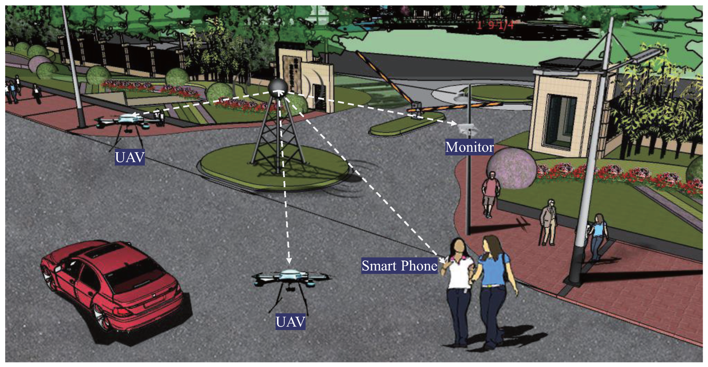
Figure 1. Application scenarios of SWIPT (UAV: unmanned aerial vehicle).
Photonics 13 00659 g001
Figure 2. High-efficiency resonant beam SWIPT system diagram.
Photonics 13 00659 g002
Figure 3. Transmitter structure and operating principles of the semiconductor gain (DBR: distributed Bragg reflector; E g , E gw : energy level difference; L w : quantum well length; h v : photon energy).
Photonics 13 00659 g003
Figure 4. End-to-end energy cycle (I: initial energy density; R 1 , R 2 : reflectivity of M1 and M2; G: gain factor; V: path loss).
Photonics 13 00659 g004
Figure 5. Resonator structure ( d 1 , d 2 , d 3 , l t : element distance; a: radius of gain medium).
Photonics 13 00659 g005
Figure 6. Maximum beam radius on the gain medium as a function of the TIM structure parameter M and transmission distance d 3 : (a) variation with M under different d 3 values; (b) variation with d 3 under different M values.
Photonics 13 00659 g006
Figure 7. Maximum beam radius on the gain versus f r 2 parameters of reflector M2 with different TIM structure parameters.
Photonics 13 00659 g007
Figure 8. Received beam power and conversion efficiency versus thickness of the effective gain layer.
Photonics 13 00659 g008
Figure 9. Received beam power and conversion efficiency versus reflectivity of M2.
Photonics 13 00659 g009
Figure 10. Received beam power and conversion efficiency versus input power.
Photonics 13 00659 g010
Figure 11. Received beam power versus transmission distance.
Photonics 13 00659 g011
Figure 12. Spectral efficiency, output electric power, and end-to-end conversion efficiency versus beam split ratio ( P in = 100 W).
Photonics 13 00659 g012
Figure 13. Spectral efficiency, output electric power, and end-to-end conversion efficiency versus input power ( μ = 0.99).
Photonics 13 00659 g013
Figure 14. Field distribution on the gain medium: (a) without TIM; (b) with TIM.
Photonics 13 00659 g014
Figure 15. Experimental testbed: (a) platform overview, (b) beam output through the reflector M2 (detected by infrared camera), (c) TIM structure, and (d) gain medium and reflector M1.
Photonics 13 00659 g015
Table 1. Parameters of the gain medium [33].
ParameterSymbolValue
Gain factor g 0 2000 cm−1
Transparency carrier density N 0 1.7 × 10 18 cm 3
Longitudinal confinement factor Γ 2.0
Light speedc3 × 108 m/s
Planck constanth 6.6260693 × 10 34 J·s
Monomolecular recombination coefficient α 10 7 s 1
Bimolecular recombination coefficient β 10 10 cm 3 / s
Auger recombination coefficient γ 6 × 10 30 cm 6 / s
Table 2. Comparison of existing SWIPT schemes.
TechnologyRef.Conversion EfficiencySpectral EfficiencyOutput PowerTransmission Distance
Visible light[46] 0.38 × 10 4 % 6 bit/s/Hz2.96 mW1.5 m
[47] 8.44 × 10 5 % 8 bit/s/Hz0.38 mW3.0 m
Radio frequency[48] 1.375 × 10 4 % Not stated 5.5 μ W 15 m
[49] 5 × 10 2 % 7 bit/s/Hz5 mW10 m
Resonant beam[15] 1 % Not stated2 W2.6 m
This work 11 % 18 bit/s/Hz16 W15 m
Disclaimer/Publisher’s Note: The statements, opinions and data contained in all publications are solely those of the individual author(s) and contributor(s) and not of MDPI and/or the editor(s). MDPI and/or the editor(s) disclaim responsibility for any injury to people or property resulting from any ideas, methods, instructions or products referred to in the content.