Article

Hybrid Valley-Polarized Topological Photonic Waveguides for Nonreciprocal Coupling and Configurable Routing

1
National Laboratory of Solid-State Microstructures, School of Physics, Nanjing University, Nanjing 210093, China
2
Collaborative Innovation Center of Advanced Microstructures, Nanjing University, Nanjing 210093, China
*
Author to whom correspondence should be addressed.
Photonics 2026, 13(7), 653; https://doi.org/10.3390/photonics13070653
Submission received: 20 May 2026 / Revised: 19 June 2026 / Accepted: 25 June 2026 / Published: 6 July 2026
(This article belongs to the Special Issue Metasurfaces and Meta-Devices: From Fundamentals to Applications)

Abstract

Topological photonic crystals provide an important platform for robust light transport and light-field manipulation. To meet the demands for developing multifunctional and densely integrated photonic circuits, it is necessary to flexibly control light flow with multi-degrees of freedom while maintaining strong topological protection. In this work, we investigate multifunctional topological photonic crystals based on hybrid topological domain walls, which support valley-polarized chiral edge states (VCES). Based on hybrid domain walls, we design two types of compact topological photonic devices. By exploiting direction-selective coupling between valley edge states (VES) and VCES, we construct nonreciprocal coupled waveguides with a nonreciprocal transmission ratio of 10 dB and output-port isolation ratio of more than 30 dB. Moreover, through different configurations of the direction of external magnetic field, we construct a multi-channel selective routing device that enables the configurable transport of valley-polarized electromagnetic waves among multiple channels. Hybrid topological waveguides provide a foundation for designing novel photonic devices, offering the potential for realizing multifunctional integrated topological photonic networks in both classical and quantum regimes.

1. Introduction

The development of topological photonics has provided new opportunities for manipulating light fields and controlling light–matter interaction, enabling micro- and nanoscale photonic devices with enhanced robustness and flexible tunability [1,2,3,4,5,6,7,8,9,10,11]. For example, photonic Chern insulators with broken time-reversal symmetry can emulate the quantum anomalous Hall effect and support chiral edge states [11,12,13,14,15,16,17,18,19,20,21,22,23]. For time-reversal invariant photonic topological insulators, crystalline symmetry gives rise to analogues of the quantum spin Hall and quantum valley Hall effects, which are characterized by pseudospin-momentum locked edge states [24,25,26,27,28,29] and valley-momentum locked edge states [30,31,32,33,34,35,36], respectively. By extending dimensions of topological effects, higher-order topological insulators can be explored, characterized by localized corner states [37,38,39,40]. Meanwhile, richer topological phenomena can be implemented in three-dimensional [41,42,43] and synthetic-dimensional systems [44,45,46].
Based on these topological effects, a range of integrated topological photonic devices have been proposed, including topological lasers [47,48], optical beam splitters [49,50], optical cavities [51,52], and logic devices [53,54]. These devices mainly rely on edge and corner states protected by topological invariants. However, to meet the demands of multifunctionality and dense integration in optical information processing, it is necessary not only to ensure the stable propagation of topological edge states and their robustness against fabrication defects and disorder, but also to achieve more flexible and sophisticated control of these states across multiple degrees of freedom. Systems with broken time-reversal symmetry exhibit nonreciprocity. When the bandgap of the designed structure has a nonzero Chern number, the corresponding edge states are strongly topologically protected, overcoming the limitation of relatively weaker protection of valley edge states [55,56,57]. Such systems offer distinct advantages for constructing nonreciprocal waveguide couplers, isolators and multi-channel routers, providing a route toward compact topological waveguide interconnects and complex functional devices.
Compared with a single type of topological structure, hybrid topological structures can support multiple types of topological states and allow phase transitions between different topological states through parameter tuning [58,59], which enrich the physical properties of topological domain walls, increase the number of topological channels and enable more diverse functionalities [60]. A recent study has shown that a hybrid topological domain wall formed by interfacing a Chern-type lattice with a valley-type lattice can support chiral edge states with valley polarization, thereby combining the advantages of both states [61]. In addition, the valley polarization of chiral edge states can also be manipulated by boundary engineering [62].
Here, we exploit the properties of valley-polarized chiral edge states supported by hybrid topological domain walls to construct nonreciprocal topological waveguides. The lattices on the two sides of the domain wall break time-reversal symmetry and parity symmetry, respectively. The resulting hybrid domain wall supports chiral edge states with both a nonzero Chern number and valley polarization. Based on this platform, we design nonreciprocal topological photonic devices. A coupled waveguide system formed by VES and VCES exhibits a nonreciprocal transmission ratio of 10 dB and an output-port isolation ratio exceeding 30 dB. To meet the requirements of multi-channel routing and channel selection, we further demonstrate that the VCES can be guided along selected paths to different channels under four configurations of magnetic field. Our work demonstrates the potential of hybrid topological structures for on-chip nonreciprocal devices and provides a perspective for developing multifunctional and highly integrated topological photonic devices.

2. Hybrid Valley-Polarized Topological Domain Walls

In this work, we consider a two-dimensional photonic crystal system composed of periodically arranged cylindrical microstructures made of either dielectric or gyromagnetic materials in air, focusing on TM-polarized electromagnetic waves. A honeycomb lattice with C 6 v symmetry hosts paired Dirac points at the K and K valleys of the Brillouin zone, which are protected by both time-reversal symmetry ( T Symmetry) and parity symmetry ( P Symmetry). We lift the degeneracy of the Dirac points in two different ways and investigate the nontrivial topological properties of the opened bandgaps. The lattice constant of the honeycomb lattice discussed in this article is a = 11.7   m m .
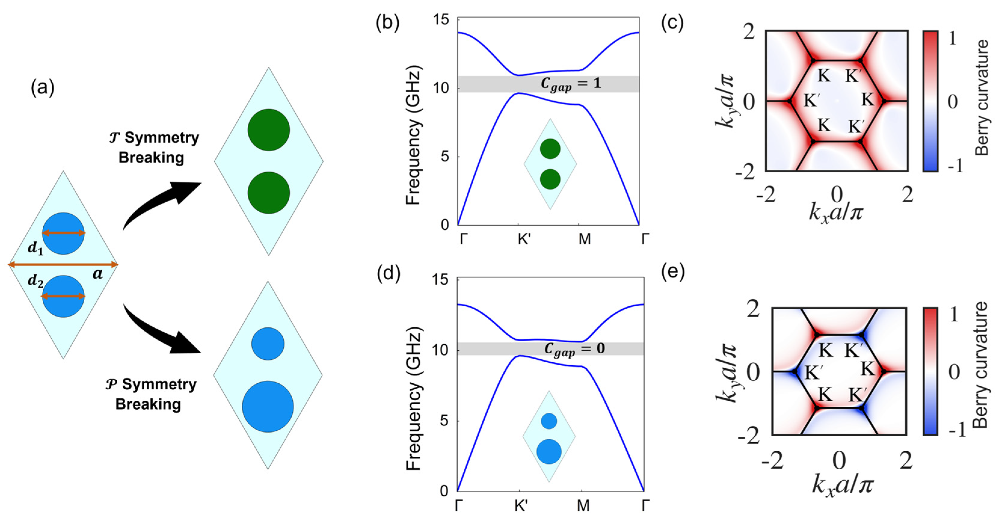
As shown in Figure 1a, the unit cell can be demonstrated as a parallelogram containing two sites. The first approach is to break T symmetry by exploiting the nonreciprocal response of the gyromagnetic material YIG under an external magnetic field, while keeping the diameters of the gyromagnetic cylinders at the two neighboring sites of the unit cell identical, d 1 = d 2 = 2.93   m m . The permittivity of the gyromagnetic material is ε 1 = 14.6 , and its permeability tensor is given by
μ 1 = μ r i μ k 0 i μ k μ r 0 0 0 1
where μ r = 1 +   ω 0 + i α ω ω m ω 0 + i α ω 2 ω 2 , μ k = ω ω m ω 0 + i α ω 2 ω 2 , ω m = 4 π γ M s , ω 0 = γ μ 0 H 0 . The saturation magnetization is 4 π M s = 1950 Gauss, the gyromagnetic ratio is γ = 17.6 MHz/Oe, the damping coefficient is α = 0.0001 , and the external magnetic field is applied along the z -direction with a magnitude of H 0 = 700 Oe. The angular frequency of the operating light field is ω . Although the permeability is in principle frequency-dependent, the bandgap studied in this work is located around 10 GHz, where the permeability varies slowly with frequency. Therefore, it can be treated as a frequency-independent value in the following calculations.
The unit cells with magnetic fields applied along the positive and negative z -directions are denoted as M1 and M2, respectively. Taking the M1 unit cell as an example, the calculated eigenfrequency band structure is shown in Figure 1b, where a bandgap opens at the K point. We then calculate the Berry curvature and Chern number of the first band below the bandgap. The Berry curvature is defined as
Ω n k = k × i   u n , k k | u n , k
where u n , k is the periodic part of the Bloch wave function in real space. The Chern number is obtained by integrating the Berry curvature over the entire Brillouin zone, the hexagonal region in Figure 1c:
C n = 1 2 π Ω n k d 2 k
As shown in Figure 1c, the Berry curvature of the M1 unit cell is positive in the whole Brillouin zone, giving a Chern number of + 1 for the band below the bandgap. For the M2 unit cell with the opposite magnetic-field direction, both the Berry curvature distribution and the Chern number are reversed. According to the bulk-boundary correspondence, one chiral edge state emerges at the interface between a topologically nontrivial structure with Chern number of ± 1 and a trivial structure with Chern number of 0 . As a topological invariant, Chern number provides strong topological protection for the edge state.
The second approach is to break P symmetry, reducing C 6 v symmetry to C 3 v symmetry. In this case, dielectric ceramic cylinders are used, and the diameters of the cylinders at neighboring sites of the unit cell are made unequal, namely d 1 = 3.38 m m , d 2 = 2.73   m m . The dielectric material has a permittivity of ε 2 = 8.8 and a permeability of μ 2 = 1 . The two unit cells with d 1 > d 2 and d 1 < d 2 are denoted as V1 and V2, respectively. A bandgap can also be opened at K point in these structures. By carefully tuning the structural parameters, the bandgap range is adjusted to approximately overlap with those of M1 and M2. The calculated Berry curvature has opposite signs near K and K valleys. Integrating Berry curvature over the Brillouin zone gives a Chern number of 0 for the band below the bandgap, as shown in Figure 1d,e. On the other hand, valley edge states (VES) can emerge at the interface between V1 and V2, whose different geometric structures lead to opposite signs of Berry curvature in the vicinity of both K and K valleys and therefore an opposite valley Chern number. These edge states exhibit valley-polarized characteristics with opposite group velocities. However, since the valley Chern number is not a topological invariant defined over the entire Brillouin zone, the corresponding topological protection is relatively weak. As a result, valley edge states are more sensitive to geometric details, which may lead to band deformation and backscattering at the boundary.
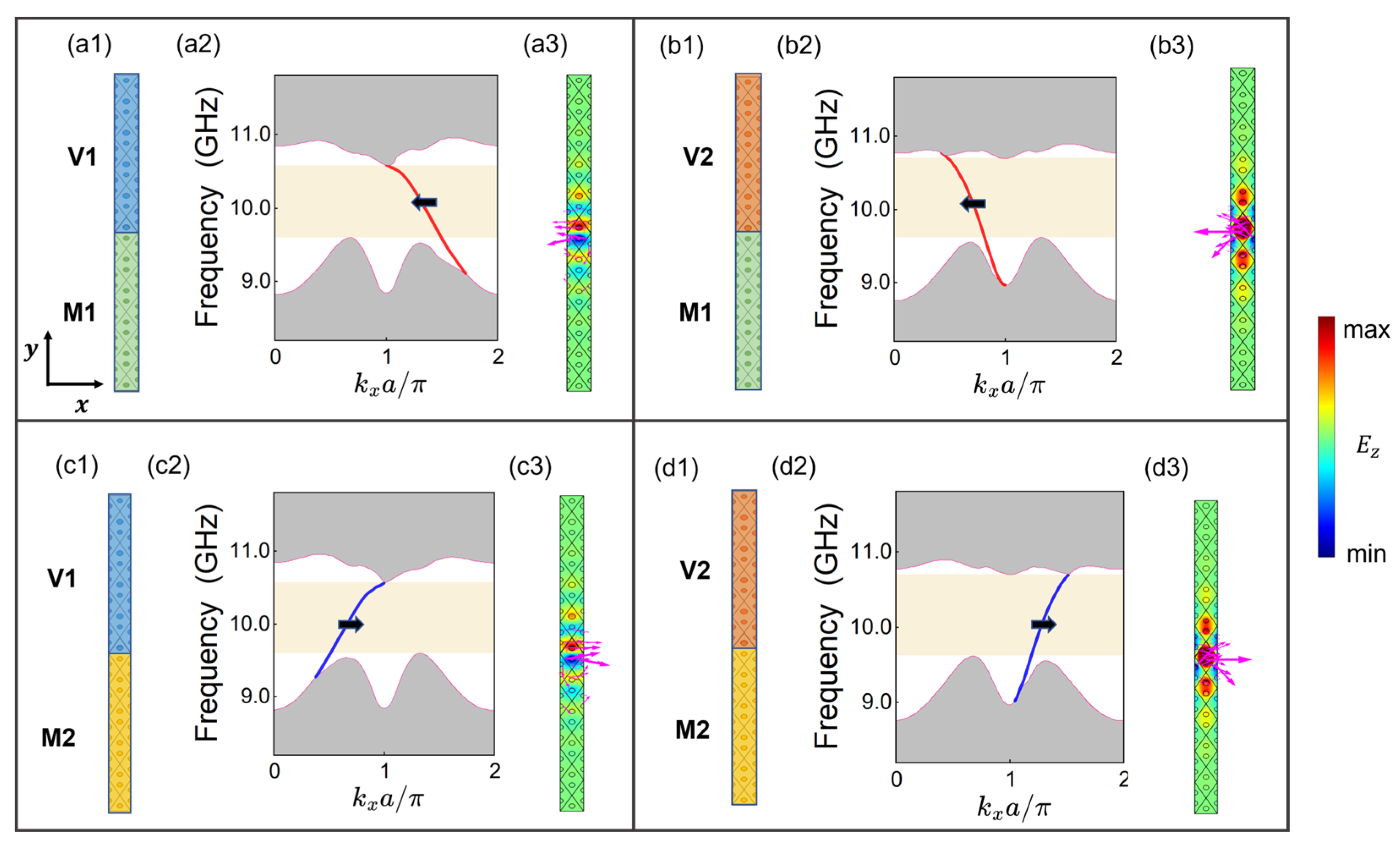
Based on the topological protection principles of the two types of topological edge states above, we construct a hybrid topological domain wall that combines their advantages altogether. Taking Figure 2(a1) as an example, an external magnetic field of H 0 = 700 Oe is applied along the positive z -direction. The M1 unit cell composed of gyromagnetic material YIG and the V1 unit cell composed of dielectric material are interfaced to form a ribbon-shaped supercell, which is periodic along the x -direction and finite along the y -direction. The supercell contains 6 M1 unit cells and 6 V1 unit cells. The corresponding projected band structure is shown in Figure 2(a2). A hybrid edge state fully traverses the bandgap, connecting the lower and upper bulk bands, and exhibits an approximately linear dispersion near the center of the bandgap around 10 GHz. According to the band topology analysis in Figure 1, the existence of this boundary state is consistent with the bulk-boundary correspondence. It is protected by a Chern number of + 1 , and therefore crosses the entire bandgap in a manner similar to the edge state in the quantum Hall effect. On the other hand, the edge state is endowed with a valley-polarized characteristic, with the corresponding wave vector mainly concentrated near K valley 4 π 3 a , 0 . Since K and K valleys are well separated in the Brillouin zone, intervalley scattering is nearly suppressed. Therefore, an additional valley degree of freedom is introduced for chiral edge states, leading to the emergence of VCES. The distributions of the electric field E z and the surface energy flux density in Figure 2(a3) show that the VCES is localized near the hybrid topological domain wall and exhibits leftward unidirectional propagation.
Similarly, when unit cell M1 and V2 are arranged on the hybrid domain wall, as shown in Figure 2(b1,b3), the Chern number remains + 1 . The change on the valley polarization property of the unit cell leads to localization of the edge state near K valley 2 π 3 a , 0 . When the external magnetic field is reversed, namely when unit cell M2 is used to construct the hybrid topological domain wall, the Chern number becomes 1 . As a result, the group velocity of the edge state is reversed, while the state still exhibits a valley-polarized characteristic. The VCES propagates unidirectionally to the right, as shown in Figure 2(c1–c3,d1–d3). These results show that, although the hybrid topological domain wall constructed here does not increase the number of boundary states or induce phase transitions between different topological states, it enables the control of valley polarization while preserving the strong topological protection of chiral edge states, providing opportunity for designing robust valley-polarized devices.

3. Nonreciprocal Waveguide Coupling Based on Hybrid Valley-Polarized Topological Domain Walls

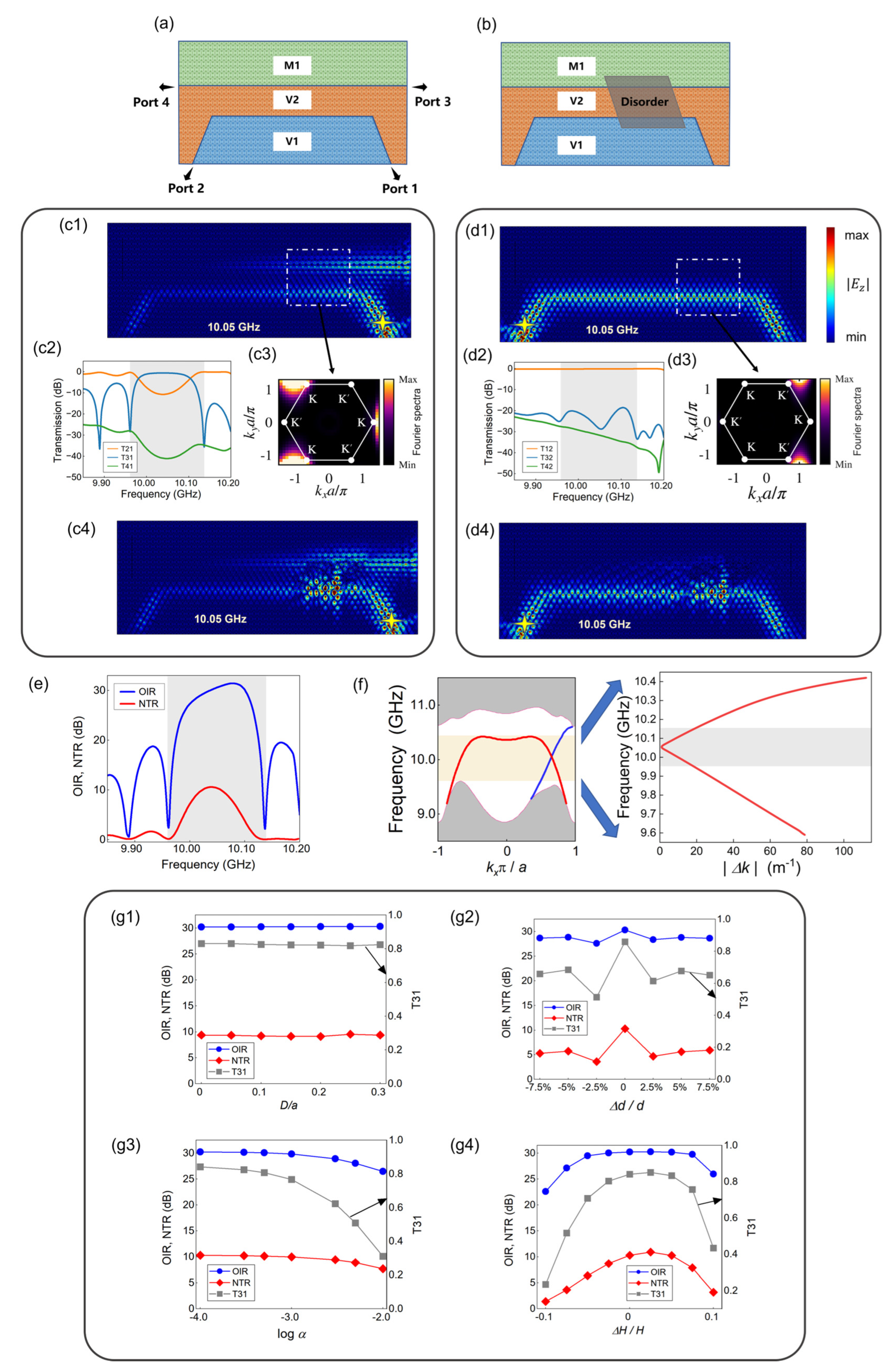
Large-scale compact photonic circuits require efficient coupling between waveguides. Recent work has used VES in topological photonic crystals to realize valley-conserved tunable coupling in the terahertz regime. However, the reciprocal nature of VES limits their use in nonreciprocal waveguide coupling and high-isolation devices. Based on the hybrid valley-polarized topological domain wall, we exploit the nonreciprocal response of YIG under an external magnetic field to construct a waveguide system with nonreciprocal coupling between VES and VCES, as shown in Figure 3a. The interface between the V1 and V2 lattices supports reciprocal VES, which can be excited from either port 1 or port 2 by a phase-vortex current source. The hybrid domain wall between the M1 and V2 lattices supports nonreciprocal VCES, which can propagate from port 4 to port 3.
When a K -valley edge state is excited at port 1 using a “right-handed” phase-vortex current source, valley-conserved coupling occurs in the central region between the two waveguides. A pronounced output is observed at port 3 of the hybrid domain wall, while the output at port 4 is nearly negligible, as shown in Figure 3(c1). The calculated port transmittance shows that, at 10.05 GHz, the coupled output at port 3 and the directly transmitted output at port 2 exhibit a transmission contrast of approximately 10 dB, as shown in Figure 3(c2). Furthermore, a two-dimensional Fourier transform of the electric field inside the white dashed box gives the Fourier spectrum, which confirms that the coupling process preserves the valley polarization. The output VCES also exhibits K valley polarization, as shown in Figure 3(c3). In contrast, when a K valley edge state is excited from port 2 by a “left-handed” phase-vortex current source, waveguide coupling is almost negligible. The valley edge state is transmitted to port 1 with little coupling loss, while the transmission at the other ports remains generally below 20 dB, as shown in Figure 3(d1,d2). The Fourier transform of the electric field inside the white dashed box further verifies the K valley-polarized characteristic, as shown in Figure 3(d3).
To quantitatively evaluate the nonreciprocal coupling performance, we calculate the nonreciprocal transmission ratio (NTR) between ports 1 and 2 of the valley waveguide and the output isolation ratio (OIR) between the output ports of the hybrid waveguide. They are defined as
N T R = 10 log 10 T 21 T 12
O I R = 10 log 10 T 31 + T 32 T 41 + T 42
where T 21 , T 31 , and T 41 denote the transmittances at the corresponding output ports when port 1 is excited, while T 12 , T 32 , and T 42 denote those when port 2 is excited. As shown in Figure 3e, both the NTR and OIR remain high in the middle of the bandgap from 10.0 to 10.1 GHz. The maximum NTR is approximately 10 dB, indicating that the originally reciprocal VES exhibits pronounced nonreciprocal transmission under the influence of the nonreciprocal structure. In other words, the coupling efficiencies of the K and K valley edge states into the hybrid waveguide differ significantly. The maximum OIR is approximately 30 dB at the frequency of 10.05 GHz, showing that the output ports of the hybrid waveguide provide strong isolation for waveguide coupling from opposite directions. Together, these results demonstrate a clear nonreciprocal coupling effect in this system, indicating that the proposed structure can serve as an efficient isolation element for compact topological photonic circuits.
It is necessary to point out that although the common bulk bandgap of VES and VCES is relatively broad (9.6–10.5 GHz), the operational bandwidth of the nonreciprocal coupling device is narrower (approximately 10.0–10.1 GHz). The device performance is governed not only by the frequency range of edge states, but also by the phase-matched coupling between VES and VCES. Efficient coupling requires valley conservation, propagation-direction matching, sufficient modal overlap, and small longitude momentum mismatch between the two modes. To verify this point, we calculate the projected bands of the VES and VCES (Figure 3f, left panel) and extract the frequency-dependent momentum mismatch k =   k V E S k V C E S near the same valley (Figure 3f, right panel). The two edge modes are nearly phase matched around 10.05 GHz, where k reaches its minimum. The frequency range in which k remains small agrees well with the observed high-performance window of approximately 10.0–10.1 GHz. This result indicates that the narrower operational bandwidth originates mainly from the requirement of momentum matching of the coupling structure, rather than from the width limitation of the bulk bandgap.
This interpretation can be understood from coupled-mode theory. If the VES and VCES amplitudes are denoted by a 1 and a 2 propagating along x direction, their coupling is described by the following spatial coupled-mode equations:
d a 1 d x = i κ a 2 e i Δ β x
d a 2 d x = i κ a 1 e i Δ β x
in which Δ β = β 1 β 2 is the mismatch of the propagation constant of the two modes and κ is the coupling coefficient determined by the modal overlap. Therefore, the coupled power P V C E S from the excited VES to the VCES in the hybrid domain wall can be obtained in this theoretical model,
P V C E S = κ 2 κ 2 + ( Δ β / 2 ) 2 s i n 2 L κ 2 + ( Δ β / 2 ) 2 .
Equation (8) indicates that efficient VES–VCES coupling requires both a sufficiently large coupling coefficient κ and a small phase mismatch Δ β . When the frequency moves away from the phase-matching point, Δ β increases and the maximum transferable power is reduced, which is consistent with the results of full-wave simulation. The finite-length interference also leads to the oscillatory frequency dependence of OIR in Figure 3e.
To further clarify the practical significance of the achieved bandwidth, we compare the present device with representative valley–photonic–crystal couplers and gyromagnetic nonreciprocal coupling devices, as summarized in Table 1.
The comparison shows that valley topological couplers can provide broader reciprocal operating bandwidths, especially at telecommunication wavelengths. However, these devices are generally reciprocal and do not provide magnetic nonreciprocal transmission or output-port isolation. In contrast, gyromagnetic one-way waveguides and circulators provide nonreciprocal transport, but they generally do not exploit valley-polarized coupling. The present device therefore performs a more sophisticated function: it requires phase-matched VES–VCES coupling while simultaneously maintaining valley polarization and magnetic nonreciprocity. Although the high-performance window of approximately 0.1 GHz is narrower than the bulk topological bandgap and narrower than some broadband reciprocal valley–Hall couplers, it is practically meaningful because it is achieved together with NTR of about 10 dB, OIR of about 30 dB, and robust valley-preserved coupling.
These results suggest several possible strategies for improving the operational bandwidth. First, the coupling coefficient κ can be adjusted by changing the waveguide separation and the geometry of the coupling region, which can increase the tolerance to phase mismatch. Second, the coupling length L should be optimized to balance high peak coupling efficiency and broad bandwidth. Finally, a tapered or adiabatic coupling region may reduce abrupt mode mismatch and finite-size interference, leading to a smoother frequency response. These structural optimizations could further broaden the operational bandwidth while maintaining the nonreciprocal and valley-selective coupling characteristics.
To demonstrate the robustness of the nonreciprocal coupling device, we introduce a disordered region in the coupling area between the two waveguides, as shown in Figure 3b. In the first case, the positions of cylinders in the disordered region are randomly perturbed according to
x i = x i 0 + D ξ x i
y i = y i 0 + D ξ y i
where x i and y i are the coordinates after disorder is introduced, x i 0 and y i 0 are the original coordinates, D is the disorder strength, and ξ x i and ξ y i are random numbers uniformly distributed in the range 0.5 ,   0.5 . When the disorder strength reaches D = 0.3 a , the electric-field distributions for excitation from ports 1 and 2 are shown in Figure 3(c4,d4), respectively. Although the disordered region causes noticeable scattering, the nonreciprocal coupling effect remains distinct. As shown in Figure 3(g1), at a fixed frequency of 10.05 GHz, both the NTR and OIR change only slightly as the disorder strength increases, and the transmittance T 31 maintains a high value above 80%.
To further examine the robustness of the device, we evaluate the influence of three additional perturbations relevant to realistic implementations, including the perturbation of cylinder diameters, YIG material loss, and magnetic field fluctuation. The results are demonstrated in Figure 3(g2–g4). All quantities were calculated at the operating frequency of 10.05 GHz. For the diameter perturbation, the cylinder diameters are varied with a relative perturbation strength d / d up to ± 7.5 % , as shown in Figure 3(g2). The NTR and OIR remain above 4 dB and 27 dB, respectively, while T 31 varies around 60%. The results in Figure 3(g1,g2) indicate that the nonreciprocal coupling is not restricted to an ideal geometric parameter set and has relatively high fabrication tolerance. For the YIG loss, the damping coefficient α is increased from the baseline value of 1 × 10 4 to a high value of 1 × 10 2 , as shown in Figure 3(g3). Increasing α mainly introduces additional absorption and reduces the output transmittance T 31 , whereas the isolation ratio remains largely preserved within the practical loss range. For the magnetic field fluctuation, the strength of the bias magnetic field is varied as H / H up to ± 10 % , while its direction is kept unchanged. As shown in Figure 3(g4), moderate magnetic-field variations only weakly affect the NTR, OIR and T 31 . This is because such fluctuations mainly induce a small detuning of the gyromagnetic permeability, therefore a slight shift of bandgap and phase matching point, rather than destroying the chiral edge channel. These results show that the proposed nonreciprocal waveguide coupler has strong topological protection and maintains its direction-selective coupling and output isolation under moderate perturbations, exceeding that of ordinary valley waveguides.

4. Multi-Channel Robust Routing Based on Configurable Hybrid Valley-Polarized Domain Walls

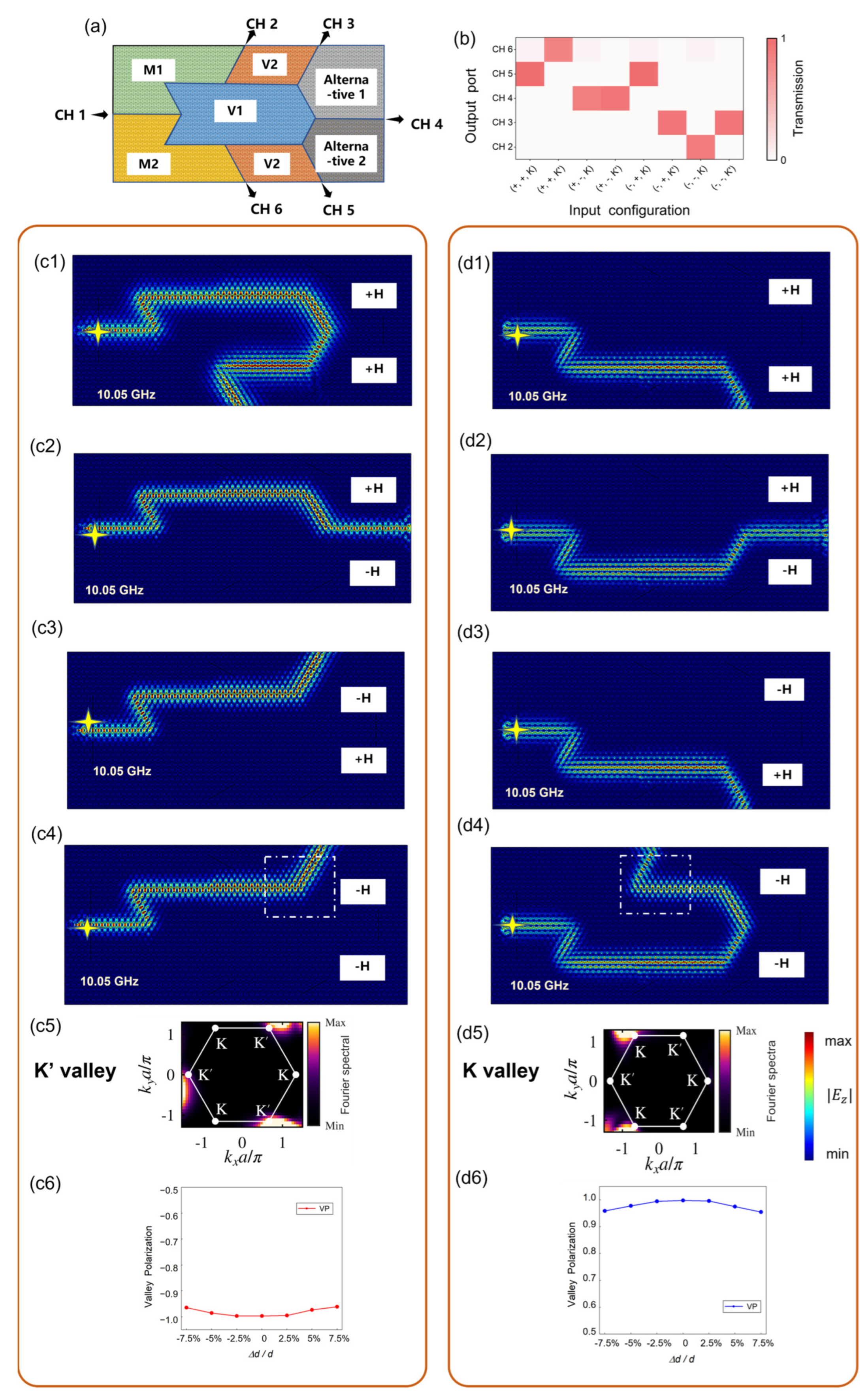
For photonic waveguide networks, robust multi-channel routing is another important function. By configuring the directions of the external magnetic fields, the strongly protected and valley-polarized edge states supported by the hybrid topological domain walls can be selectively guided into different channels, providing an opportunity for designing functional devices such as logic gates and optical switches. As shown in Figure 4a, valley-polarized electromagnetic waves incident from channel 1 (CH 1) can be routed to channels 2–6 (CH 2–CH 6). “Alternative 1” and “Alternative 2” denote the regions with preset configurable magnetic field directions. A magnetic field of + H along the positive z direction corresponds to the M1 lattice in Figure 2, while a magnetic field of H along the negative z direction corresponds to the M2 lattice. In both cases, the field magnitude is H 0 = 700 Oe. Since the M1 and M2 lattices have Chern numbers of + 1 and 1 , respectively, their interface supports two co-propagating chiral edge states located near K and K valleys, respectively. Each state can be selectively excited by a valley-polarized vortex current source. The V1 and V2 lattices both have Chern numbers of 0 but opposite valley polarization, so their interface supports two counter-propagating VES located near K and K valleys, respectively. In this multi-channel structure, topological edge states can propagate through channels that satisfy both propagation direction matching and valley matching.
For the eight combinations formed by four magnetic field configurations and two valley-polarized incident waves, we calculate the transmittance of CH 2–CH 6 at 10.05 GHz. The resulting output port transmission distribution is shown in Figure 4b. Here, + , , K denotes the case in which the “Alternative 1” region is under a + H magnetic field, the “Alternative 2” region is under a H magnetic field, and the incident wave is K valley polarized. The other labels are defined in the same way. Figure 4(c1–c4,d1–d4) show the electric-field distributions for K and K valley-polarized edge states in different channels, respectively. The K valley-polarized edge states can be routed to CH 3, CH 4, and CH 6, while the K valley-polarized edge states can be routed to CH 2, CH 4, and CH 5.
A two-dimensional Fourier transform of the electric field in the white dashed box, shown in Figure 4(c5,d5), confirms the valley-polarized nature of the topological edge states supported by the multi-channel routing structure. To provide a more quantitative evaluation of valley preservation, we further calculate the spectral weights around the two inequivalent valleys. The complex electric field E z ( x , y ) in the dashed box is Fourier transformed as E z ( k x , k y ) . The valley concentration is then obtained by integrating E z ( k x , k y ) within circular windows Ω K ( K ) centered at the K and K valleys:
P K ( K ) = | E ~ z ( k x , k y ) | 2 d k x d k y
Hence, the valley polarization (VP) can be defined as:
V P = P K P K P K + P K .
For the nonreciprocal coupled-waveguide structure in Figure 3, the Fourier space integration gives V P = 0.998 for K valley excitation from port 2 and V P = 0.993 for K valley excitation from port 1 at f = 10.05   G H z . We further calculated V P at the moderate perturbation strength considered in each robustness test in Figure 3(g1–g4). For cylinder position disorder with D = 0.1 a , the calculated values are V P = 0.763 for K -valley excitation and V P = −0.864 for K -valley excitation. For cylinder diameter perturbation with d / d = 7.5 % , the corresponding values are V P = 0.955 and V P = 0.961 . For YIG material loss with α = 10 2 , the values are V P = 0.996 and V P = 0.997 . For magnetic-field fluctuation with H / H = 10 % , the values are V P = 0.992 and V P = 0.996 . In all these cases, the sign of V P remains unchanged and the absolute value remains large. These results indicate that the considered perturbations may affect the transmission amplitude and phase-matching condition, but they do not induce significant intervalley conversion. Therefore, the robustness of NTR, OIR, and T 31 is accompanied by the preservation of the valley-polarized degree of freedom.
For the multi-channel routing structure in Figure 4, the same Fourier-space integration was applied to all eight configurations. Across all configurations, the absolute value of valley polarization remains above 0.995. We select two representative routing configurations for K -valley and K -valley excitations and introduce cylinder diameter perturbation into the selected white dashed box in Figure 4(c5,d5). The perturbation strength was described by the same relative parameter d / d as used in Figure 3(g2). The calculated dependence of V P on perturbation is shown in Figure 4(c6,d6), respectively. For both the K -valley and K -valley routing case, the absolute value of V P remains large. These results show that the dominant spectral weight remains concentrated in the target valley after propagation and coupling, while the intervalley scattering is strongly suppressed even in the presence of moderate disorder.
In addition, we evaluate the backscattering of the valley-polarized edge states. In Figure 3(c2,d2), the total transmission of T 21 , T 31 , and T 41 is above 95%, which means the remaining uncollected power, including possible reflection, radiation leakage, and material absorption, is less than 5%. Together with the large VP values, this confirms that the coupled waveguide structure suppresses intervalley scattering while maintaining efficient nonreciprocal transport. In Figure 4, the input reflection is evaluated from the port reflection coefficient R 11 and all eight configurations show reflection below 0.8%, indicating that the backscattering of routing process is almost negligible.
It should be noted that the magnetic-field configuration considered here is quasi-static. In the present proof-of-concept design, the routing state is selected by presetting the magnetic field directions in the two configurable regions “Alternative 1” and “Alternative 2” before operation. The response time of the routing reconfiguration is not determined by the topological edge-state propagation itself, but by the external magnetic-bias implementation. Considering the experimental implementation, if the bias field is provided by manually positioned permanent magnets, the configuration can be changed only in a slow, quasi-static manner. For future practical implementations, electrical control of the local bias magnetic field using integrated coils, current lines, or other magnetization-control schemes could enable more convenient and faster reconfiguration. Meanwhile, such implementations would require the additional consideration of magnetic field localization, crosstalk, Joule heating and compatibility with the photonic crystal platform. In integrated platforms, the two configurable regions should be independently tunable while maintaining sufficiently uniform out-of-plane magnetic bias fields and suppressing stray fields near adjacent channels. Nonuniform magnetization, thermal drift from current-driven elements, or fabrication induced deviations at the gyromagnetic interface may shift the edge state dispersion and the valley or phase matching condition, thereby reducing the routing contrast. Therefore, future experimental implementations should combine low-loss gyromagnetic material integration, localized magnetic-bias engineering, and thermal or electrical isolation.
Overall, this configurable multi-channel router combines the valley degree of freedom with magnetic-field configuration, demonstrating the potential of hybrid topological waveguides for large-scale optical interconnects and functional photonic devices.

5. Discussion

In this work, we have investigated a functional device platform based on hybrid valley-polarized topological waveguides. By interfacing gyromagnetic unit cells with broken T symmetry and dielectric valley unit cells with broken P symmetry, we construct a hybrid topological domain wall supporting VCESs, which are strongly topologically protected and exhibit valley-polarized characteristics at the same time.
In response to the need for flexible control of topological edge states in integrated photonic circuits, we design two types of robust topological photonic devices. The first is a nonreciprocal coupling device composed of a valley waveguide and a hybrid waveguide, which exhibits distinct nonreciprocal transmission, direction-selective coupling and output isolation. The second is a multi-channel selective router with configurable magnetic field directions, which enables selective port distribution of valley-polarized electromagnetic waves. Hybrid valley-polarized topological photonic crystals therefore provide a flexible and multifunctional platform, offering a design route for topological photonic interconnects, large-scale integrated topological photonic circuits, and complex waveguide networks.
Furthermore, the hybrid topological platform also exhibits potential application in many aspects, such as constructing non-Hermitian photonic devices, realizing high-Q resonance modes and manipulating micro-particles through optical force [67,68,69,70,71,72,73,74,75]. The development of more flexible experimental control schemes and scalable fabrication techniques may enable the large-scale integration of hybrid valley-polarized topological structures, opening new possibilities for advanced light-field manipulation in both classical and quantum photonic systems.

Author Contributions

Conceptualization, J.H. and S.W.; methodology, J.H. and S.W.; software, J.H.; validation, G.G. and S.W.; formal analysis, J.H.; investigation, J.H.; resources, S.W.; data curation, J.H.; writing—original draft preparation, J.H.; writing—review and editing, G.G., H.L., T.S., Z.W., G.L. and S.W.; visualization, J.H.; supervision, S.W.; project administration, S.W.; funding acquisition, S.W. All authors have read and agreed to the published version of the manuscript.

Funding

This work was supported by National Program on Key Basic Research Project of China (2023YFF0713302, 2024YFB3815900, 2022YFA1404300), National Natural Science Foundation of China (No. 12325411, 62288101), Jiangsu Provincial Key Research and Development Program (BG2024029), Fundamental and Interdisciplinary Disciplines Breakthrough Plan of the Ministry of Education of China (JYB2025XDXM106), Fundamental Research Funds for the Central Universities (KG202513).

Institutional Review Board Statement

Not applicable.

Informed Consent Statement

Not applicable.

Data Availability Statement

The data that support the findings of this article is available upon reasonable request.

Conflicts of Interest

The authors declare no conflicts of interest.

Abbreviations

The following abbreviations are used in this manuscript:
VCESValley-polarized chiral edge state
VESValley edge state
NTRNonreciprocal transmission ratio
OIROutput isolation ratio
CH 1Channel 1
VPValley polarization

References

  1. Lu, L.; Joannopoulos, J.D.; Soljačić, M. Topological photonics. Nat. Photonics 2014, 8, 821–829. [Google Scholar] [CrossRef]
  2. Ozawa, T.; Price, H.M.; Amo, A.; Goldman, N.; Hafezi, M.; Lu, L.; Rechtsman, M.C.; Schuster, D.; Simon, J.; Zilberberg, O.; et al. Topological photonics. Rev. Mod. Phys. 2019, 91, 015006. [Google Scholar] [CrossRef]
  3. Wang, G.; Lu, L. Topological microwave isolator with >100-dB isolation. Nat. Photonics 2025, 19, 1064–1069. [Google Scholar] [CrossRef]
  4. Jia, R.; Wang, W.; Tan, Y.J.; Shen, Z.; Tan, T.C.; Gu, Z.; Pitchappa, P.; Singh, R. On-Chip Active Supercoupled Topological Cavity. Adv. Mater. 2025, 37, 2419261. [Google Scholar] [CrossRef] [PubMed]
  5. Li, T.; Gao, W.; Fu, B. Scalable generalized meta-spanners enabling parallel multitasking optical manipulation. Sci. Adv. 2026, 12, eaed5302. [Google Scholar] [CrossRef] [PubMed]
  6. Li, T.; Liu, M.; Hou, J.; Yang, X.; Wang, S.; Wang, S.; Zhu, S.; Tsai, D.P.; Wang, Z. Chip-scale metaphotonic singularities: Topological, dynamical, and practical aspects. Chip 2024, 3, 100109. [Google Scholar] [CrossRef]
  7. Lu, C.-C.; Yuan, H.-Y.; Zhang, H.-Y.; Zhao, W.; Zhang, N.-E.; Zheng, Y.-J.; Elshahat, S.; Liu, Y.-C. On-chip topological nanophotonic devices. Chip 2022, 1, 100025. [Google Scholar] [CrossRef]
  8. Wang, H.; Sun, L.; Li, J.; Wang, Z.; Pu, Z.; He, Y.; Zhang, Y.; Hu, X.; Yuan, L.; Dong, J.; et al. Refraction and Coupling of Topological Edge State Based on Silicon Valley Photonic Crystals. Laser Photonics Rev. 2025, 19, 2401627. [Google Scholar] [CrossRef]
  9. Wang, W.; Tan, Y.J.; Szriftgiser, P.; Ducournau, G.; Singh, R. On-chip topological leaky-wave antenna for full-space terahertz wireless connectivity. Nat. Photonics 2026, 20, 317–323. [Google Scholar] [CrossRef]
  10. Zhang, J.C.; Tsai, D.P.; Pang, S.W. Non-local bound states in the continuum for nanoscale alignment. Nat. Photonics 2026, 20, 296–300. [Google Scholar] [CrossRef]
  11. Zhang, X.; Li, S.; Lan, Z.; Gao, W.; Chen, M.L.N. Reconfigurable Photonic Valley Filter in Hybrid Topological Heterostructures. Laser Photonics Rev. 2024, 19, 2400797. [Google Scholar] [CrossRef]
  12. Haldane, F.D.M. Model for a Quantum Hall Effect without Landau Levels: Condensed-Matter Realization of the “Parity Anomaly”. Phys. Rev. Lett. 1988, 61, 2015–2018. [Google Scholar] [CrossRef] [PubMed]
  13. Wang, Z.; Chong, Y.D.; Joannopoulos, J.D.; Soljačić, M. Reflection-Free One-Way Edge Modes in a Gyromagnetic Photonic Crystal. Phys. Rev. Lett. 2008, 100, 013905. [Google Scholar] [CrossRef] [PubMed]
  14. Wang, Z.; Chong, Y.; Joannopoulos, J.D.; Soljačić, M. Observation of unidirectional backscattering-immune topological electromagnetic states. Nature 2009, 461, 772–775. [Google Scholar] [CrossRef] [PubMed]
  15. Sun, X.-C.; He, C.; Liu, X.-P.; Zou, Y.; Lu, M.-H.; Hu, X.; Chen, Y.-F. Photonic Topological States in a Two-Dimensional Gyrotropic Photonic Crystal. Crystals 2019, 9, 137. [Google Scholar] [CrossRef]
  16. Jing, Y.; Yang, Y.; Long, W.; Zhang, T.; Wu, D.; Wang, J.; Xiong, Z.; Chen, N.; Wang, M.; Chan, C.T.; et al. Experimental Realization of Highly Efficient Beam Combination and Steering via Topological Multimode. Laser Photonics Rev. 2025, 19, 2401157. [Google Scholar] [CrossRef]
  17. Wu, Z.; Wang, Z.; Meng, Y.; Chen, J.; Xi, X.; Shum, P.P.; Gao, Z. Realization of a Chiral Topological Whispering-Gallery-Mode Cavity in Gyromagnetic Photonic Crystals. Laser Photonics Rev. 2024, 19, 2401451. [Google Scholar] [CrossRef]
  18. Xu, M.; Liang, C.; Liu, J.; Gong, Z.; Fan, L.; Zhong, J.; Liang, L.; Poo, Y. Realization of a Magnetically Tunable Slow Light Waveguide Based on Topological Modes Coupling. Laser Photonics Rev. 2026, 20, e02921. [Google Scholar] [CrossRef]
  19. Liu, S.; Yang, Y.; Shi, L.; Wang, E.; Hang, Z.H. Chiral and Antichiral Edge States in Gyromagnetic Photonic Crystals under Magnetic and Pseudomagnetic Fields. Photonics Res. 2025, 13, 2688–2696. [Google Scholar] [CrossRef]
  20. Chen, J.; Li, Z.Y. Prediction and Observation of Robust One-Way Bulk States in a Gyromagnetic Photonic Crystal. Phys. Rev. Lett. 2022, 128, 257401. [Google Scholar] [CrossRef] [PubMed]
  21. Chen, J.; Zheng, Y.; Yang, S.; Alu, A.; Li, Z.Y.; Qiu, C.W. Chern-Protected Flatband Edge State in Metaphotonics. Phys. Rev. Lett. 2025, 134, 223806. [Google Scholar] [CrossRef] [PubMed]
  22. Zhou, P.; Liu, G.G.; Yang, Y.; Hu, Y.H.; Ma, S.; Xue, H.; Wang, Q.; Deng, L.; Zhang, B. Observation of Photonic Antichiral Edge States. Phys. Rev. Lett. 2020, 125, 263603. [Google Scholar] [CrossRef] [PubMed]
  23. Han, J.; Liang, F.; Huang, D.; Zhao, Y.; Liu, J.; Zhao, D.; Wang, B.Z. Topological traveling-wave radiation based on chiral edge states in photonic Chern insulators. Opt. Lett. 2024, 49, 6233–6236. [Google Scholar] [CrossRef] [PubMed]
  24. Gorlach, M.A.; Ni, X.; Smirnova, D.A.; Korobkin, D.; Zhirihin, D.; Slobozhanyuk, A.P.; Belov, P.A.; Alu, A.; Khanikaev, A.B. Far-field probing of leaky topological states in all-dielectric metasurfaces. Nat. Commun. 2018, 9, 909. [Google Scholar] [CrossRef] [PubMed]
  25. Vakulenko, A.; Kiriushechkina, S.; Smirnova, D.; Guddala, S.; Komissarenko, F.; Alu, A.; Allen, M.; Allen, J.; Khanikaev, A.B. Adiabatic topological photonic interfaces. Nat. Commun. 2023, 14, 4629. [Google Scholar] [CrossRef] [PubMed]
  26. Kiriushechkina, S.; Vakulenko, A.; Smirnova, D.; Guddala, S.; Kawaguchi, Y.; Komissarenko, F.; Allen, M.; Allen, J.; Khanikaev, A.B. Spin-dependent properties of optical modes guided by adiabatic trapping potentials in photonic Dirac metasurfaces. Nat. Nanotechnol. 2023, 18, 875–881. [Google Scholar] [CrossRef] [PubMed]
  27. Wen, E.; Bisharat, D.a.J.; Davis, R.J.; Yang, X.; Sievenpiper, D.F. Designing Topological Defect Lines Protected by Gauge-Dependent Symmetry Indicators. Phys. Rev. Appl. 2022, 17, 064008. [Google Scholar] [CrossRef]
  28. Wu, L.H.; Hu, X. Scheme for Achieving a Topological Photonic Crystal by Using Dielectric Material. Phys. Rev. Lett. 2015, 114, 223901. [Google Scholar] [CrossRef] [PubMed]
  29. Yang, Y.; Xu, Y.F.; Xu, T.; Wang, H.X.; Jiang, J.H.; Hu, X.; Hang, Z.H. Visualization of a Unidirectional Electromagnetic Waveguide Using Topological Photonic Crystals Made of Dielectric Materials. Phys. Rev. Lett. 2018, 120, 217401. [Google Scholar] [CrossRef] [PubMed]
  30. Wang, H.; Sun, L.; He, Y.; Tang, G.; An, S.; Wang, Z.; Du, Y.; Zhang, Y.; Yuan, L.; He, X.; et al. Asymmetric Topological Valley Edge States on Silicon-On-Insulator Platform. Laser Photonics Rev. 2022, 16, 2100631. [Google Scholar] [CrossRef]
  31. Xi, R.; Chen, Q.; Yan, Q.; Zhang, L.; Chen, F.; Li, Y.; Chen, H.; Yang, Y. Topological Chiral Edge States in Deep-Subwavelength Valley Photonic Metamaterials. Laser Photonics Rev. 2022, 16, 2200194. [Google Scholar] [CrossRef]
  32. He, X.T.; Liang, E.T.; Yuan, J.J.; Qiu, H.Y.; Chen, X.D.; Zhao, F.L.; Dong, J.W. A silicon-on-insulator slab for topological valley transport. Nat. Commun. 2019, 10, 872. [Google Scholar] [CrossRef] [PubMed]
  33. Ma, T.; Shvets, G. All-Si valley-Hall photonic topological insulator. New J. Phys. 2016, 18, 025012. [Google Scholar] [CrossRef]
  34. Wei, G.; Liu, Z.; Wu, H.; Wang, L.; Wang, S.; Xiao, J. Boundary configured chiral edge states in valley topological photonic crystal. Opt. Lett. 2022, 47, 3007–3010. [Google Scholar] [CrossRef] [PubMed]
  35. Peng, C.; Li, G.; Yang, J.; Ma, C.; Qi, X. Tunable Slow Light in Valley-Locked Topological Photonic Crystal Waveguide. Photonics 2025, 12, 332. [Google Scholar] [CrossRef]
  36. Chen, X.-D.; Zhao, F.-L.; Chen, M.; Dong, J.-W. Valley-contrasting physics in all-dielectric photonic crystals: Orbital angular momentum and topological propagation. Phys. Rev. B 2017, 96, 020202. [Google Scholar] [CrossRef]
  37. Xie, B.; Su, G.; Wang, H.F.; Liu, F.; Hu, L.; Yu, S.Y.; Zhan, P.; Lu, M.H.; Wang, Z.; Chen, Y.F. Higher-order quantum spin Hall effect in a photonic crystal. Nat. Commun. 2020, 11, 3768. [Google Scholar] [CrossRef] [PubMed]
  38. Li, M.; Zhirihin, D.; Gorlach, M.; Ni, X.; Filonov, D.; Slobozhanyuk, A.; Alù, A.; Khanikaev, A.B. Higher-order topological states in photonic kagome crystals with long-range interactions. Nat. Photonics 2019, 14, 89–94. [Google Scholar] [CrossRef]
  39. Li, S.; He, Y.; Wang, Y.; Jia, S.; Li, H.; Huang, R.; Huang, H.; Cai, H.; Lu, M.; Xie, B.; et al. Gauge-Tunable Uniform Delocalization of Higher-Order Topological Photonic Modes. Phys. Rev. Lett. 2026, 136, 133801. [Google Scholar] [CrossRef] [PubMed]
  40. Wladimir, A.B.; Bernevig, B.A.; Taylor, L.H. Quantized electric multipole insulators. Science 2017, 357, 61–66. [Google Scholar] [CrossRef]
  41. Liu, G.G.; Gao, Z.; Wang, Q.; Xi, X.; Hu, Y.H.; Wang, M.; Liu, C.; Lin, X.; Deng, L.; Yang, S.A.; et al. Topological Chern vectors in three-dimensional photonic crystals. Nature 2022, 609, 925–930. [Google Scholar] [CrossRef] [PubMed]
  42. Li, W.; Chen, Q.; Han, N.; Li, X.; Chen, F.; Wu, J.; Pan, Y.; Ren, Y.; Chen, H.; Xue, H.; et al. Three-Dimensional Topological Valley Photonics. Phys. Rev. Lett. 2025, 135, 126601. [Google Scholar] [CrossRef] [PubMed]
  43. Gui-Geng, L.; Subhaskar, M.; Xiang, X. Photonic axion insulator. Science 2025, 387, 162–166. [Google Scholar] [CrossRef]
  44. Li, G.; Wang, L.; Ye, R.; Liu, S.; Zheng, Y.; Yuan, L.; Chen, X. Observation of flat-band and band transition in the synthetic space. Adv. Photonics 2022, 4, 036002. [Google Scholar] [CrossRef]
  45. Lustig, E.; Weimann, S.; Plotnik, Y.; Lumer, Y.; Bandres, M.A.; Szameit, A.; Segev, M. Photonic topological insulator in synthetic dimensions. Nature 2019, 567, 356–360. [Google Scholar] [CrossRef] [PubMed]
  46. Qian, L.; Xiao-Qi, S.; Meng, X.; Shou-Cheng, Z.; Shanhui, F. A three-dimensional photonic topological insulator using a two-dimensional ring resonator lattice with a synthetic frequency dimension. Sci. Adv. 2018, 4, eaat2774. [Google Scholar] [CrossRef]
  47. Yang, L.; Li, G.; Gao, X.; Lu, L. Topological-cavity surface-emitting laser. Nat. Photonics 2022, 16, 279–283. [Google Scholar] [CrossRef]
  48. Yang, Z.Q.; Shao, Z.K.; Chen, H.Z.; Mao, X.R.; Ma, R.M. Spin-Momentum-Locked Edge Mode for Topological Vortex Lasing. Phys. Rev. Lett. 2020, 125, 013903. [Google Scholar] [CrossRef] [PubMed]
  49. Wu, T.; Li, Y.; Feng, X.; Wu, S.; Gao, Z.; Feng, L. Topological Photonic Lattice for Uniform Beam Splitting, Robust Routing, and Sensitive Far-Field Steering. Nano Lett. 2023, 23, 3866–3871. [Google Scholar] [CrossRef] [PubMed]
  50. Wang, W.; Tan, Y.J.; Tan, T.C.; Kumar, A.; Pitchappa, P.; Szriftgiser, P.; Ducournau, G.; Singh, R. On-chip topological beamformer for multi-link terahertz 6G to XG wireless. Nature 2024, 632, 522–527. [Google Scholar] [CrossRef] [PubMed]
  51. Chang, S.; Gao, X.; Xu, Z.; Shi, X.; Zhai, T. Dual-channel Dirac-vortex topological cavity in hexagon photonic crystal. Photonics Res. 2025, 13, 2793–2802. [Google Scholar] [CrossRef]
  52. Xie, X.; Yan, S.; Dang, J.; Yang, J.; Xiao, S.; Wang, Y.; Shi, S.; Yang, L.; Dai, D.; Yuan, Y.; et al. Topological Cavity Based on Slow-Light Topological Edge Mode for Broadband Purcell Enhancement. Phys. Rev. Appl. 2021, 16, 014036. [Google Scholar] [CrossRef]
  53. He, L.; Liu, D.; Zhang, H.; Zhang, F.; Zhang, W.; Feng, X.; Huang, Y.; Cui, K.; Liu, F.; Zhang, W.; et al. Topologically Protected Quantum Logic Gates with Valley-Hall Photonic Crystals. Adv. Mater. 2024, 36, e2311611. [Google Scholar] [CrossRef] [PubMed]
  54. He, L.; Ji, H.Y.; Wang, Y.J.; Zhang, X.D. Topologically protected beam splitters and logic gates based on two-dimensional silicon photonic crystal slabs. Opt. Exp. 2020, 28, 34015–34023. [Google Scholar] [CrossRef] [PubMed]
  55. Rosiek, C.A.; Arregui, G.; Vladimirova, A.; Albrechtsen, M.; Vosoughi Lahijani, B.; Christiansen, R.E.; Stobbe, S. Observation of strong backscattering in valley-Hall photonic topological interface modes. Nat. Photonics 2023, 17, 386–392. [Google Scholar] [CrossRef]
  56. Xu, S.; Wang, Y.; Agarwal, R. Absence of Topological Protection of the Interface States in Z_2 Photonic Crystals. Phys. Rev. Lett. 2023, 131, 053802. [Google Scholar] [CrossRef] [PubMed]
  57. Muis, D.; Li, Y.; Barczyk, R.; Arora, S.; Kuipers, L.; Shvets, G.; Verhagen, E. Broadband localization of light at the termination of a topological photonic waveguide. Sci. Adv. 2025, 11, eadr9596. [Google Scholar] [CrossRef]
  58. Liu, G.G.; Zhou, P.; Yang, Y.; Xue, H.; Ren, X.; Lin, X.; Sun, H.X.; Bi, L.; Chong, Y.; Zhang, B. Observation of an unpaired photonic Dirac point. Nat. Commun. 2020, 11, 1873. [Google Scholar] [CrossRef] [PubMed]
  59. Wang, Y.; Wang, H.X.; Liang, L.; Zhu, W.; Fan, L.; Lin, Z.K.; Li, F.; Zhang, X.; Luan, P.G.; Poo, Y.; et al. Hybrid topological photonic crystals. Nat. Commun. 2023, 14, 4457. [Google Scholar] [CrossRef] [PubMed]
  60. Li, T.; Liu, M.; Qin, J.; Ren, J.; Hou, J.; Liu, Y.; Yang, X.; Chu, H.; Lai, Y.; Wang, S.; et al. Configurable topological photonic polycrystal based on a synthetic hybrid dimension. Natl. Sci. Rev. 2025, 12, nwaf107. [Google Scholar] [CrossRef] [PubMed]
  61. Liu, J.-W.; Liu, G.-G.; Zhang, B.; Mo, H.-C.; Li, R.; Li, M.; Chen, X.-D.; Zhang, B.; Chen, W.-J.; Dong, J.-W. Chiral valley edge states based on Dirac mass engineering. Nat. Commun. 2025, 16, 11256. [Google Scholar] [CrossRef] [PubMed]
  62. Chen, J.; Zheng, Y.; Yang, S.; Shi, F.; Li, Z.Y.; Qiu, C.W. One-Way Valley-Robust Transport in Edge-Tailored Photonic Crystals. Phys. Rev. Lett. 2025, 134, 203803. [Google Scholar] [CrossRef] [PubMed]
  63. Shi, H.; Li, B.; Wang, L.; Sha, W.E.I.; Lan, Z.; Gao, F.; Yi, J.; Zhang, A.; Xu, Z. A Topological Directional Coupler Fed by Microstrip Line With Configurable Coupling Coefficient. J. Light. Technol. 2023, 41, 6542–6548. [Google Scholar] [CrossRef]
  64. Tang, G.J.; Chen, X.D.; Sun, L.; Guo, C.H.; Li, M.Y.; Tian, Z.T.; Chen, H.H.; Wang, H.W.; Sun, Q.Y.; Pan, Y.D.; et al. Broadband and fabrication-tolerant 3-dB couplers with topological valley edge modes. Light Sci. Appl. 2024, 13, 166. [Google Scholar] [CrossRef] [PubMed]
  65. Qiu, W.; Wang, Z.; Soljačić, M. Broadband circulators based on directional coupling of one-way waveguides. Opt. Exp. 2011, 19, 22248. [Google Scholar] [CrossRef]
  66. Zhu, H.; Jiang, C. Extraordinary Coupling Into One-Way Magneto-Optical Photonic Crystal Waveguide. J. Light. Technol. 2011, 29, 708–713. [Google Scholar] [CrossRef]
  67. Li, T.; Li, X.; Gao, Z.; Ng, J.; Blahnik, V.; Nan, F.; Zheng, Y.; Chan, C.T. Freeform optical flow based on meta-conveyors for compact, programmable in situ nanomanipulation. Nat. Commun. 2026, 17, 4212. [Google Scholar] [CrossRef] [PubMed]
  68. Li, H.; Li, T.; Zhang, J. Practically reliable high-Q guided-mode resonances via coupler-assisted BICs. Opt. Exp. 2026, 34, 13133–13141. [Google Scholar] [CrossRef] [PubMed]
  69. Xu, X.; Gao, W.; Tianyue, L.; Shao, T.; Li, X.; Zhou, Y.; Gao, G.; Wang, G.; Yan, S.; Wang, S.; et al. Metasurfaces-Empowered Optical Micromanipulation (Invited). Acta Opt. Sin. 2024, 44, 0500001. [Google Scholar] [CrossRef]
  70. Xu, H.; Li, T.; Gao, G.; Fang, S.; Liu, H.; Ding, H.; Chen, X.; Xiong, Y.; Wang, S.; Xu, F. Metasurface-Integrated Pattern-Preserved Fiber Mode Separator. Adv. Funct. Mater. 2025, 35, 2505081. [Google Scholar] [CrossRef]
  71. Gao, G.; Shao, T.; Li, T.; Wang, S. Harnessing optical forces with advanced nanophotonic structures: Principles and applications. Discov. Nano 2025, 20, 76. [Google Scholar] [CrossRef] [PubMed]
  72. Yang, X.; Liu, M.; Hou, J.; Li, T.; Wang, S. Topological selective non hermitian skin effect. Acta Phys. Sin. 2025, 74, 144205. [Google Scholar] [CrossRef]
  73. Liang, H.; Hou, J.; Li, T.; Wang, S. Configurable Optical Dirac Cavity Based on Topological Metasurfaces (Invited). Acta Opt. Sin. (Online) 2025, 2, 0709001. [Google Scholar] [CrossRef]
  74. Zhang, Y.; Li, T.; Wang, S.; Wang, Z.; Zhu, S. Polarization-Dependent Optical Forces Arising from Fano Interference. Adv. Phys. Res. 2023, 2, 2200048. [Google Scholar] [CrossRef]
  75. Li, T.; Xu, H.; Panmai, M.; Shao, T.; Gao, G.; Xu, F.; Hu, G.; Wang, S.; Wang, Z.; Zhu, S. Ultrafast Metaphotonics. Ultrafast Sci. 2024, 4, 0074. [Google Scholar] [CrossRef]
Figure 1. Two different topological phases in two-dimensional photonic crystals induced by different symmetry breaking. (a) Illustration of two approaches to lifting the degeneracy of Dirac point in the honeycomb lattice; (b) Band diagram of the M1 unit cell with external magnetic field, breaking T symmetry; (c) Berry curvature distribution of the M1 unit cell; (d) Band diagram of the V1 unit cell, breaking P symmetry; (e) Berry curvature distribution of the V1 unit cell.
Photonics 13 00653 g001
Figure 2. Hybrid valley-polarized topological domain walls constructed by two types of lattices with broken T and P symmetry respectively. (a1a3) Schematic illustration, projected band diagram, electric field and Poynting vector distribution of the supercell formed by unit cells V1 and M1, showing a left-propagating chiral edge state located near K valley; (b1b3) The same diagrams for supercell formed by unit cells V2 and M1, showing a left-propagating chiral edge state located near K valley; (c1c3) The same diagrams for supercell formed by unit cells V1 and M2, showing a right-propagating chiral edge state located near K valley; (d1d3) The same diagrams for supercell formed by unit cells V2 and M2, showing a right-propagating chiral edge state located near K valley. The black arrows in the band diagram indicate the direction of chiral edge states.
Photonics 13 00653 g002
Figure 3. Nonreciprocal waveguide coupling between VES and VCES. (a) Schematic illustration of the nonreciprocal waveguide coupling structure; (b) Schematic illustration of the waveguides with geometric disorder in the coupling region; (c1) The electric field distribution, (c2) output port transmission, (c3) two-dimensional Fourier spectra for the electric field in the dashed box, and (c4) electric field distribution with the presence of disorder under K valley-polarized excitation at port 1; (d1) The electric field distribution, (d2) output port transmission, (d3) two-dimensional Fourier spectra for the electric field in the dashed box, and (d4) electric field distribution with the presence of disorder under K valley-polarized excitation at port 2; (e) Frequency-dependent nonreciprocal transmission ratio (NTR) and output isolation ratio (OIR) of the coupled waveguide system from 9.85 GHz to 10.20 GHz; (f) Analysis of operating frequency bandwidth. Left panel: projected bands of VES and VCES in the same valley indicated by red and blue lines respectively; Right panel: enlarged diagram for frequency-dependent momentum mismatch; The influence of (g1) cylinder position disorder, (g2) cylinder diameter perturbation, (g3) YIG material loss and (g4) magnetic field fluctuation on NTR, OIR, T 31 respectively, and T 31 is plotted on the right axis indicated by the black arrows.
Photonics 13 00653 g003
Figure 4. Multi-channel robust routing based on configurable hybrid domain walls. (a) Schematic illustration of the multi-channel configurable router, where the direction of external magnetic field can be altered with the region “Alternative 1” and “Alternative 2”; (b) Output port transmission distribution under K and K valley-polarized excitation at CH 1; (c1c4) Electric field distribution with the configuration of + , + , K , + , , K , , + , K , , , K respectively, under K valley-polarized excitation at CH 1 illustrated by the star; (c5) Two-dimensional Fourier spectra of the electric field in the dashed box showing K valley-preserved propagation; (c6) Dependence of V P on cylinder diameter perturbation for the representative K -valley routing states; (d1d4) Electric field distribution with the configuration of + , + , K , + , , K , , + , K , , , K respectively, under K valley-polarized excitation at CH 1 illustrated by the star; (d5) Two-dimensional Fourier spectra of the electric field in the dashed box showing K valley-preserved propagation; (d6) Dependence of V P on cylinder diameter perturbation for the representative K -valley routing states.
Photonics 13 00653 g004
Table 1. Comparison with representative topological coupling and nonreciprocal devices.
ReferencePlatformDevice FunctionBandwidthValley PolarizationNonreciprocity
Ref. [63] Valley photonic crystal based on microstrip linesTopological directional coupler12.9–14.4 GHzYesNo
Ref. [64]Valley photonic crystal based on SOI (Silicon on Insulator)Topological 3-dB coupler48 nm (THz regime)YesNo
Ref. [65]Gyromagnetic photonic crystal based on YIGTopological circulator based on directional couplerRelative bandwidth of 2% and 1.3% (GHz regime)NoYes
Ref. [66]Gyromagnetic photonic crystal based on YIGOne-way waveguide couplerNot mentioned clearlyNoYes
This workHybrid structure based on YIG and dielectric valley photonic crystalNonreciprocal valley-polarized waveguide coupler10.0–10.1 GHz, Relative bandwidth of 1.1%YesYes
Disclaimer/Publisher’s Note: The statements, opinions and data contained in all publications are solely those of the individual author(s) and contributor(s) and not of MDPI and/or the editor(s). MDPI and/or the editor(s) disclaim responsibility for any injury to people or property resulting from any ideas, methods, instructions or products referred to in the content.