Article

Design of a High-Efficiency Hydrogenated Amorphous Silicon Electro-Absorption Modulator with Embedded Graphene Capacitor

by
Babak Hashemi
1,*,
Sandro Rao
1,
Maurizio Casalino
2 and
Francesco Giuseppe Della Corte
3
1
Department of Information Engineering, Infrastructures and Sustainable Energy (DIIES), “Mediterranea” University, 89124 Reggio Calabria, Italy
2
Istituto di Scienze Applicate e Sistemi Intelligenti (ISASI), National Research Council, via P. Castellino 111, 80131 Napoli, Italy
3
Department of Electrical Engineering and Information Technologies (DIETI), Università degli Studi di Napoli Federico II, 80125 Napoli, Italy
*
Author to whom correspondence should be addressed.
Photonics 2025, 12(9), 916; https://doi.org/10.3390/photonics12090916
Submission received: 12 August 2025 / Revised: 6 September 2025 / Accepted: 10 September 2025 / Published: 13 September 2025

Abstract

Waveguide-integrated electro-optical modulators play a crucial role in the design of new-generation photonic integrated circuits. The target of this paper is to demonstrate the potential offered by the association of graphene (Gr) and hydrogenated amorphous silicon (a-Si:H) in enhancing silicon photonics technology, enabling, in particular, the fabrication of efficient, wide-bandwidth, highly compact active devices. The design of the proposed electro-optic modulator is based on accurate numerical simulations where Gr is explored as the active material, absorbing (or not) the light propagating along the waveguide core, with its absorption coefficient being tunable through the application of an external electric bias. By strategically embedding two Gr monolayers where the propagating optical field is at its maximum, the performance of the modulator is maximized, resulting in a 39.5 GHz 3 dB bandwidth, corresponding to a 0.34 dB/µm modulation depth. The straightforward feasibility of the proposed structure is bolstered by the use of the Plasma-Enhanced Chemical Vapor Deposition technique, which allows for the deposition of a-Si:H on a silicon-on-insulator platform as a post-processing phase, ensuring potential scalability and practical implementation for advanced photonics.

1. Introduction

As the demand for faster processors and enhanced data transmission capabilities is continuously growing, the need for technologies that can meet the requirements in terms of bandwidth and power consumption has become a pressing concern [1]. In this respect, silicon photonics is emerging as the most promising technology for achieving reliable and cost-efficient optoelectronic components for data communication [2].
An optical modulator is a device that is used to modulate a steady light wave beam, propagating either in free space or along an optical waveguide [3]. These devices can modify one or more parameters of the optical beam, falling into different categories such as amplitude, phase, or polarization modulators [4]. Moreover, they can be classified as either electro-refractive or electro-absorbing, depending on whether variations in the real part or in the imaginary part of the refractive index are exploited [5]. Being insensitive to wavelength, electro-absorption (EA) waveguide-coupled modulators, with their ultra-high-speed, low-drive voltage, and hysteresis-free operation, may play a crucial role in next-generation optical transceivers [6]. In parallel, graphene-based plasmonic absorbers have also been investigated; for instance, Zhou et al. proposed a four-peak, angle-insensitive graphene absorber design based on a circular etching square window structure [7].
On the other hand, graphene (Gr), with its high carrier mobility and broadband absorption characteristics, shows interesting and promising physical attributes in enabling the design of extremely fast, compact, and wide-bandwidth electro-optic devices [8]. The development of Gr-based modulators started with Liu et al. [9], who reported an electro-absorption (EA) modulator exploring a single layer of Gr (SLG) on top of a Si waveguide, achieving a modulation depth of 0.1 dB/µm and an optical bandwidth of 1.2 GHz. Subsequently, Dalir et al. demonstrated a TM mode in planar structure-integrated modulators, with a double layer of graphene (DLG), achieving a bandwidth of 35 GHz and a small footprint of 18 µm2; however, high contact resistance and high driving voltage have been estimated [10]. Fan et al. proposed a Gr-based EA modulator based on a double-stripe silicon nitride (SiN) waveguide [11]. By embedding two Gr-on-Gr (GOG) layers inside the double-stripe SiN waveguide, and by properly designing the electrodes, the total metal–Gr contact resistance was highly reduced, leading to a theoretical modulation bandwidth of 30 GHz. The calculated extinction ratio was estimated to be 0.165 dB/µm.
Giambra et al. reported a C-band DLG EA modulator on a passive silicon-on-insulator (SOI) platform showing 29 GHz 3 dB bandwidth and extinction ratios ranging from 1.7 dB at 10 Gb/s to 1.3 dB at 50 Gb/s [12]. The total length was 120 µm. The fabrication method was CMOS-compatible, demonstrating how Gr technology can meet the highest performance required by the market.
In this work, we present a study of a highly compact broadband DLG-based EA modulator with a remarkable 39.5 GHz electro-optical bandwidth and a large modulation depth of 0.34 dB/µm, both of which were estimated by detailed numerical simulations. To achieve such optimal performance, a stack composed of hydrogenated amorphous silicon (a-Si:H), DLG, and crystalline silicon (c-Si) was considered for the waveguiding core, with two (hexagonal Boron Nitride)–graphene–(hexagonal Boron Nitride), h-BN−Gr−h-BN, stacks separated by a layer of Hafnium Oxide (HfO2) as the dielectric for the DGL capacitor. The guiding idea is to engineer the position in height of the Gr capacitor to achieve the best match with the propagating TE optical field, in order to maximize Gr–light interaction and optimize modulation efficiency.
A similar concept was proposed in [13], where the position of a DLG capacitor separating a ridge waveguide from a high-index buffer layer was optimized by numerical simulations. The modulation speed was estimated by simple calculations of the RC constant of the device, leading to an optimistic bandwidth in excess of 150 GHz for a high-k dielectric spacer between the Gr plates. A Gr capacitor-embedded waveguide-integrated modulator was also reported in [14]. There, the device’s static characteristics were obtained by simple analytical calculations, starting from an estimation of the effective refractive index change in the waveguide under the application of a voltage bias to the Gr capacitor. The a.c. behavior was again derived by calculating the device’s dominant time constant from the parasitic capacitance of the Gr parallel plates and the hypothesized serial path resistance from device to contacts.
As a further contribution to the study of the actual advantages of such structures, we conducted detailed physical numerical simulations both in the d.c. and time domains, aiming at assessing realistic data on the impact of the DLG capacitor’s height position, the thickness and composition of the dielectric spacer in the capacitor, and the applied bias on modulation efficiency and speed. We highlight the high technological feasibility of the proposed device, which can rely, in particular, on the use of low-temperature Plasma-Enhanced Chemical Vapor Deposition (LT-PECVD) techniques, which have already been shown to be suitable for the fabrication of integrated optics devices [15,16,17].

2. Device Structure

The proposed modulator is an EA device based on a DLG embedded within the waveguide core. In principle, this condition can be technologically obtained if the waveguide core is fabricated with both c-Si and a-Si:H, with the Gr capacitor sandwiched in between, therefore avoiding the inefficient deposition of the Gr layers at the waveguide top or bottom. In these cases, in fact, Gr interacts only with the evanescent optical field. It is worth noting that good-quality a-Si:H can be deposited on Gr through PECVD at temperatures as low as 150 °C to 300 °C [18,19].
The schematic cross-section of the proposed device is shown in Figure 1. A rib waveguide geometry is used, specifically, with a thickness of H = 220 nm and a width of W = 500 nm. This ensures the presence of a single TE mode at a wavelength of λ = 1550 nm. To ensure an optimal quality of Gr, it can be protected by inserting the same material between two layers of hexagonal Boron Nitride (h-BN), which effectively preserves high carrier mobility in the 2D material [6,20]. The role of pure dielectric is instead played by HfO2, which was grown by a surface-controlled layer-by-layer process typical of atomic layer deposition (ALD) [21]. Thanks to its high-k value, this insulator boosts the GOG capacitance and, in turn, the modulation efficiency [6,22]. Additionally, the combination of h-BN and HfO2 ensures resilience to high voltages and preserves the advantageous properties of intrinsic graphene, such as high mobility and low doping levels.
Notably, the augmented breakdown voltage provided by this dielectric architecture, even beyond the regime of full transparency (Pauli blocking), results in an enhanced electro-optic response and a reduction in insertion losses.
The Au electric contacts must be sufficiently far from the waveguide center to keep metal absorption and, in turn, the insertion losses, low [23,24].
The device can be fabricated starting from a standard SOI wafer, with the required thickness of the Si device layer. After defining the bottom part of the waveguide, the lower h-BN/Gr/h-BN stack is formed through a hot pick-up technique and then properly defined with a mask/etch process. Afterward, HfO2 is deposited by ALD and subsequently defined. The second stack of h-BN/Gr/h-BN (top) is then laid, and a-Si:H is deposited by PECVD and soon defined to form the top part of the waveguide. Finally, after opening h-BN, Au contacts are formed. The quality of materials can be monitored consistently by Raman spectroscopy during the intermediate steps. It is worth highlighting that, while alignment tolerances in silicon processing are well-established, the industrial-scale integration of 2D materials presents unique challenges. These challenges encompass the development of scalable transfer techniques, accurate patterning methods, and reliable yield characterization. Addressing them at an industrial scale is critical for the successful commercialization of 2D material-based devices.
The proposed architecture is based on a double h-BN–SLG–h-BN heterostructure, whose large-area implementation has already been demonstrated by encapsulating CVD-grown single-layer graphene within h-BN, as reported in [25]. In that study, it was shown that, through appropriate encapsulation and cleaning protocols, room-temperature mobilities above 10,000 cm2 V−1 s−1 can be achieved in CVD-grown SLG transferred using a conventional and scalable PMMA-assisted wet process. Moreover, the encapsulation of SLG within h-BN has enabled the fabrication of functional devices, such as the THz detector presented in [26]. For instance, in that work, SLG was integrated between h-BN layers using well-established procedures: both h-BN and SLG flakes were prepared by micromechanical exfoliation on intrinsic Si substrates with a 285 nm SiO2 layer and sequentially assembled (top h-BN, SLG, and bottom h-BN) with poly (dimethylsiloxane) (PDMS) and polycarbonate (PC) stamps.
The use of low-temperature Plasma-Enhanced Chemical Vapor Deposition (PECVD) to deposit hydrogenated amorphous silicon (a-Si:H) on graphene, as described in this manuscript, has been experimentally validated by our group for photodetector fabrication [26]. In prior work, near-infrared waveguide-integrated detectors were produced with graphene positioned between an a-Si:H layer and a crystalline silicon (c-Si) layer. Our experimental analysis shows that PECVD at 100 °C enables the growth of high-quality a-Si:H while preserving the graphene lattice, as confirmed by Raman spectroscopy. The deposited a-Si:H exhibits a refractive index nearly matching that of c-Si, ensuring minimal impact on the atomic structure of graphene [27].

3. Simulation

The EA modulator was studied by performing multi-physics simulations [28] including (a) the calculation of the two-dimensional electric field distribution across the waveguide section, under different biases, both in static and time-varying conditions; (b) the calculation of the consequent change in the Fermi level of Gr; and (c) the determination of the propagating optical field modification using the Finite Difference Method (FDM) technique.
From a physical point of view, Gr is different from most optical materials in two important aspects. First, it is usually a very thin material with a thickness as small as one atom. Second, it is usually characterized using surface conductivity rather than volumetric permittivity. Gr, therefore, can be numerically simulated as a 2D material without the need for an extremely refined mesh, resulting in much faster simulations. Graphene’s surface conductivity is described through the Kubo formula [28]:
σ ( ω , Γ , μ c , T ) = σ intra ( ω , Γ , μ c , T ) + σ inter ( ω , Γ , μ c , T )
σ intra ( ω , Γ , μ c , T ) = i e 2 π 2 ( ω + i 2 Γ ) 0 ξ ( f d ( ξ ) ξ f d ( ξ ) ξ ) d ξ
σ inter ( ω , Γ , μ c , T ) = i e 2 ( ω + i 2 Γ ) π 2 0 f d ( ξ ) f d ( ξ ) ( ω + i 2 Γ ) 2 4 ( ξ / ) 2 d ξ
f d ( ξ ) 1 / exp ( ( ξ μ c ) / ( k B T ) ) + 1
where ω is the optical angular frequency, Γ the scattering rate, μc the chemical potential, T the temperature, e the electron charge, ħ the reduced Planck constant, kB the Boltzmann constant, and fd(ξ) the Fermi–Dirac distribution.
From the complex conductivity, it is possible to extract the in-plane complex permittivity of Gr through the formula [29,30]:
| | ( μ c ) = 1 + ι σ | | ( μ c ) ω 0 h
where h = 0.35 nm is the thickness of commercial Gr monolayers.
The complex permittivity of (5) is used to perform modal analysis for calculating the optical characteristics of the waveguide of Figure 1. In particular, by applying a voltage bias to the device’s left contact, the chemical potential μc is altered, inducing, in turn, a variation in ε and therefore in light propagation.
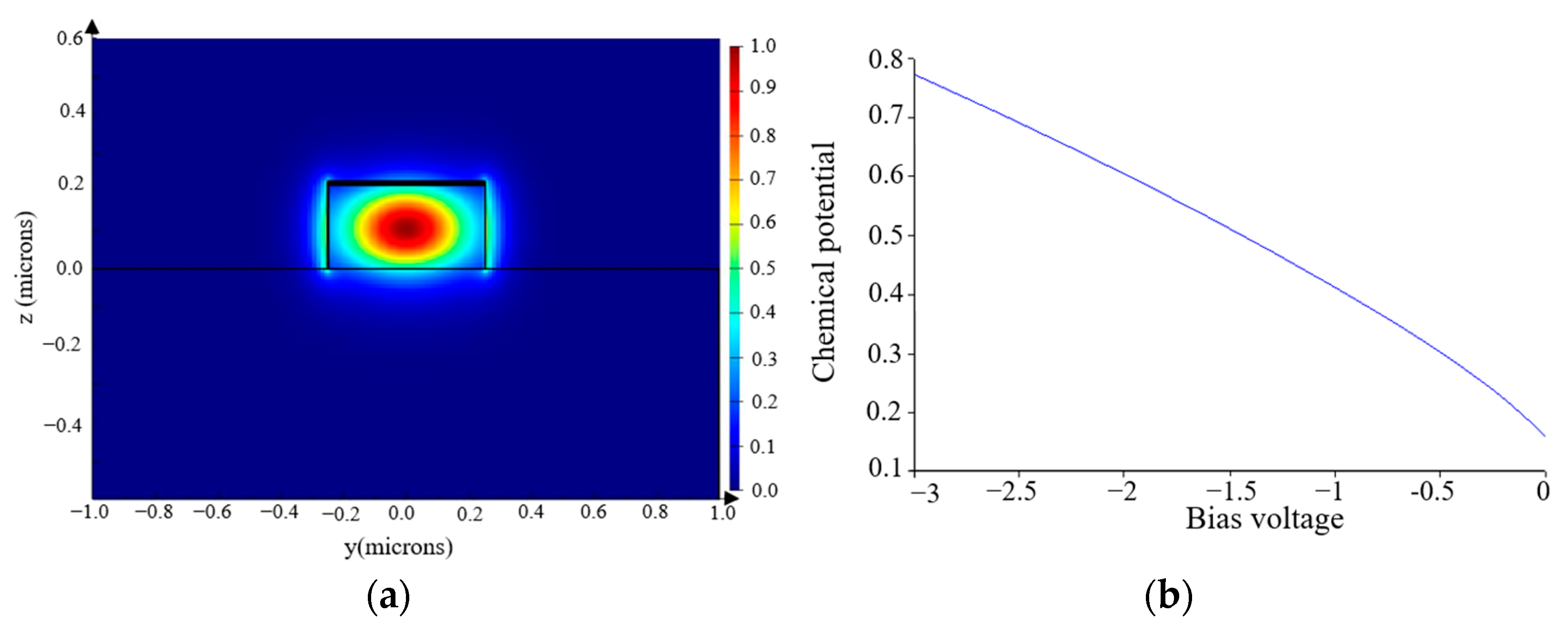
The electrical and optical parameters of materials used for simulations are listed in Table 1. The electric field distribution associated with the only propagating TE mode is shown in Figure 2a and was calculated for c-Si and a-Si:H thicknesses of 220 nm and 0 nm, respectively, meaning that the DLG is at the top. In this case, simulations provide an attenuation per unit length of the waveguide of 0.128 dB/μm at zero bias.
To examine the effect of the Gr bias, an isothermal steady-state electrical simulation was conducted. The top Gr layer was grounded, and a DC sweep was applied to vary the potential of the bottom Gr layer. By monitoring the band structure, the Fermi level can be extracted as the voltage varies, as illustrated in Figure 2b. With the application of a −3 V bias, ε‖ changes, and the optical attenuation decreases to about 0 dB/μm.
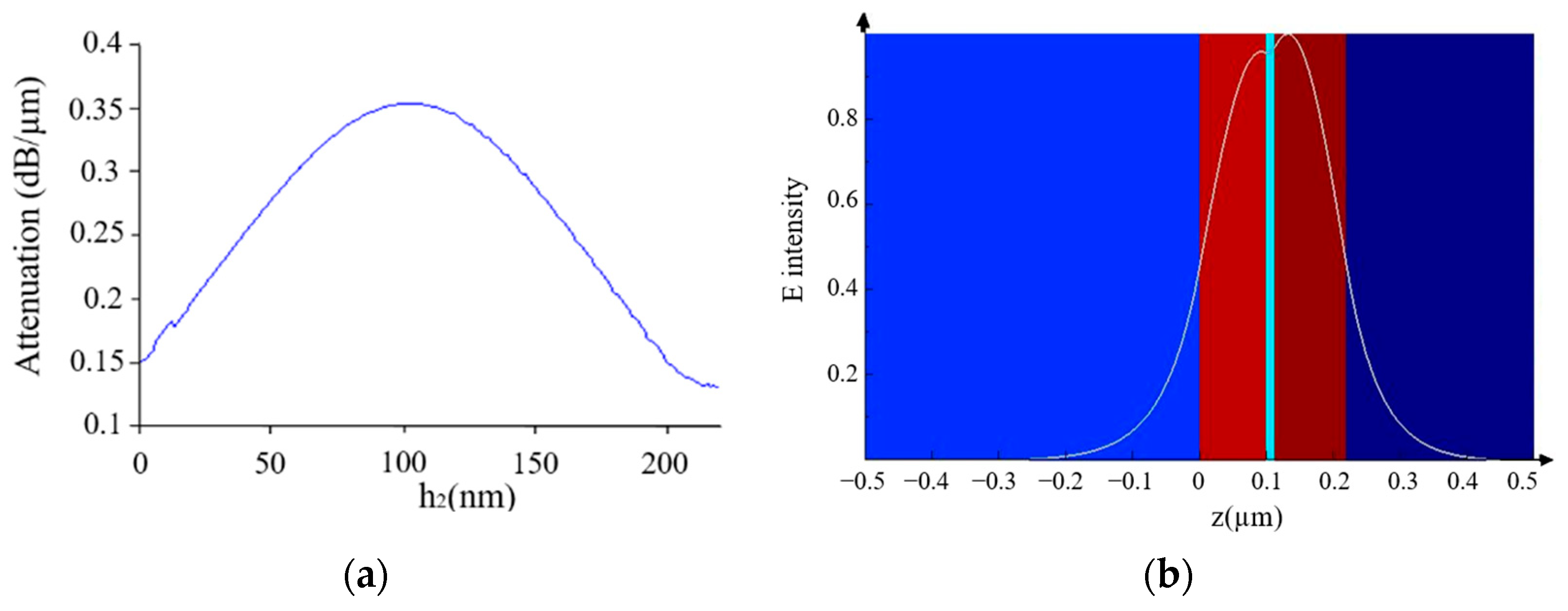
To assess the impact of the GOG position across the waveguide section, parametric simulations were repeated, keeping the overall waveguide thickness constant at 220 nm, while complementarily adjusting the c-Si and a-Si:H thicknesses.
Figure 3a shows the attenuation as a function of h2, namely the thickness of the c-Si layer (see Figure 1), at zero bias. Obviously, the most effective position of the Gr capacitor is close to the half height of the waveguide, where the field intensity is at its maximum, as shown in Figure 3b.
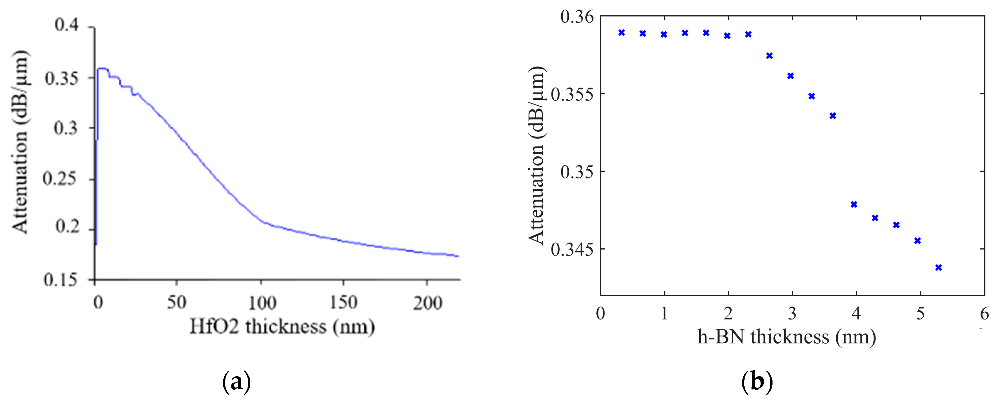
To achieve maximum modulation depth, optimal thicknesses of the h-BN and HfO2 layers were determined, as shown in Figure 4a,b. The parameters yielding the best overall performance are summarized in Table 2. It should be noted that both h-BN and HfO2 thicknesses can be chosen in proper ranges, without significantly affecting the simulation results.

4. Results

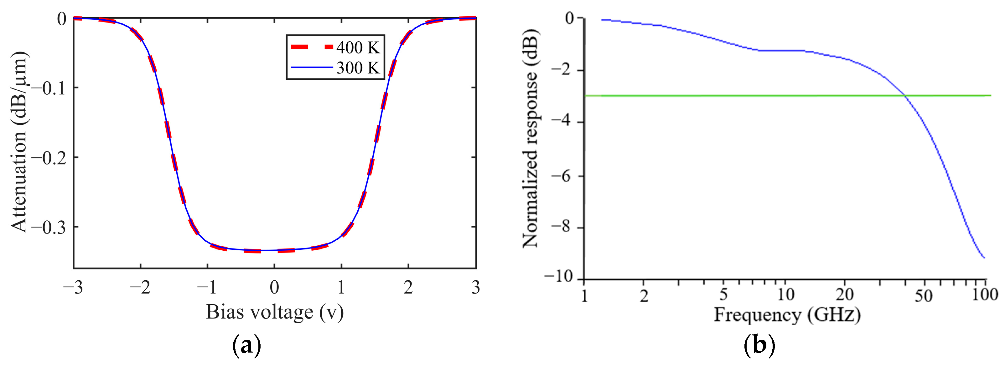
Figure 5a displays the attenuation of a 1550 nm light wave radiation through the optimized modulator for varying drive voltage Vbias. With the current design, the modulation depth, for a 1 μm long device, is as high as 0.34 dB by applying Vbias = −3 V. Transient simulations were also run in the electrical domain. The simulator takes into account the distributed parasitic series resistances, which are mainly concentrated in the graphene layers linking the Au contacts to the actual modulator. Parasitic capacitances are also present and are primarily embedded in the graphene–insulator–graphene structure. These parasitic elements, of course, affect the time response of the modulator. The calculated time-varying Fermi levels and free carrier distributions were used to determine the dynamic optical response.
The dynamic power dissipated at high switching frequencies might produce a heating of the device, which in turn would induce changes in the refractive index of silicon due to the thermo-optic effect. However, the operating principle of the device, based on modulation of absorption in the graphene capacitor, and its optical design, allows it to continue working properly. This is also shown in Figure 5a, where the attenuation as a function of voltage is reported for comparison at 400 K as well, which might be considered a practical operation limit for a photonic device.
Figure 5b shows the calculated frequency dependence of the transmitted signal amplitude for the device, which was obtained from the fast Fourier transform of the output signal in response to a −2.5 V step signal at the input. The −3 dB roll-off frequency is 39.5 GHz, while it is 32 GHz when the GOG structure is at the top.
In order to demonstrate the efficient transmission of digital data, time domain simulations were run to obtain an eye diagram at a receiver for a 50 μm long device, utilizing the Interconnect simulation environment [22], which is specifically designed for the simulation of photonic integrated circuits (PICs). In the setup of the virtual circuit, the signals required for the eye diagram were generated by a random pattern generator (PG), and the modulated light transmitted by the EA modulator was captured using a low-noise, high-frequency photodetector, which was subsequently connected to an oscilloscope. To prevent noise and reflections caused by the impedance mismatch between the modulator and the PG electrical output, the device was terminated using a 50 Ω load. This setup enabled the visualization of the eye diagrams shown in Figure 6 for a 40 Gb/s signal, which was obtained with input pulses switching between −1 V and −3 V. Here, the modulation performances of an EA modulator with the GOG capacitor placed at the waveguide center (exact position as in Table 2) and those obtained by laying the GOC capacitor at the waveguide top are compared. The dynamic ERs are 3.17 dB and 1.2 dB, respectively, showing a comparatively higher efficiency of our optimized device.
Table 3 summarizes the main performances of various double-layer graphene modulators reported so far compared to ours. It shows that, while the extinction ratios (ERs) are comparable to those of existing electro-absorption graphene modulators, the proposed device simultaneously offers a wide bandwidth (BW), high extinction ratio (ER), and compact footprint. Furthermore, it exhibits the highest modulation depth among the compared devices.

5. Conclusions

In this paper, we have investigated a photonic electro-absorption modulator integrating a buried active structure consisting of a graphene–insulator–graphene capacitor to enhance the optical response. The device benefits from the use of such a capacitor in a position where the electric field of the propagating TE mode is at its maximum. In contrast to earlier demonstrations of double-layer graphene modulators, this work introduces a more rigorous physical modeling framework combined with systematic dielectric/structural optimization.
While this optimized structure is not achievable with the standard silicon technology, it can be fabricated instead by introducing the deposition of hydrogenated amorphous silicon (a-Si:H) in the process, allowing the embedding of graphene within a rib waveguide made of c-Si and a-Si:H. In particular, we highlight experimentally feasible integration routes (LT-PECVD a-Si:H and ALD high-k dielectrics), enabling simultaneously enhanced modulation strength and bandwidth within a compact footprint.
The Gr capacitor is then placed in the best position to ensure maximum overlap with the propagating mode. A 0.34 dB/μm attenuation is calculated by numerical simulations at λ = 1550 nm. A realistic bandwidth of 39.5 GHz is estimated using HfO2 as the dielectric, as well as h-BN to encapsulate the graphene layers and preserve high electron mobility. The modulator is capable of operating signals with data transmission speeds of up to 40 Gb/s, with an extinction ratio of 3.17 dB.

Author Contributions

Conceptualization, B.H., F.G.D.C.; methodology, B.H., S.R., M.C., F.G.D.C.; simulations, B.H.; writing: B.H.; verification: B.H., S.R., M.C., F.G.D.C.; supervision, F.G.D.C. All authors have read and agreed to the published version of the manuscript.

Funding

This work was partially supported by the European Union under the Italian National Recovery and Resilience Plan (NRRP) of the NextGenerationEU partnership for “Telecommunications of the Future” (PE00000001—program “RESTART”—FP5 GraPHICs).

Conflicts of Interest

The authors declare no conflicts of interest.

References

  1. Kim, K. 1.1 Silicon technologies and solutions for the data-driven world. In Proceedings of the 2015 IEEE International Solid-State Circuits Conference—(ISSCC) Digest of Technical Papers, San Francisco, CA, USA, 22–26 February 2015; pp. 11–17. [Google Scholar]
  2. Attila, M.; Pinguet, T.; Masini, G.; Sahni, S.; Mack, M.; Gloeckner, S.; De Dobbelaere, P. Advanced Silicon Photonics Transceivers. In Silicon Photonics III; Springer: Berlin/Heidelberg, Germany, 2016; pp. 349–374. [Google Scholar]
  3. Wang, Z.; Ren, W. Mid-infrared optical modulator enabled by photothermal effect. Light. Sci. Appl. 2023, 12, 7. [Google Scholar] [CrossRef]
  4. Passaro, V.M.; De Tullio, C.; Troia, B.; La Notte, M.; Giannoccaro, G.; De Leonardis, F. Recent advances in integrated photonic sensors. Sensors 2012, 12, 15558–15598. [Google Scholar] [CrossRef]
  5. Rauf, R.; Bennett, B. Electrooptical effects in silicon. IEEE J. Quantum Electron. 1987, 23, 123–129. [Google Scholar] [CrossRef]
  6. Agarwal, H.; Terrés, B.; Orsini, L.; Montanaro, A.; Sorianello, V.; Pantouvaki, M.; Watanabe, K.; Taniguchi, T.; Van Thourhout, D.; Romagnoli, M.; et al. 2D–3D integration of hexagonal boron nitride and a high-κ dielectric for ultrafast graphene-based electro-absorption modulators. Nat. Commun. 2021, 12, 1070. [Google Scholar] [CrossRef]
  7. Ai, Z.; Liu, H.; Cheng, S.; Zhang, H.; Yi, Z.; Zeng, Q.; Wu, P.; Zhang, J.; Tang, C.; Hao, Z. Four peak and high angle tilted insensitive surface plasmon resonance graphene absorber based on circular etching square window. J. Phys. D Appl. Phys. 2025, 58, 185305. [Google Scholar] [CrossRef]
  8. Zhao, M.; Hao, Y.; Zhang, C.; Zhai, R.; Zhai, R.; Liu, B.; Liu, W.; Wang, C.; Jafri, H.; Razaq, M.A.; et al. Advances in Two-Dimensional Materials for Optoelectronics Applications. Crystals 2022, 12, 1087. [Google Scholar] [CrossRef]
  9. Liu, M.; Yin, X.; Ulin-Avila, E.; Geng, B.; Zentgraf, T.; Ju, L.; Wang, F.; Zhang, X. A graphene-based broadband optical modulator. Nature 2011, 474, 64–67. [Google Scholar] [CrossRef]
  10. Dalir, H.; Xia, Y.; Wang, Y.; Zhang, X. Athermal Broadband Graphene Optical Modulator with 35 GHz Speed. ACS Photonics 2016, 3, 1564–1568. [Google Scholar] [CrossRef]
  11. Fan, M.; Yang, H.; Zheng, P.; Hu, G.; Yun, B.; Cui, Y. Multilayer graphene electro-absorption optical modulator based on double-stripe silicon nitride waveguide. Opt. Express 2017, 25, 21619–21629. [Google Scholar] [CrossRef]
  12. Giambra, M.A.; Sorianello, V.; Miseikis, V.; Marconi, S.; Montanaro, A.; Galli, P.; Pezzini, S.; Coletti, C.; Romagnoli, M. High-speed double layer graphene electro-absorption modulator on SOI waveguide. Opt. Express 2019, 27, 20145–20155. [Google Scholar] [CrossRef]
  13. Gosciniak, J.; Tan, D.T.H. Theoretical investigation of graphene-based photonic modulators. Sci. Rep. 2013, 3, 1897. [Google Scholar] [CrossRef]
  14. Ye, S.-W.; Yuan, F.; Zou, X.-H.; Shah, M.K.; Lu, R.-G.; Liu, Y. High-Speed Optical Phase Modulator Based on Graphene-Silicon Waveguide. IEEE J. Sel. Top. Quantum Electron. 2016, 23, 76–80. [Google Scholar] [CrossRef]
  15. Della Corte, F.G.; Rao, S.; Nigro, M.A.; Suriano, F.; Summonte, C. Electro-optically induced absorption in α-Si:H/α-SiCN waveguiding multistacks. Opt. Express 2008, 16, 7540–7550. [Google Scholar] [CrossRef] [PubMed]
  16. Rao, S.; Coppola, G.; Gioffrè, M.A.; Della Corte, F.G. A 2.5 ns switching time MachZehnder modulator in as-deposited a-Si:H. Opt. Express 2012, 20, 9351–9356. [Google Scholar] [CrossRef] [PubMed]
  17. Rao, S.; Della Corte, F.G. Numerical Analysis of Electro-Optical Modulators Based on the Amorphous Silicon Technology. J. Light. Technol. 2014, 32, 2399–2407. [Google Scholar] [CrossRef]
  18. Müller, M.; Bouša, M.; Hájková, Z.; Ledinský, M.; Fejfar, A.; Drogowska-Horná, K.; Kalbáč, M.; Frank, O. Transferless Inverted Graphene/Silicon Heterostructures Prepared by Plasma-Enhanced Chemical Vapor Deposition of Amorphous Silicon on CVD Graphene. Nanomaterials 2020, 10, 589. [Google Scholar] [CrossRef] [PubMed]
  19. Lupina, G.; Strobel, C.; Dabrowski, J.; Lippert, G.; Kitzmann, J.; Krause, H.; Wenger, C.; Lukosius, M.; Wolff, A.; Albert, M.; et al. Plasma-enhanced chemical vapor deposition of amorphous Si on graphene. Appl. Phys. Lett. 2016, 108, 193105. [Google Scholar] [CrossRef]
  20. Pizzocchero, F.; Gammelgaard, L.; Jessen, B.S.; Caridad, J.M.; Wang, L.; Hone, J.; Bøggild, P.; Booth, T.J. The hot pick-up technique for batch assembly of van der Waals heterostructures. Nat. Commun. 2016, 7, 11894. [Google Scholar] [CrossRef]
  21. Xiao, Z.; Kisslinger, K.; Chance, S.; Banks, S. Comparison of Hafnium Dioxide and Zirconium Dioxide Grown by Plasma-Enhanced Atomic Layer Deposition for the Application of Electronic Materials. Crystals 2020, 10, 136. [Google Scholar] [CrossRef]
  22. Liao, L.; Bai, J.; Cheng, R.; Lin, Y.-C.; Jiang, S.; Huang, Y.; Duan, X. Top-gated graphene nanoribbon transistors with ultrathin high-k dielectrics. Nano Lett. 2010, 10, 1917–1921. [Google Scholar] [CrossRef]
  23. Giubileo, F.; Di Bartolomeo, A. The role of contact resistance in graphene field-effect devices. Prog. Surf. Sci. 2017, 92, 143–175. [Google Scholar] [CrossRef]
  24. Giannozzi, P.; Baroni, S.; Bonini, N.; Calandra, M.; Car, R.; Cavazzoni, C.; Ceresoli, D. QUANTUM ESPRESSO: A modular and open-source software project for quantum simulations of materials. J. Phys. Condens. Matter 2009, 21, 395502. [Google Scholar] [CrossRef]
  25. De Fazio, D.; Purdie, D.G.; Ott, A.K.; Braeuninger-Weimer, P.; Khodkov, T.; Goossens, S.; Taniguchi, T.; Watanabe, K.; Livreri, P.; Koppens, F.H.L.; et al. High-mobility, wet-transferred graphene grown by chemical vapor deposition. ACS Nano 2019, 13, 8926–8935. [Google Scholar] [CrossRef]
  26. Viti, L.; Purdie, D.G.; Lombardo, A.; Ferrari, A.C.; Vitiello, M.S. HBN-encapsulated, graphene-based, room-temperature terahertz receivers, with high speed and low noise. Nano Lett. 2020, 20, 3169–3177. [Google Scholar] [CrossRef] [PubMed]
  27. Crisci, T.; Moretti, L.; Russo, C.; Gioffré, M.A.; Iodice, M.; Coppola, G.; Casalino, M. Unveiling high responsivity in on-chip photodetectors with graphene interposed between amorphous and crystalline silicon. Carbon 2025, 233, 119837. [Google Scholar] [CrossRef]
  28. Hanson, G.W. Erratum: Dyadic Green’s functions and guided surface waves for a surface conductivity model of graphene. J. Appl. Phys. 2008, 113, 29902. [Google Scholar] [CrossRef]
  29. Arul, N.S.; Nithya, V.D. Two Dimensional Transition Metal Dichalcogenides: Synthesis, Properties, and Applications; Springer: Berlin/Heidelberg, Germany, 2019. [Google Scholar]
  30. Liu, S.; Chen, F. Dynamically tunable Fano resonance effect based on monolayer graphene with disk defect robustness. Phys. B Condens. Matter 2025, 715, 417638. [Google Scholar] [CrossRef]
  31. Phare, C.T.; Lee, Y.-H.D.; Cardenas, J.; Lipson, M. Graphene electro-optic modulator with 30   GHz bandwidth. Nat. Photonics 2015, 9, 511–514. [Google Scholar] [CrossRef]
  32. Nezamdoost, H.; Nikoufard, M.; Saghaei, H. Graphene-based hybrid plasmonic optical electro-absorption modulator on InP platform. Opt. Quantum Electron. 2024, 56, 482. [Google Scholar] [CrossRef]
  33. Eid, M.M.A.; Rashed, A.N.Z.; Sorathiya, V.; Lavadiya, S.; Habib, M.A.; Amiri, I.S. GaAs electro-optic absorption modulators performance evaluation, under high-temperature variations. J. Opt. Commun. 2025, 45, s359–s368. [Google Scholar] [CrossRef]
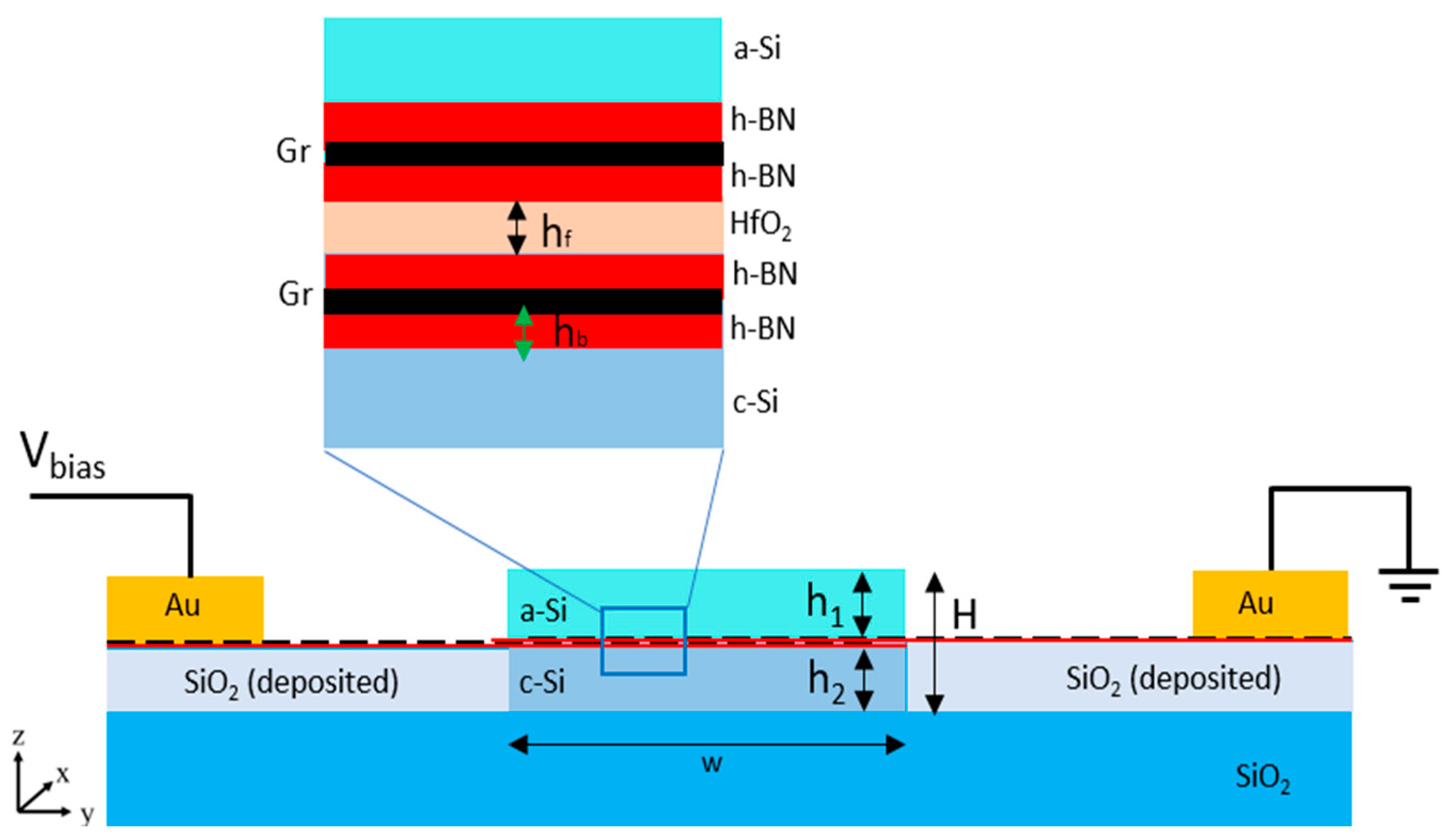
Figure 1. Schematic cross-section (not to scale) of the proposed EA modulator, consisting of a DLG created on a c-Si ridge on SiO2. An a-Si:H stripe, deposited on top, completes the SOI channel waveguide, which, overall, has a 500 nm × 220 nm cross-section. HfO2 is the dielectric material placed between the h-BN layers.
Photonics 12 00916 g001
Figure 2. (a) Electric field distribution for the propagating TE mode. The color map indicates the normalized electric field intensity. The black rectangle outlines the waveguide core region, while the horizontal black line represents the reference z = 0 axis used for field profile extraction; (b) variation in the chemical potential of the bottom graphene sheet as a function of the bias voltage.
Photonics 12 00916 g002
Figure 3. (a) Simulated attenuation as a function of h2 (thickness of the c-Si layer) to find the best position for the Gr capacitor; (b) Electric field intensity as a function of the position of the graphene-on-graphene stack along the z-axis. The color map represents the refractive index profile. The white curve shows the normalized TE-mode electric field intensity profile, while the vertical cyan line indicates the position of the embedded graphene capacitor (h-BN/Gr/h-BN stack).
Photonics 12 00916 g003
Figure 4. (a) Attenuation dependence on hf (HfO2 thickness); (b) attenuation dependence on hb (h-BN thickness) for different layers of h-BN.
Photonics 12 00916 g004
Figure 5. (a) Static electro-optical response of the device for bias voltage Vbias varying from −3 V to 3 V, calculated at 300 K and 400 K; (b) dynamic electro-optical response of the device. These images show the relative electro-optical response of the modulator as a function of frequency obtained by applying pulses of −2.5 V amplitude. The measured −3 dB bandwidth of the device is 39.5 GHz.
Photonics 12 00916 g005
Figure 6. Eye diagrams of the optical signal obtained at 1550 nm for the 50 µm long EA modulator at 40 Gb/s (5 ps/div) for (a) GOG in the middle and (b) GOG at the top of the waveguide. Color scale represents the probability density of signal trajectories: blue regions correspond to fewer occurrences while green/yellow regions indicate regions of highest trajectory density (most probable signal levels).
Photonics 12 00916 g006
Table 1. Properties of used materials.
MaterialRefractive IndexWork Function (eV)
a-Si:H3.574.15
c-Si3.474.15
h-BN1.984.6
HfO21.872.9
SiO21.440.95
Table 2. Parameters that are used in the modulator.
ParameterDescriptionBest Position
h1a-Si:H thickness105 nm
h2c-Si thickness106 nm
hbh-BN thickness0.33–2.31 nm
hfHfO2 thickness2–8 nm
Table 3. Comparison of reported electro-absorption (EA) and electro-optic (EO) modulators based on graphene and other materials (MD = modulation depth; BW = bandwidth; ER = extinction ratio).
RefMD
(dB/µm)
TypeWavelength (nm)Size
(µm × µm)
StructureBW (GHz)ER (dB)ModeYear
This work0.34EA155050 × 0.5Double-layer graphene,
h-BN–HfO2–h-BN
39.53.17TE2025
[6]0.037 EA155060 × 0.45Double-layer graphene394.4TM2021
[12]0.137EA1550120 × 0.65SOI waveguide (air-clad, DLG, 20 nm SiN spacer)291.7TE 2019
[11]0.165EA15501.2 × 18.09Double-stripe Si3N430.6-TE/TM2017
[31]28 dB EO15551 × 0.3Graphene on Si3N4 waveguide ring resonator30-TE2015
[9]0.16 EA153740 × 2Double-layer graphene optical modulator1-TE/TM2011
[32]0.2–0.3EA1550~1 × <1Hybrid plasmonic ridge waveguide7035-2024
[33]15 dB EA130050 × 5GaAs2.5-TE2025
Disclaimer/Publisher’s Note: The statements, opinions and data contained in all publications are solely those of the individual author(s) and contributor(s) and not of MDPI and/or the editor(s). MDPI and/or the editor(s) disclaim responsibility for any injury to people or property resulting from any ideas, methods, instructions or products referred to in the content.