Article

Design of Grating-Embedded Tantalum Pentoxide Microring Resonators with Piezoelectric Tunability

State Key Laboratory of Quantum Functional Materials, School of Microelectronics, Southern University of Science and Technology, Shenzhen 518000, China
*
Author to whom correspondence should be addressed.
Photonics 2025, 12(9), 903; https://doi.org/10.3390/photonics12090903
Submission received: 9 August 2025 / Revised: 3 September 2025 / Accepted: 6 September 2025 / Published: 9 September 2025
(This article belongs to the Special Issue Integrated Waveguide-Based Photonic Devices)

Abstract

Stimulated Brillouin scattering (SBS) in microresonators offers a unique way to develop narrow-linewidth chip-scale lasers. Yet their coherence performance is hindered by the cascaded SBS process, which clamps the output power and broadens the fundamental linewidth of the first-order Stokes wave. Resonance splitting proves to be an effective approach to suppress intracavity SBS cascading. However, precisely aligning and controlling the resonance splitting behavior remains challenging. We address these issues by proposing a piezoelectrically actuated grating-embedded tantalum pentoxide (Ta2O5) microring resonator. This microresonator comprises a Bragg grating segment that induces a counter-propagating wave and a ring segment that is integrated with a lead zirconate titanate (PZT) actuator. The half-circumference Bragg grating has a peak reflectivity of 31% at 1549.8 nm and a bandwidth of 88.89 pm, which is narrow enough to ignite resonance splitting in only one azimuthal mode. The PZT actuator empowers the resonator with a frequency tuning rate of 0.1726 GHz/V, particularly useful for post-fabrication compensation and splitting control. The proposed architecture offers a promising solution to breaking the intracavity cascaded SBS chain with frequency tuning capability, paving the way towards highly coherent chip-scale laser sources.

1. Introduction

Narrow-linewidth lasers play a critical role in fields that require high coherence, such as coherent communication [1,2], optical fiber sensing [3,4,5], atomic and quantum sensing [6], atomic clocks [7], and ultra-low-noise microwaves [8,9,10]. Owing to the narrow gain bandwidth, stimulated Brillouin scattering (SBS) proves to be a unique mechanism to reduce pump laser fundamental linewidth, and has been demonstrated in a variety of photonic platforms including silicon (Si) [11], silicon oxynitride (SiON) [12], lithium niobate (LiNbO3) [13], and silicon nitride (Si3N4) [14,15]. Chip-scale SBS lasers often employ high-quality (Q) factor microresonators for resonance enhancement [15]. The microresonators’ free spectral ranges (FSRs) are carefully designed to match the SBS frequency shift. However, the discrete resonance series could trigger cascaded SBS if the first-order Stokes power is strong enough and the higher-order Stokes waves are resonance-enhanced. This is undesirable for narrow-linewidth lasers since SBS cascading will clamp the first-order Stokes power and broaden its fundamental linewidth [16]. Breaking the SBS cascading chain is the key to tackling this problem.
The suppression of high-order Brillouin scattering can be realized through various methods. One way is to explore different mode families without fixed FSRs. Resonances of different modes can only be utilized to enhance the pump and the first-order Stokes waves, but not higher-order Stokes waves (i.e., S2) [17]. However, this method relies on the coincidence of matching the resonance spacing with the Brillouin shift. Thus, extensive screening of the resonances is inevitable. Another way is to utilize the resonances from the same mode family, which is more predictable. As long as the S2 Stokes wave fails to be resonance-enhanced, the SBS cascading chain will be broken. This could be manifested by artificially generated resonance splitting through mode hybridization in photonics molecules [14] or through back-reflection in grating-embedded microresonators [18].
Photonic crystal microring resonators have recently gained dramatic attention in integrated nonlinear photonics. By incorporating Bragg gratings around the circumference of the ring resonator, a counter-clockwise (CCW) mode is induced owing to the Bragg reflection, and is hybridized with the original clockwise (CW) propagating mode, resulting in mode splitting near the Bragg wavelength. Such devices are extremely useful for Kerr frequency comb generation [19,20] and high-order SBS mode suppression [18]. However, their proper functioning requires the precise alignment of the Bragg wavelength and the resonant wavelength, which poses challenges for passive devices. The lack of frequency tuning capability in passive devices may lead to deteriorated splitting performance or even malfunctions [19]. Although thermal tuning could mitigate the problem and achieve the desired resonance splitting [21], this method also suffers from high power consumption and may not apply to platforms that are of low thermo-optic coefficients, such as tantalum pentoxide (Ta2O5) [22].
To address this challenge, we propose a piezoelectrically actuated grating-embedded microring resonator architecture. This microresonator consists of two segments: one is a Bragg grating-embedded segment, and the other is the ring segment that could be integrated with a lead zirconate titanate (PZT) actuator. The Bragg grating has a peak reflectivity of 31% at 1549.8 nm to generate a counter-propagating wave and resonance splitting. It occupies half the circumference of the microring to guarantee a narrow-linewidth Bragg reflection spectrum, so that resonance splitting only happens on one azimuthal mode. The PZT actuator is composed of a molybdenum/lead zirconate titanate/aluminum layer, which empowers the resonator with a frequency tuning rate of 0.1726 GHz/V. By manipulating the bias voltage, the resonant wavelength and the Bragg wavelength can be accurately aligned, and the amount of resonance splitting can be controlled. To the best of our knowledge, this is the first design of grating-embedded piezoelectric-actuated Ta2O5 microresonator. It not only provides a promising solution to breaking the intracavity cascaded SBS chain, but also finds wide applications in dispersion engineering [19,21], biosensing [23], and quantum computing [24]. Although this approach is demonstrated in the emerging Ta2O5 platform, the conclusions and methodology could also be applied to Si3N4 and other platforms.

2. Design Principle

2.1. Design of the Microresonator

We designed the tunable photonic crystal ring resonator in the low-loss, CMOS-compatible Ta2O5 platform [22]. The waveguide cross-section was selected to be 2.8 µm × 90 nm, whose propagation loss has been experimentally characterized to be ~0.5 dB/cm based on our prior work [22,25]. Both the top and the bottom cladding layers are 5 µm thick. Shown in Figure 1b is the normalized electric field profile of the TE00 mode. Its effective refractive index ( n e f f ) and group index (ng) are 1.4773 and 1.5980, respectively. The mode is weakly guided since a considerable amount of power propagates in the silicon dioxide (SiO2) cladding, resembling a diluted silicon nitride (Si3N4) mode [26,27]. Thus, it is reasonable to borrow the acoustic wave velocity in the diluted Si3N4 waveguides to estimate the Brillouin frequency shift in the high-aspect-ratio Ta2O5 waveguides. The Brillouin frequency shift is calculated as follows:
Ω B =   2 n e f f V a c λ
where V a c = 5706 m/s is the acoustic velocity adopted from Ref. [28], λ is the pump wavelength, and the Brillouin shift Ω B is ~10.88 GHz. To simultaneously enhance the pump and the first-order Stokes (S1) waves inside the cavity, the free spectral range (FSR) of the microcavity needs to be an integer fraction of the Brillouin shift (i.e., Ω B = l · F S R and l is an integer). Thus, the radius of the microring, R , is set as 5.49 mm, and the corresponding FSR is approximately one half of the Brillouin frequency shift (in this case, l = 2 ).

2.2. Design of Bragg Grating

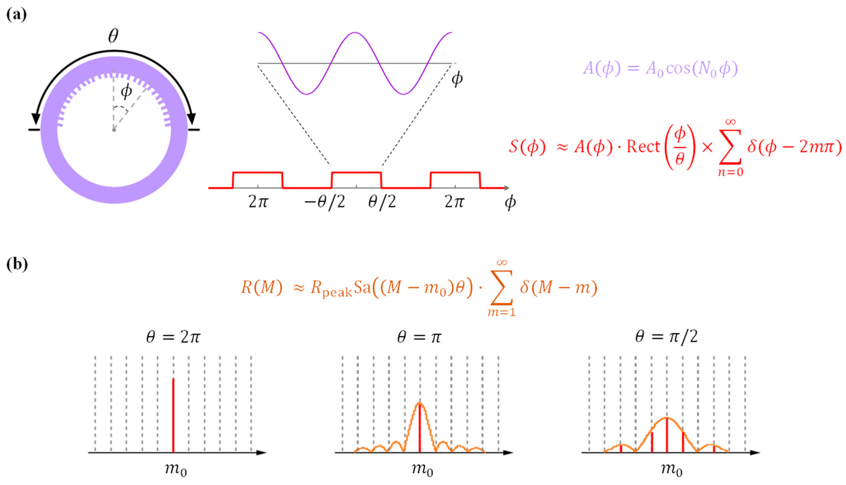
To pursue frequency detuning between the resonant wavelength and the Bragg wavelength, a segmented photonic crystal resonator is preferred over an endless photonic crystal resonator [29], because it has the flexibility to adjust the optical path of each segment individually [21]. For a segmented photonic crystal ring resonator with a sinusoidal grating profile ( A 0 cos ( N 0 ϕ ) ), the spatial modulation along the circumference can be viewed as the multiplication of the grating profile ( A 0 cos ( N 0 ϕ ) ) with a window function ( R e c t ( ϕ θ ) ), as shown in Figure 2a, where A 0 is the grating amplitude, N 0   is the angular frequency, θ is the angular width of the window, and ϕ is the angle in radian. As noted in pioneer works [20,21], the mode-splitting profile of a given cavity mode is related to the Fourier transform of the modulation in its effective refractive index. However, only the full-round ( θ = 2 π ) and half-round ( θ = π ) modulated resonators can restrain mode splitting in only one resonance. Shorter grating segments have broader backscattering profiles, leading to mode splitting at multiple resonances Figure 2b. This is undesirable in S2 Stokes wave suppression, since the S1 Stokes wave resonance enhancement may be jeopardized if the spectral width of the backscattering is larger than the Brillouin frequency shift. In other words, the Bragg grating bandwidth must be narrower than twice the Brillouin frequency shift, corresponding to 4 × F S R of the cavity in this work. For demonstration purposes, we choose the Bragg grating bandwidth to be twice the cavity’s FSR. Therefore, the half-round grating-modulated ring resonator structure is adopted as a trade-off between the single mode-splitting operation and the frequency tuning capability.
The resonant wavelengths of a microring resonator are regulated by
2 π R n e f f = m λ
where m is the azimuthal number and n e f f is the resonator’s effective refractive index. On the other hand, the Bragg reflection wavelength is determined by
λ B = 2 Λ n G
where Λ is the grating pitch and n G is the grating waveguide’s effective refractive index. For a full-round modulated resonator, the number of the pitch N must follow N Λ = 2 π R . Assuming that the Bragg wavelength λ B aligns with one of the resonant wavelengths λ 0 and that n G n e f f , one can find N = 2 m 0 . It is worth noting that N should be an even number so as to fulfill a half-round modulated resonator. By leveraging the simulated effective mode index n G n e f f = 1.4773 and the optimized radius R = 5.49 mm, we choose the grating parameters N =   65,762 and Λ = 524.54 nm. Correspondingly, the Bragg wavelength is λ B =   1549.8 nm and m 0 = 32,881.
The grating amplitude determines the coupling strength κ , the Bragg reflection bandwidth Δ λ B , and the peak power reflectivity at the Bragg wavelength R p a e k . For sinusoidal gratings, these relations are as follows [30]:
κ = π Δ n G 2 λ B
R p e a k = t a n h 2 ( κ L )
Δ λ B = λ B 2 π n g κ 2 + π L 2
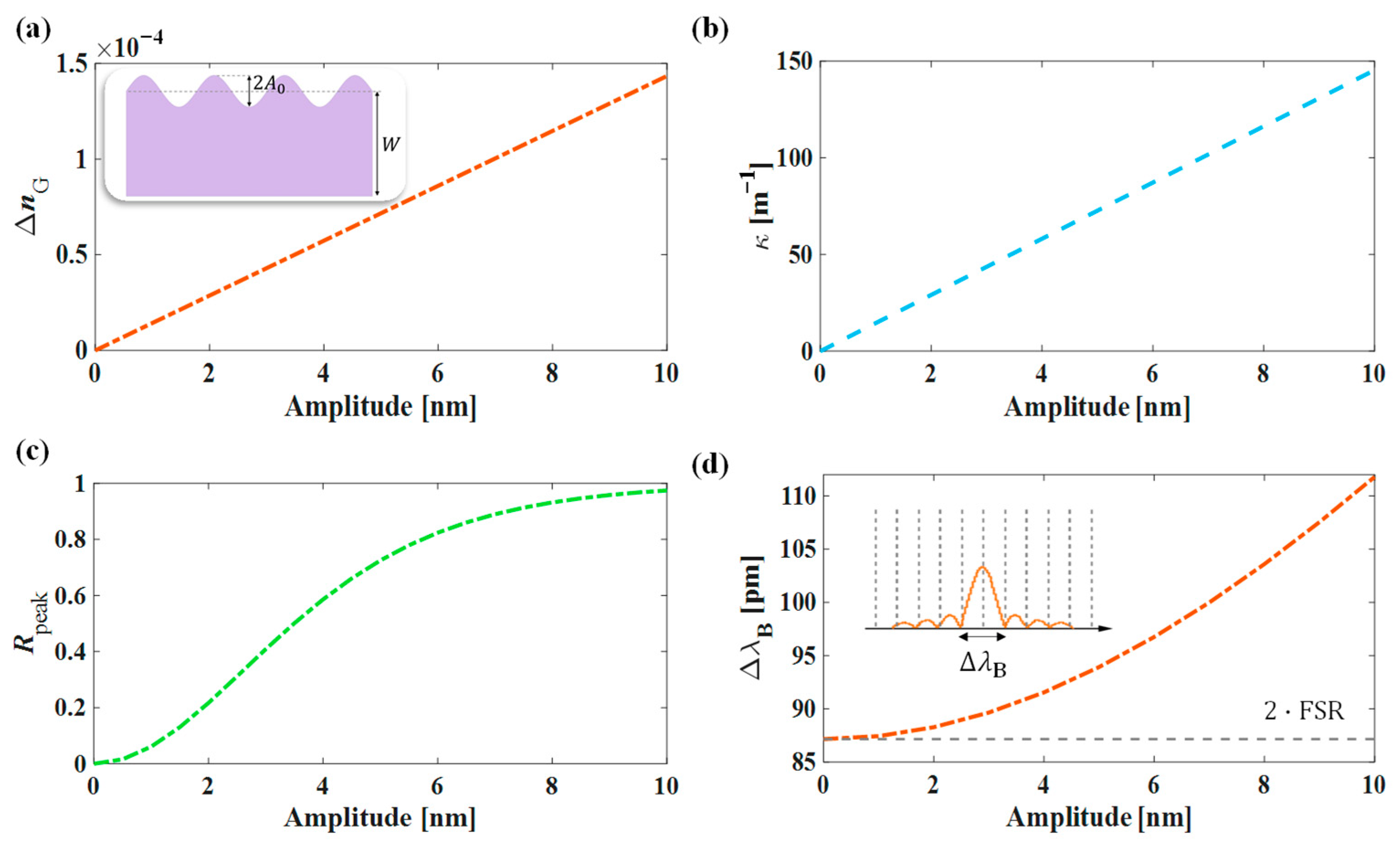
where Δ n G is defined as the difference of the n G between the widest and narrowest grating waveguides, and n g is the group index. For the half-round modulated resonator, the grating length is L = 1 2 N Λ = 17.24 mm. Figure 3 illustrates the impact of the grating amplitude A 0 on the Δ n G (a), κ (b), Rpeak (c), and Δ λ B (d).
As the grating amplitude increases, the modulation on the grating waveguide’s effective mode index becomes stronger Figure 3a, leading to an increased coupling between the CW mode and the CCW mode Figure 3b and a more prominent peak power reflectivity Figure 3c. However, the Bragg reflection bandwidth, defined as the separation between the first nulls in the inset figure in Figure 3d, becomes wider with the increasing coupling strength Figure 3d. In this case, the resonances besides m 0 may also experience non-zero reflection, which is against our design purpose of allowing only one resonant mode to be reflected by the Bragg grating. As a trade-off between the mode coupling strength and the Bragg reflection bandwidth, we choose an amplitude A 0 = 2.5 nm. Correspondingly, the coupling strength is 36.33 m−1 and the peak power reflectivity is 0.31. The Bragg reflection bandwidth is 88.89 pm, close to the targeted 2FSR spacing.

2.3. Design of Piezoelectric Actuator

To enable reconfigurable mode splitting, we propose electrical phase modulation on the non-grating ring segment to tune the resonant wavelengths. Since Ta2O5 waveguides have low thermo-optic coefficients [22] and are widely used in athermal photonic devices [31], piezoelectric tuning is preferred over thermal tuning. This tuning method has drawn tremendous attention in the photonic community recently [32,33,34], because piezoelectric tuning equips passive photonic devices with active modulation capabilities, unleashing great potential in optical signal processing, quantum computing, and laser frequency stabilization.
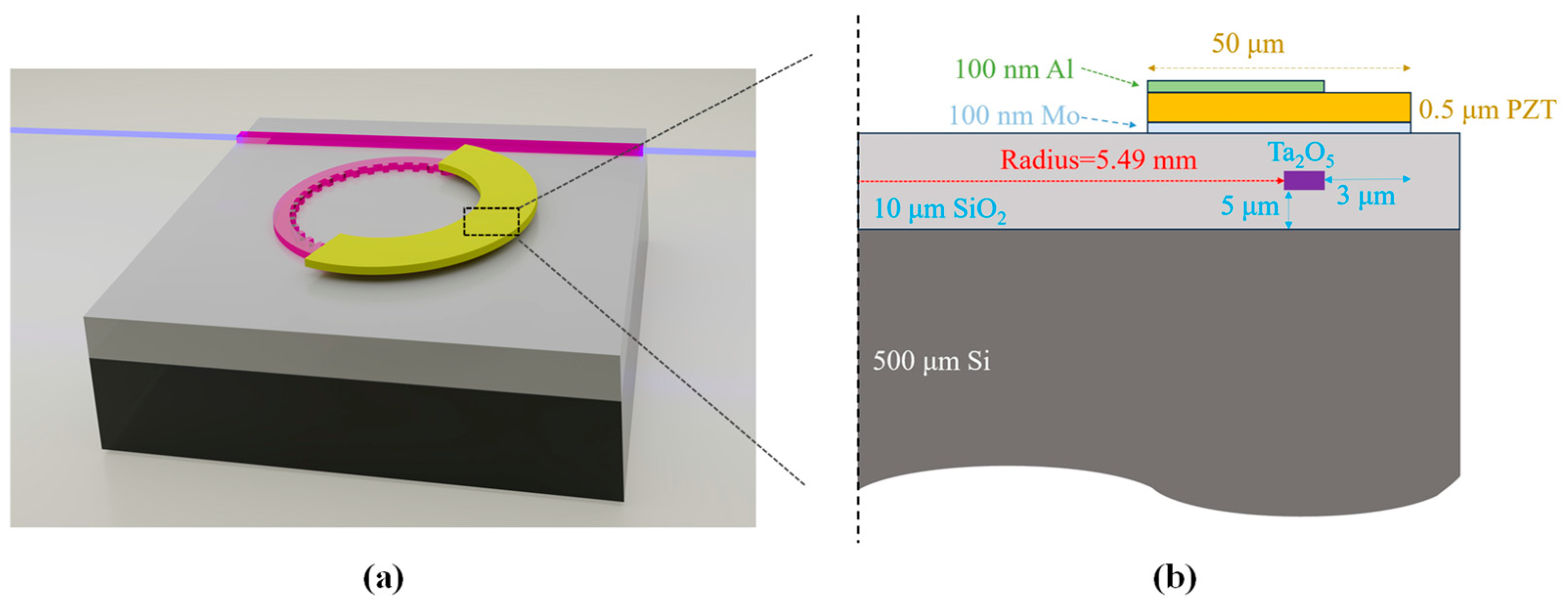
The cross-section of the modulation section is illustrated in Figure 4. The Ta2O5 waveguide core is 2.8 µm × 90 nm, and the top and bottom SiO2 cladding thicknesses are 5 µm. The ring radius is 5.49 mm as discussed before. On top of the waveguide cladding sits a piezoelectric actuator, which is composed of 100 nm molybdenum (Mo)/0.5 µm lead zirconate titanate (PZT-5H)/100 nm aluminum (Al) from bottom to top. The width of the PZT layer is initially set as 50 µm, and the top Al is 3 µm shorter to avoid electrical shorts in fabrication. The structure is simulated in a Finite-Element-Method (FEM) solver (COMSOL Multiphysics®) in a 2D axisymmetric model.
The key player of the piezo-actuator is the PZT layer. When an external voltage is applied between the Al and Mo layers, the PZT layer will be deformed, driven by the converse piezoelectric effect [35], which is expressed as follows [36]:
T = c E S e T E
D = e S + ϵ 0 ϵ r s E
where c E and e are the material stiffness matrix and piezoelectric coupling matrix [36], T is the stress, S is the strain, D is the electric displacement field, and E is the electric field. The coefficients of the PZT material are listed in Table 1.
The mechanical stress is simulated by applying the voltage between the top Al layer and the bottom Mo layer. Figure 5a shows the distribution of the z component of the stress on the device. The piezoelectric-effect-induced stress leads to structure deformation, assuming the device has a fixed constraint on the outer edge and the bottom of the disc with free boundary elsewhere. The deformed structure is illustrated in Figure 5b.
The impact of the stress on materials’ refractive indices is captured in the following equations [32]:
n r = n 0 C 1 σ r C 2 σ φ + σ z
n φ = n 0 C 1 σ φ C 2 σ z + σ r
n z = n 0 C 1 σ z C 2 ( σ r + σ φ )
where n r , φ , z is the material’s refractive index of the corresponding direction, r ,   φ ,   z are the spatial directional vectors in the cylindrical coordinate, n 0 is the materials’ refractive index without any stress applied, σ is the stress, C 1 = n 0 3 p 11 2 ν p 12 / 2 E and C 2 = n 0 3 p 12 ν p 11 + p 12 / 2 E are the first and second stress optical coefficients [38], E = 1.36 × 10¹¹ Pa,   ν =   0.27 are Young’s modulus and Poisson’s ratio [39], p 11 =   −0.030 and p 12 =   0.074 are strain-optic constants [40], respectively. The calculated C 1 and C 2 are listed in Table 2.
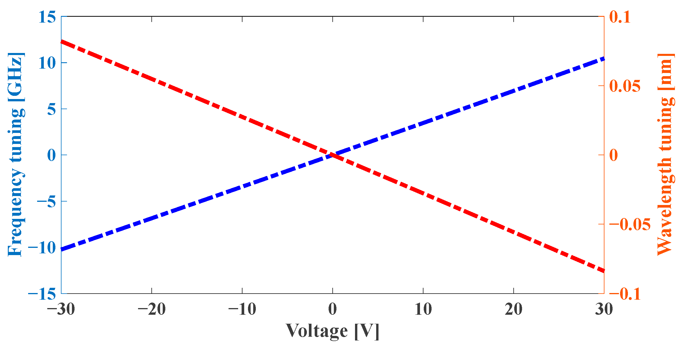
The resonance mode near the Bragg wavelength is tracked by specifying the azimuthal mode number m 0 = 32,881, defined in Section 2.2, in the simulator. Given the applied external voltage and the induced mechanical stress, the effective mode index of the guided mode is altered, resulting in a detuning of its resonant frequency. We sweep the applied voltage across the Al and the Mo layers. The resonant frequency for the targeted azimuthal mode is correspondingly solved at each voltage. Figure 6 shows that the resonant wavelength and frequency shift with respect to the external voltage, demonstrating the piezo-actuated modulation effect. The modulation efficiency, extracted from the slope of the curve, is 0.3451 GHz/V. It is worth noting that this axisymmetric model captures the full-round ring modulator behavior; therefore, the actual modulation efficiency should be reduced by half, that is, 0.1726 GHz/V, to represent a half-round actuated ring modulator. To tune the wavelength from one resonance to its adjacent one (1FSR), the required voltage is 31.64 V. Therefore, the maximum voltage range in aligning the resonant wavelength and the Bragg wavelength is ±31.64 V.

3. Resonance Splitting Modeling Using Coupled-Mode Theory

The Bragg reflection-induced resonance splitting is modeled using the coupled-mode theory (CMT) [41,42]:
d a 1 d t = i ω + i γ 0 2 a 1 + i g 12 a 2 + i γ c s i n
d a 2 d t = i ω + i γ 0 2 a 2 + i g 21 a 1  
s o u t = s i n + i γ c a 1
where a 1 and a 2 represent the CW and CCW field, Δ ω is the frequency detuning between the laser frequency and the resonant frequency, g is the coupling rate (resulting from the reflection of the Bragg grating) between the two fields, g 12 =   g 21 g 0 S a M m 0 θ , where g 0 = R p e a k c / n g L [43], γ 0 represents the total loss rate of the mode and is assumed to be the same for both the CW and the CCW modes, γ c represents the external coupling rates from the bus waveguide to the ring for the CW mode [39], and s o u t and s i n represent the input and output fields. When the system reaches the steady state, both d a 1 d t and d a 2 d t are zero, yielding the field transfer function, H , as follows:
H = s o u t s i n = 1 i γ c / 2 ω g 12 + i γ 0 2 + i γ c / 2 ω + g 12 + i γ 0 2
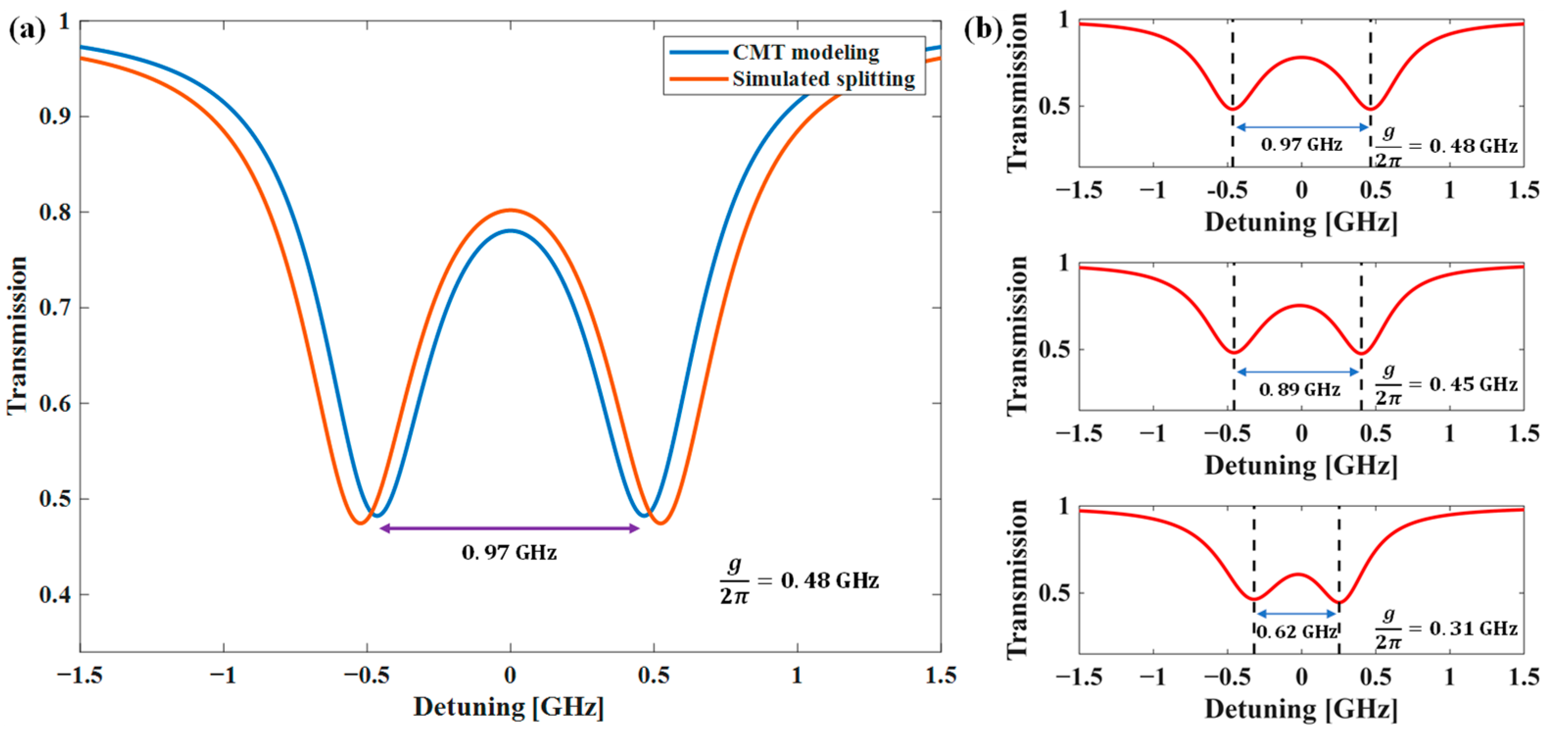
Using the parameter set of γ 0 =   3.04   G   r a d / s , γ c =   0.88   G   r a d / s , and g 21 = g 12 = 2 π × 0.48   G   r a d / s , the power transmission, H 2 , is depicted as the blue curve in Figure 7a. Resonance splitting is clearly observed and is also confirmed numerically in Lumerical INTERCONNECT®. The simulated transmission is plotted as the orange curve in Figure 7a. The theoretical and the simulated curves show excellent agreement, proving the correctness of the CMT model.
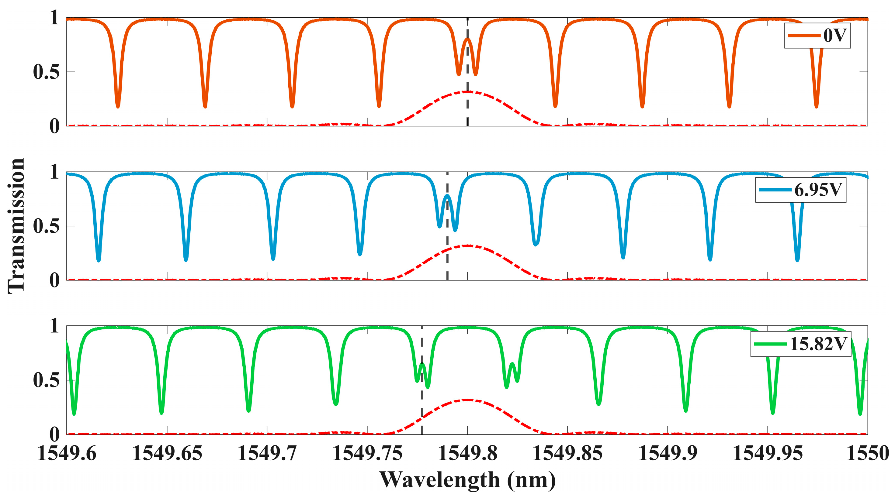
The amount of mode splitting could be adjusted by the coupling rate g , as illustrated in Figure 7b. The larger g is, the wider the separation between the split resonances. The parameter g not only depends on the Bragg reflectivity R p e a k , but also the detuning between the Bragg wavelength and the resonant wavelength. For our half-round grating-embedded resonator, piezo actuation takes effect on the ring segment rather than the grating segment, meaning that the resonant wavelength will shift in response to external voltage while the Bragg wavelength remains relatively still. By applying different voltages, the resonant wavelength of the microresonator will change at a rate of 0.1726 GHz/V, which leads to a controllable resonance splitting around the Bragg wavelength. Figure 8 shows the resonance splitting profiles when different voltage is applied to the piezoelectric actuator. As the voltage increases, the resonant wavelength of m 0 = 32881 blue-shifts (black dashed line), and its resonance splitting diminishes due to the detuning between the Bragg wavelength and resonant wavelength.
To assess the high-order SBS suppression performance, we analyze and compare the first Stokes wave (S1) power with and without the presence of the Bragg gratings [16,44],
P S 1 = 4 γ c 2 γ 0 2 P t h P i n P t h
P t h = ω P γ 0 3 8 μ γ c
P t h , S 2 = 4 P t h
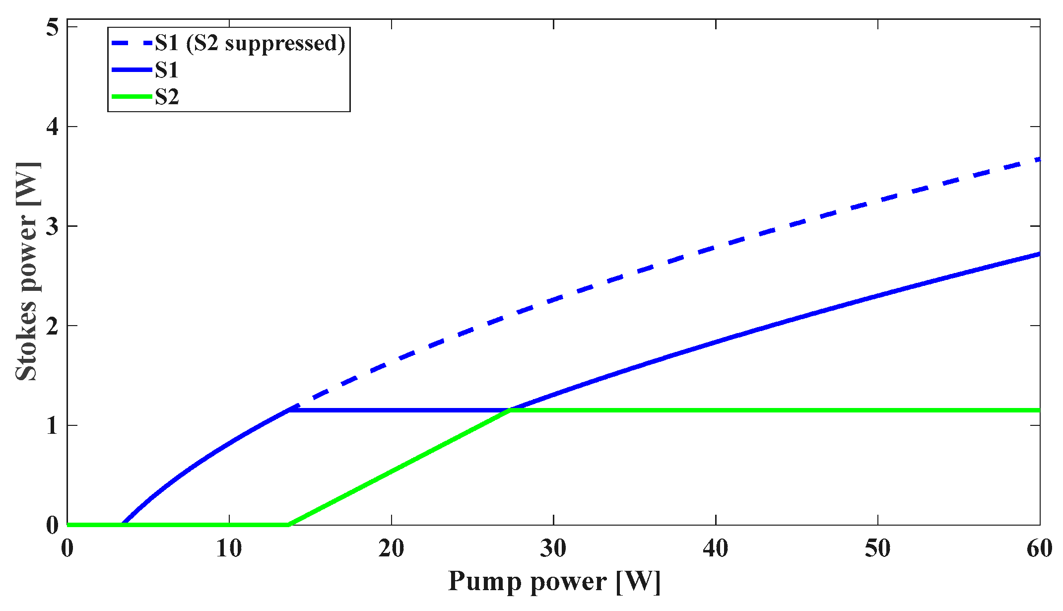
where = 1.054   × 10   34   J · s 1 is the reduced Planck constant, μ = 3.8   m H z is half of the Brillouin amplification rate per pump photon [16], ω P =   2 π ×   193.44   T   r a d / s is the optical angular frequency, γ 0 = 3.04 / 2 π   G H z , and γ c = 0.88 / 2 π   G H z . The threshold power of the second-order Stokes wave (S2) is approximately four times that of the S1 wave, which is 3.41 W. As shown in Figure 9, the relationship between input pump power and Stokes output with and without S2 suppression confirms that suppressing cascaded SBS allows unclamped S1 power scaling beyond conventional limits. Our results demonstrate that resonance splitting significantly enhances sustainable first-order Stokes power output, even above the second-order Stokes threshold, effectively disrupting the cascaded Brillouin scattering process. This improvement directly validates our approach’s effectiveness in enabling high-power narrow-linewidth operation through configurable mode splitting.

4. Discussion

In summary, we propose a novel half-round grating-embedded tantalum pentoxide microresonator whose resonance splitting could be controlled by an integrated piezoelectric actuator, aiming to suppress the cascaded stimulated Brillouin scattering with convenient frequency alignment. The half-round grating design not only guarantees that resonance splitting occurs at a single azimuthal mode, but also leaves room for piezoelectric actuator integration, which can tune the resonant wavelength precisely. The microring radius is designed to be 5.49 mm, critical to resonance-enhancing the pump and the first-order Stokes waves simultaneously. The optimized Bragg grating has a bandwidth of 88.89 pm (twice the cavity’s FSR) and a peak reflectivity of 31%. The PZT-actuated microresonator possesses a frequency tuning rate of 0.1726 GHz/V. By manipulating the bias voltage, the resonant wavelength and the Bragg wavelength can be accurately aligned, and the amount of resonance splitting can be controlled.
A comparison between the performance in this work and other SBL works is given in Table 3. Unlike grating-embedded microresonators with no frequency tuning capability, our work introduces piezoelectrically reconfigurable resonance control, which enables post-fabrication compensation and adjustment. Compared to thermal tuning, our piezoelectric approach is faster and more energy efficient. With the help of reconfigurable resonance splitting and easy frequency alignment, this device offers a feasible solution to breaking the cascaded SBS chain, paving the way toward high-power and narrow-linewidth chip-scale Brillouin lasers, with significant implications for ultra-precision atomic clocks, low-noise coherent communications, quantum sensing, and microwave photonics. The fabrication of the proposed device is ongoing and experimental characterization will be performed in the near future.

Author Contributions

Conceptualization, Q.Z.; methodology, J.H. (Jiazhao He) and M.Y.; software, J.H. (Jiazhao He) and M.Y.; validation, J.H. (Jiazhao He), M.Y. and Q.Z.; formal analysis, J.H. (Jiazhao He) and Q.Z.; investigation, J.Z., N.D., Z.Z., Z.L. (Zhengqi Li), X.T., W.C., J.H. (Jiaxin Hou) and S.W.; data curation, J.H. (Jiazhao He) and Z.L. (Zhenyu Liu); writing—original draft, J.H. (Jiazhao He); writing—review & editing, J.H. (Jiazhao He) and Q.Z.; supervision, Q.Z.; project administration, Q.Z.; funding acquisition, Q.Z. All authors have read and agreed to the published version of the manuscript.

Funding

National Natural Science Foundation of China (62205137); Guangdong Provincial Quantum Science Strategic Initiative (GDZX2304009); Basic and Applied Basic Research Foundation of Guangdong Province (2023A1515012141); Guangdong Provincial Pearl River Talent Program (2023QN10X204); Shenzhen Science and Technology Program (JCYJ20241202125420027); High-level Special Funds (G03034K007); and the SUSTech Undergraduate Innovation and Entrepreneurship Training Program (X202514325051).

Data Availability Statement

The data supporting this study’s findings are available from the corresponding author upon reasonable request.

Acknowledgments

The authors acknowledge the assistance of SUSTech Core Research Facilities.

Conflicts of Interest

The authors have no conflicts to disclose.

References

  1. Kikuchi, K. Fundamentals of Coherent Optical Fiber Communications. J. Light. Technol. 2016, 34, 157–179. [Google Scholar] [CrossRef]
  2. Blumenthal, D.J.; Ballani, H.; Behunin, R.O.; Bowers, J.E.; Costa, P.; Lenoski, D.; Morton, P.A.; Papp, S.B.; Rakich, P.T. Frequency-Stabilized Links for Coherent WDM Fiber Interconnects in the Datacenter. J. Light. Technol. 2020, 38, 3376–3386. [Google Scholar] [CrossRef]
  3. Lu, P.; Lalam, N.; Badar, M.; Liu, B.; Chorpening, B.T.; Buric, M.P.; Ohodnicki, P.R. Distributed Optical Fiber Sensing: Review and Perspective. Appl. Phys. Rev. 2019, 6, 041302. [Google Scholar] [CrossRef]
  4. Mecozzi, A.; Antonelli, C.; Mazur, M.; Fontaine, N.; Chen, H.; Dallachiesa, L.; Ryf, R. Use of Optical Coherent Detection for Environmental Sensing. J. Light. Technol. 2023, 41, 3350–3357. [Google Scholar] [CrossRef]
  5. Ip, E.; Fang, J.; Li, Y.; Wang, Q.; Huang, M.-F.; Salemi, M.; Huang, Y.-K. Distributed Fiber Sensor Network Using Telecom Cables as Sensing Media: Technology Advancements and Applications [Invited]. J. Opt. Commun. Netw. 2022, 14, A61–A68. [Google Scholar] [CrossRef]
  6. Xu, C.; Zhang, L.; Huang, S.; Ma, T.; Liu, F.; Yonezawa, H.; Zhang, Y.; Xiao, M. Sensing and Tracking Enhanced by Quantum Squeezing. Photon. Res. 2019, 7, A14–A26. [Google Scholar] [CrossRef]
  7. Ludlow, A.D.; Boyd, M.M.; Ye, J.; Peik, E.; Schmidt, P.O. Optical Atomic Clocks. Rev. Mod. Phys. 2015, 87, 637–701. [Google Scholar] [CrossRef]
  8. Wang, B.; Yang, Z.; Zhang, X.; Yi, X. Vernier Frequency Division with Dual-Microresonator Solitons. Nat. Commun. 2020, 11, 3975. [Google Scholar] [CrossRef] [PubMed]
  9. Li, J.; Lee, H.; Vahala, K.J. Microwave Synthesizer Using an On-Chip Brillouin Oscillator. Nat. Commun. 2013, 4, 2097. [Google Scholar] [CrossRef] [PubMed]
  10. Morton, P.A.; Morton, M.J. High-Power, Ultra-Low Noise Hybrid Lasers for Microwave Photonics and Optical Sensing. J. Light. Technol. 2018, 36, 5048–5057. [Google Scholar] [CrossRef]
  11. Otterstrom, N.T.; Behunin, R.O.; Kittlaus, E.A.; Wang, Z.; Rakich, P.T. A Silicon Brillouin Laser. Science 2018, 360, 1113–1116. [Google Scholar] [CrossRef]
  12. Ye, K.; Klaver, Y.; Jimenez Gordillo, O.A.; Botter, R.; Daulay, O.; Morichetti, F.; Melloni, A.; Marpaung, D. Brillouin and Kerr Nonlinearities of a Low-Index Silicon Oxynitride Platform. APL Photonics 2023, 8, 051302. [Google Scholar] [CrossRef]
  13. Rodrigues, C.C.; Schilder, N.J.; Zurita, R.O.; Magalhães, L.S.; Shams-Ansari, A.; Alegre, T.P.M.; Lončar, M.; Wiederhecker, G.S. On-Chip Backward Stimulated Brillouin Scattering in Lithium Niobate Waveguides. In Proceedings of the 2024 Conference on Lasers and Electro-Optics (CLEO), Charlotte, NC, USA, 5–10 May 2024; pp. 1–2. [Google Scholar]
  14. Liu, K.; Wang, J.; Chauhan, N.; Harrington, M.W.; Nelson, K.D.; Blumenthal, D.J. Integrated Photonic Molecule Brillouin Laser with a High-Power Sub-100-mHz Fundamental Linewidth. Opt. Lett. 2024, 49, 45–48. [Google Scholar] [CrossRef]
  15. Nelson, K.D.; Puckett, M.W.; Wu, J. A Ring-Laser Gyro Based on Stimulated Brillouin Scattering in Silicon Nitride Waveguides. In Proceedings of the 2020 IEEE Research and Applications of Photonics in Defense Conference (RAPID), Miramar Beach, FL, USA, 10–12 August 2020; pp. 1–3. [Google Scholar]
  16. Behunin, R.O.; Otterstrom, N.T.; Rakich, P.T.; Gundavarapu, S.; Blumenthal, D.J. Fundamental Noise Dynamics in Cascaded-Order Brillouin Lasers. Phys. Rev. A 2018, 98, 023832. [Google Scholar] [CrossRef]
  17. Wang, M.; Liu, C.; Zhou, X.; Li, J.; Wang, Z.; Yang, D.-Q.; Yang, Q.-F.; Li, B.-B. Cascading-Induced Fundamental Linewidth Enhancement of a Microcavity Brillouin Laser. ACS Photonics 2025, 12, 2318–2324. [Google Scholar] [CrossRef]
  18. Puckett, M.; Bose, D.; Nelson, K.; Blumenthal, D.J. Higher Order Cascaded SBS Suppression Using Gratings in a Photonic Integrated Ring Resonator Laser. In Proceedings of the 2019 Conference on Lasers and Electro-Optics (CLEO), San Jose, CA, USA, 5–10 May 2019; pp. 1–2. [Google Scholar]
  19. Kheyri, M.; Zhang, S.; Bi, T.; Pal, A.; Zhang, H.; Zhang, Y.; Alabbadi, A.; Yan, H.; Ghosh, A.; Hill, L.; et al. On-Chip Microresonator Dispersion Engineering via Segmented Sidewall Modulation. Photon. Res. 2025, 13, 367–372. [Google Scholar] [CrossRef]
  20. Moille, G.; Lu, X.; Stone, J.; Westly, D.; Srinivasan, K. Fourier Synthesis Dispersion Engineering of Photonic Crystal Microrings for Broadband Frequency Combs. Commun. Phys. 2023, 6, 144. [Google Scholar] [CrossRef]
  21. Li, J.; Zhang, Y.; Zeng, J.; Yu, S. Broadband and Accurate Electric Tuning of On-Chip Efficient Nonlinear Parametric Conversion. Optica 2025, 12, 424–432. [Google Scholar] [CrossRef]
  22. Liu, Z.; Yao, W.; You, M.; Yu, X.; Ding, N.; Cheng, W.; Li, Z.; Tang, X.; Guo, F.; Lu, D.; et al. Tantalum Pentoxide Integrated Photonics: A Promising Platform for Low-Loss Planar Lightwave Circuits with Low Thermo-Optic Coefficients. ACS Photonics 2025, 12, 684–695. [Google Scholar] [CrossRef]
  23. Goede, M.; Dijkstra, M.; Chang, L.; Acharyya, N.; Kozyreff, G.; Obregon, R.; Martinez, E.; García-Blanco, S. Mode-Splitting in a Microring Resonator for Self-Referenced Biosensing. Opt. Express 2020, 29, 346–358. [Google Scholar] [CrossRef]
  24. Chen, Y.; Duan, J.; Li, J.; Chen, Y.; Li, J.; Duan, J.; Xu, X.; Wang, J. High-Order Autler–Townes Splitting in Electrically Tunable Photonic Molecules. Photonics Res. 2024, 12, 1794. [Google Scholar] [CrossRef]
  25. Geng, Z.; Cheng, W.; Yan, Z.; Yi, Q.; Liu, Z.; You, M.; Yu, X.; Wu, P.; Ding, N.; Tang, X.; et al. Low-Loss Tantalum Pentoxide Photonics with a CMOS-Compatible Process. Opt. Express 2024, 32, 12291–12302. [Google Scholar] [CrossRef]
  26. Liu, K.; Jin, N.; Cheng, H.; Chauhan, N.; Puckett, M.W.; Nelson, K.D.; Behunin, R.O.; Rakich, P.T.; Blumenthal, D.J. Ultralow 0.034 dB/m Loss Wafer-Scale Integrated Photonics Realizing 720 Million Q and 380 μW Threshold Brillouin Lasing. Opt. Lett. 2022, 47, 1855–1858. [Google Scholar] [CrossRef]
  27. Zhao, Q.; Harrington, M.; Isichenko, A.; Liu, K.; Behunin, R.; Papp, S.; Rakich, P.; Hoyt, C.; Fertig, C.; Blumenthal, D. Integrated Reference Cavity with Dual-Mode Optical Thermometry for Frequency Correction. Optica 2021, 8, 1481–1487. [Google Scholar] [CrossRef]
  28. Blumenthal, D.; LIU, K.; Jin, N.; Cheng, H.; Chauhan, N.; Puckett, M.; Nelson, K.; Behunin, R.; Rakich, P. Supplementary Document for Ultra-Low 0.034 dB/m Loss Wafer-Scale Integrated Photonics Realizing 720 Million Q and 380 μW Threshold Brillouin Lasing—5717781.Pdf. Opt. Lett. 2022, 47, 1855–1858. [Google Scholar] [CrossRef]
  29. Yu, S.-P.; Cole, D.C.; Jung, H.; Moille, G.T.; Srinivasan, K.; Papp, S.B. Spontaneous Pulse Formation in Edgeless Photonic Crystal Resonators. Nat. Photonics 2021, 15, 461–467. [Google Scholar] [CrossRef]
  30. Chrostowski, L.; Hochberg, M. Silicon Photonics Design: From Devices to Systems; Cambridge University Press: Cambridge, UK, 2015; ISBN 978-1-316-23711-3. [Google Scholar]
  31. You, M.; Liu, Z.; Cheng, W.; Tang, X.; Ding, N.; Li, Z.; Wang, M.; Shen, L.; Zhao, Q. Athermal Tantalum Pentoxide Mach-Zehnder Interferometers Based on Structural Compensation Method. IEEE Photonics J. 2025, 17, 1–8. [Google Scholar] [CrossRef]
  32. Tian, H.; Liu, J.; Dong, B.; Skehan, J.C.; Zervas, M.; Kippenberg, T.J.; Bhave, S.A. Hybrid Integrated Photonics Using Bulk Acoustic Resonators. Nat. Commun. 2020, 11, 3073. [Google Scholar] [CrossRef]
  33. Stanfield, P.R.; Leenheer, A.J.; Michael, C.P.; Sims, R.; Eichenfield, M. CMOS-Compatible, Piezo-Optomechanically Tunable Photonics for Visible Wavelengths and Cryogenic Temperatures. Opt. Express 2019, 27, 28588–28605. [Google Scholar] [CrossRef]
  34. He, J.; You, M.; Liu, Z.; Li, Z.; Cheng, W.; Ding, N.; Tang, X.; Hou, J.; Zhao, Q. Simulation of Stress-Optic Microresonator Modulator. Available online: https://cn.comsol.com/paper/simulation-of-stress-optic-microresonator-modulator-137612 (accessed on 1 January 2025).
  35. Bu, G.; Ciplys, D.; Shur, M.; Schowalter, L.J.; Schujman, S.; Gaska, R. Electromechanical Coupling Coefficient for Surface Acoustic Waves in Single-Crystal Bulk Aluminum Nitride. Appl. Phys. Lett. 2004, 84, 4611–4613. [Google Scholar] [CrossRef]
  36. COMSOL Multiphysics® v. 6.0. www.comsol.com. COMSOL AB. Stockholm, Sweden.
  37. Fang, D.; Li, F.; Liu, B.; Zhang, Y.; Hong, J.; Guo, X. Advances in Developing Electromechanically Coupled Computational Methods for Piezoelectrics/Ferroelectrics at Multiscale. Appl. Mech. Rev. 2013, 65, 0802. [Google Scholar] [CrossRef]
  38. Huang, M. Stress Effects on the Performance of Optical Waveguides. Int. J. Solids Struct. 2003, 40, 1615–1632. [Google Scholar] [CrossRef]
  39. Zhao, Q.; Behunin, R.O.; Rakich, P.T.; Chauhan, N.; Isichenko, A.; Wang, J.; Hoyt, C.; Fertig, C.; Lin, M.H.; Blumenthal, D.J. Low-Loss Low Thermo-Optic Coefficient Ta2O5 on Crystal Quartz Planar Optical Waveguides. APL Photonics 2020, 5, 116103. [Google Scholar] [CrossRef]
  40. Nakagawa, Y.; Yawata, M.; Kakio, S. Enhancement of Photoelastic Constant of Optical Thin Film Waveguide Assisted by Surface Acoustic Wave. Ultrasonics 2000, 38, 590–593. [Google Scholar] [CrossRef]
  41. Souza, M.C.M.M.; Rezende, G.F.M.; Barea, L.A.M.; Wiederhecker, G.S.; Frateschi, N.C. Modeling Quasi-Dark States with Temporal Coupled-Mode Theory. Opt. Express 2016, 24, 18960–18972. [Google Scholar] [CrossRef]
  42. Suh, W.; Wang, Z.; Fan, S. Temporal Coupled-Mode Theory and the Presence of Non-Orthogonal Modes in Lossless Multimode Cavities. IEEE J. Quantum Electron. 2004, 40, 1511–1518. [Google Scholar] [CrossRef]
  43. Little, B.E.; Chu, S.T.; Haus, H.A.; Foresi, J.; Laine, J.-P. Microring Resonator Channel Dropping Filters. J. Light. Technol. 1997, 15, 998–1005. [Google Scholar] [CrossRef]
  44. LIU, K.; Wang, J.; Chauhan, N.; Harrington, M.; Nelson, K.; Blumenthal, D. Supplementary Document for Integrated Photonic Molecule Brillouin Laser with High Power Sub-100-mHz Fundamental Linewidth—6720603.Pdf. Opt. Lett. 2024, 49, 45–48. [Google Scholar] [CrossRef]
Figure 1. (a) SBS cascading in a microresonator without (top) and with (bottom) resonance splitting. (b) Schematic of a grating-embedded microresonator with a PZT actuator integrated on top. The inset illustrates the waveguide dimensions and TE mode field profile.
Photonics 12 00903 g001
Figure 2. (a) The spatial modulation along the circumference can be approximated by a sinusoidal function multiplied by a window function and convolved with a series of delta functions. (b) The reflection spectra of the grating-embedded resonators with different window width θ .
Photonics 12 00903 g002
Figure 3. (a) The waveguide effective index variation as a function of the grating amplitude. (b) The Bragg coupling coefficient as a function of the grating amplitude. (c) The peak reflectivity of the Bragg grating as a function of the grating amplitude. (d) The bandwidth of the Bragg grating as a function of the grating amplitude.
Photonics 12 00903 g003
Figure 4. (a) An artistic view of the piezo-actuated half-round grating-embedded ring resonator. (b) The cross-section of the piezoelectric actuator and the ring waveguide.
Photonics 12 00903 g004
Figure 5. (a) The distribution of the z component of the stress tensor at 30 V bias voltage. (b) The displacement illustrates deformation of the device with a scaling factor of 50 to exaggerate the visual effect. The colormap represents the displacement magnitude of the device.
Photonics 12 00903 g005
Figure 6. The frequency detuning of the piezo-actuated full-round microring resonator.
Photonics 12 00903 g006
Figure 7. (a) The comparison of the resonance splitting calculated by the coupled-mode theory (blue) and simulated by Lumerical INTERCONNECT (orange). (b) The separation of resonance splitting changes with the value of g .
Photonics 12 00903 g007
Figure 8. The transmission spectra of the half-round grating-embedded microring resonator under different applied voltages. The red dashed line represents the Bragg reflection spectrum, and the black dashed line marks the resonance of m 0 = 32881.
Photonics 12 00903 g008
Figure 9. Expected S1 and S2 output power with and without high-order SBS suppression.
Photonics 12 00903 g009
Table 1. Material properties of the piezoelectric layer.
ParameterValueReference
e P Z T 5 H
[C/m2]
0 0 0 0 17.0 0 0 0 0 17.0 0 0 6.5 6.5 23.3 0 0 0 [37]
c E , P Z T 5 H
[GPa]
127.205 80.2122 84.6702 0 0 0 80.2122 127.205 84.6702 0 0 0 84.6702 84.6702 117.436 0 0 0 0 0 0 22.9885 0 0 0 0 0 0 22.9885 0 0 0 0 0 0 23.4742 [36]
ϵ r s , P Z T 5 H 1704.4 0 0 0 1704.4 0 0 0 1433.6 [36]
Table 2. Material properties employed in stress-optic simulation.
ParameterValueReference
n 0 2.058[39]
C 1 −2.24 × 10⁻¹² [m2/N][38,39,40]
C 2 1.99 × 10⁻¹² [m2/N][38,39,40]
Table 3. Comparison with prior SBL works.
Ref.This work[11][18][14]
MaterialTa2O5SiSi3N4Si3N4
TypeGrating-resonatorracetrack resonatorGrating-resonatorPhotonic molecule
Propagation loss~50 dB/m0.034 dB/m
TunabilityPZTThermal heater
Cascaded SBS suppression
Tuning efficiency0.1726 GHz/V
Disclaimer/Publisher’s Note: The statements, opinions and data contained in all publications are solely those of the individual author(s) and contributor(s) and not of MDPI and/or the editor(s). MDPI and/or the editor(s) disclaim responsibility for any injury to people or property resulting from any ideas, methods, instructions or products referred to in the content.