Article

Design of a Modified Moiré Varifocal Metalens Based on Fresnel Principles

Precision Measurement Laboratory, Zhejiang Sci-Tech University, Hangzhou 310018, China
*
Author to whom correspondence should be addressed.
Photonics 2025, 12(9), 888; https://doi.org/10.3390/photonics12090888
Submission received: 13 August 2025 / Revised: 29 August 2025 / Accepted: 2 September 2025 / Published: 3 September 2025

Abstract

This paper proposes a Fresnel-based Modified Moiré Varifocal Metalens (MMVL) addressing the inherent defocus at 0° rotation and significant focal quality degradation during varifocal operation in Traditional Moiré Varifocal Metalenses (TMVLs). The transmission function of the Fresnel-modified Moiré metalens combines a static term with a dynamic term, allowing the MMVLs to effectively overcome these limitations. Meanwhile, to minimize energy losses arising from polarization conversion and diffraction between the two metalenses, the nano-units on the metalenses are optimized by Particle Swarm Optimization (PSO) with FDTD simulations, maximizing the polarization conversion efficiency and transmittance. The simulation results demonstrate superior focal quality and stability in the MMVL throughout full rotational cycles, with super-diffraction-limited focusing maintained across all varifocal states. MMVLs have advantages in robustness; under axial distance variation (d = 0–20 d 0 , 0–3 μm), they maintain on-axis focus without deviation; with centering error (p = 0–10 p 0 , 0–3 μm), they sustain a clear focus at >36% efficiency. These results confirm that MMVLs have enhanced tolerance to manufacturing/assembly errors compared to TMVLs, delivering significantly stabilized optical performance. This advancement enables new possibilities for integrated micro-optics and optical tweezer applications.

1. Introduction

Since the advent of lens technology, lenses have served as pivotal optical components in diverse domains, from daily life to precision imaging and advanced medical diagnostics and therapeutics. With rapid advances in modern optics and interdisciplinary fields, demands for enhanced performance and flexibility in optical systems continue to grow. Consequently, dynamically tunable lenses have become imperative for frontier applications: high-resolution medical imaging [1,2,3,4,5]; microscopic imaging techniques [6,7]; high-speed optical communications [8,9]; optical tweezers [10,11]; precision laser beam shaping [12,13]; and adaptive optics [14,15]. However, traditional refractive lenses with fixed curvatures suffer from inherent limitations: Once fabricated, their focal lengths and key optical parameters remain immutable. Dynamic focusing typically requires complex mechanical systems [16,17] (such as motor-driven translation stages) or lens-switching assemblies [18]. These approaches substantially increase system volume, weight, power consumption, and mechanical complexity while reducing response speed and reliability—fundamentally hindering their deployment in miniaturized/integrated devices [19,20].
In recent years, breakthroughs in nanotechnology and metamaterials have brought revolutionary changes to optical design. Metalenses—composed of subwavelength nanostructures like nanoantennas or resonators—now enable the full-vector control of light’s phase, amplitude, and polarization at subwavelength scales [21,22,23], fundamentally transforming traditional light manipulation. This planar architecture offers disruptive advantages: ultrathin form factors (the thickness can reach the wavelength level) with chip-integration compatibility [24,25]; superior chromatic aberration correction [26]; flexible polarization control [27]; and resolution beyond the diffraction limit [28,29]. These properties establish metalenses as potential successors to refractive lenses, especially in space-constrained microsystems (such as miniature spectrometers and cell-sized endoscopes). However, the focus of a metalens is also fixed once fabricated. To achieve a varifocal metalens, researchers have proposed several methods. Convergence with microfluidics, functional materials, and MEMS has enabled dynamic focusing via thermal modulation (requiring embedded microheaters) [30,31]; electrical control (needing precision electrodes) [32,33]; optical-field varifocals (dependent on auxiliary excitation) [34]; PCM refractive-index switching [35,36]; liquid-crystal reorientation [37,38]; MEMS-driven displacement [39,40]; microfluidic adjustment [41]; and mechanical stretching [42]. Critically, many methods require external subsystems, such as heating circuits for thermal control or electrodes for electrical tuning, which escalate design complexity, manufacturing difficulty, and integration costs.
Compared with other methods, Moiré Varifocal Metalenses (MVLs) stand out due to their unique passive tuning mechanism. The moire varifocal metalens is a kind of device which consists of two metalenses. The two metalenses are designed properly and allow parallel incident light to focus at a certain point. By rotating the two metalenses to make them have a relative angle, the focus point is changed to realize the varifocal function [43,44,45,46,47]. Critically, this structure requires no external subsystems, preserving the intrinsic integration advantages and system simplicity of metalenses. These advantages make moire varifocal metalenses suitable for studies which require small devices, such as optical tweezer control and microfluidic chip design. However, traditional Moiré varifocal metalenses (TMVLs) have two inherent limitations—defocus at 0° rotation and progressive focal degradation during varifocal operation—which severely limit the practical application of TMVLs. To overcome these limitations, a Fresnel-based Modified Moiré Varifocal Metalens (MMVL) is proposed in this paper. This approach improves focal performance degradation and enhances robustness against misalignment errors, enabling improved applicability in optical tweezers, miniature endoscopes, and other fields.

2. Materials and Methods

2.1. Design of Nano-Units for Varifocal Metalens

Subwavelength-scale nano-units serve as the fundamental building blocks for the precise manipulation of the phase, amplitude, and polarization of incident light in metalenses. In this work, geometric phase control is employed to enable accurate wavefront shaping. As illustrated in Figure 1, each nano-unit comprises two components: a nano-pillar and a substrate. The nano-pillar features a cuboid geometry and is fabricated from silicon (Si), while the substrate is a cubic structure composed of silicon dioxide (SiO2). The primary function of the nano-unit in this design is to convert incident left-handed circularly polarized (LCP) light into right-handed circularly polarized light, a process accompanied by the introduction of a geometric phase delay [48].
The use of geometric phase control significantly simplifies both the design and fabrication processes of the nano-units. However, due to the intrinsic characteristics of the Moiré metalens, materials with high optical transmittance are required, and the nano-units must operate as near-ideal half-wave plates. This is critical for minimizing diffraction losses between the metalenses and enhancing the overall efficiency of polarized light utilization.
To achieve high optical transmittance while maintaining fabrication feasibility, silicon dioxide (SiO2) is selected due to its excellent transmittance and widespread availability. To ensure that the nano-pillars function as near-ideal half-wave plates—and thereby maximize the polarization conversion efficiency—the Particle Swarm Optimization (PSO) algorithm [49] is employed to optimize key geometric parameters, including length (L), width (W), height (H), and period (P). PSO is a stochastic, swarm-intelligence-based algorithm that navigates complex search spaces through simulated social behavior and self-adjustment. According to the characteristics of the nano-pillar, this paper configured a four-dimensional search space with 100 particles and 200 iterations, bounding all parameters between 60 nm and 1000 nm. The initial particle positions were randomized within these bounds. To concurrently maximize the transmittance (T) and polarization conversion efficiency ( P o l _ r ), their product is defined as the Figure of Merit (FOM), as shown in Equation (1).
F O M = P o l _ r · T   amongthese   M a x : P o l _ r = r e a l ( P z _ r ) / 2 d x d y s o u r c e p o w e r ( λ ) T
P o l _ r denotes the polarization conversion efficiency from left-circular to right-circular polarization, P z _ r is the Poynting vector, sourcepower ( λ ) stands for the source power at wavelength λ , and T signifies the transmittance of the nano-pillar.
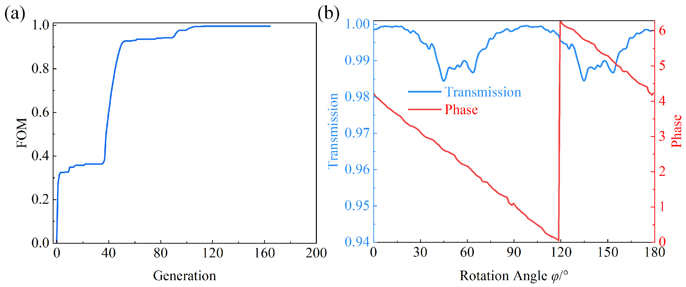
In order to more accurately reflect the true performance of the nano-pillar, this paper combines the Particle Swarm Optimization (PSO) algorithm with the commercial software Finite Difference Time Domain (FDTD) Solutions to optimize the structural parameters of the nano-pillar. Firstly, the particle parameters updated in each iteration of the PSO algorithm are substituted into the FDTD Solutions software. Secondly, by running a script, a structural model of the nano-unit is established with periodic boundary conditions. The incident light is chosen to be left circularly polarized light with a wavelength of 1064 nm, which is commonly used in fields such as optical tweezers [50]. Then, the script is executed to obtain the electric and magnetic field data of the nano-unit structure. Based on these data, the transmittance T and polarization conversion efficiency Pol_r are calculated. Finally, the Figure of Merit (FOM) is fed back into the PSO algorithm. The iteration of the algorithm stops when the FOM exceeds 0.98 and the optimal FOM value remains unchanged for 50 consecutive generations or the maximum number of iterations is reached. The overall optimization process of the PSO is illustrated in Figure 2a. After optimization, the final parameters of the nano-pillar are obtained as follows: L = 294 nm, W = 160 nm, H = 530 nm, and P = 441 nm. To facilitate the subsequent design of the metalens, the optimized nano-pillar parameters are adjusted. The final selected parameters are L = 295 nm, W = 160 nm, H = 530 nm, and P = 440 nm. In existing research [51], nano-units with these dimensional parameters can meet practical manufacturing standards. Figure 2b shows that the geometric phase delay Φ of the nano-pillar can be obtained by adjusting the rotation angle φ of the nano-pillar. When the rotation angle varies from 0° to 180°, a full variation from 0 to 2 π can be achieved, and the average transmittance across all angles is 0.9944.

2.2. Design of the Modified Varifocal Metalens

Traditional Moiré Varifocal Metalenses (TMVLs) operate based on the Moiré effect. The Moiré effect is an optical interference phenomenon that arises when two or more similar periodic grating patterns are superimposed. By periodically shifting or rotating these overlapping patterns in space, Moiré fringes are formed within the overlapping region. Equation (2) defines the transmission function and phase distribution function of TMVLs.
T 1 = e i a r 2 φ T 2 = e i a r 2 φ a = 1 P D Φ 1 = a r 2 φ Φ 2 = a r 2 φ
T 1 and T 2 denote the transmission functions, while Φ 1 and Φ 2 are the phase distributions of the TMVLs, r is the radial distance from any point to the center of the metalens, φ is the azimuthal angle measured from the x-axis, P is the nano-unit period, and D represents the diameter of the metalens.
TMVLs achieve varifocal tuning through the relative rotation of T 1 and T 2 , which generates a combined transmission function T j o i n t . Consequently, the resulting phase distribution—and thus the focal spot position—is controlled by the rotation angle θ . This relationship is described by Equation (3).
T joint = T 1 · T 2 = e i ( a r 2 φ a r 2 φ θ ) = e i a r 2 θ
Although TMVLs offer advantages such as a wide varifocal range, structural simplicity, and ease of adjustment, the focal quality degrades drastically as the rotation angle θ increases. Notably, at θ = 0°, the focus becomes undefined—corresponding to an infinite focal length—which is incompatible with practical application requirements.
This study addresses the inherent limitations in TMVLs, including focal quality degradation during varifocal operation and the loss of axial focus at the rotational null position ( θ = 0°). To overcome these challenges, an improved approach based on Fresnel diffraction theory is proposed. By constructing a Fresnel mathematical model, the light-field modulation characteristics of Fresnel diffraction are effectively integrated into the Moiré metalens structure. This integration overcomes the inherent drawbacks of TMVLs at θ = 0° while preserving their varifocal characteristics, significantly enhancing focal stability during varifocal operation. Specifically, an inverse design method based on Fresnel diffraction principles is employed to design the phase functions for the two metalens surfaces. Firstly, a point source is positioned within a predefined focal range using the inverse design approach based on Fresnel diffraction theory. Then, the Fresnel diffraction model is applied to derive the mathematical model for the Fresnel phase distribution across this focal range. Based on this derived phase distribution, the phase profiles of the two Moiré metalenses are subsequently designed. This method effectively mitigates the defocusing issue observed in TMVLs at a rotation angle of 0°, achieving focal quality in close agreement with Fresnel theory. Moreover, it enables the focal spot to maintain high quality throughout the full rotation of the metalens, thereby substantially enhancing its varifocal performance.

2.3. Phase Design Based on Fresnel

To improve the inherent limitations of TMVLs, the MVLs are designed based on Fresnel diffraction theory. The governing equation is given as follows.
U 2 ( x 2 , y 2 ) = e j k z j λ z + + [ U 1 x 1 , y 1 · e j k 2 z x 2 x 1 2 + y 2 y 1 2 ] · d x d y
U 2 ( x 2 , y 2 ) denotes the complex amplitude distribution on the metalens plane. λ is the wavelength of the light wave. z represents the distance from the origin to the observation plane. k is the wave number, defined as k = 2 π / λ . U 1 ( x 1 , y 1 ) is the amplitude distribution of the source on the diffraction plane at ( x 1 , y 1 ), describing the initial amplitude of the incident light field.
Based on the principle of inverse design, a point source (located at the diffraction plane) is diffracted onto the observation screen—defined as the metalens plane—using the Fresnel diffraction formula. As illustrated in Figure 3a, this diffraction process produces a hologram on the metalens plane that encodes both amplitude and phase information. Filtering this holographic information yields the phase distribution across the metalens plane. When incident light passes through this phase distribution plane, a converging wavefront is generated, thereby reversing the process to obtain a focal spot near the diffraction plane that resembles the original point source. This reverse design method can be applied to the design of holographic metalenses [52,53]. By integrating nano-units with different functionalities and altering the polarization state of incident light, it can also be utilized for designing multi-focal metalens. This characteristic provides a potential solution to overcome the axial focus loss at the 0° rotation angle and the rapid degradation in focal performance during varifocal operation in traditional Moiré varifocal metalenses (TMVLs). Specifically, encoding the phase across the target focal range into the phase function of the Moiré metalens using Fresnel principles offers a pathway to mitigate these limitations in TMVLs. To achieve this objective, a mathematical model of the process must be established. According to the Fresnel diffraction formula Equation (4), the point source U 1 ( x 1 , y 1 ) is represented by the Dirac delta function δ (Equation (5)).
U 1 x 1 , y 1 = 0 x 1 0 , y 1 0 x 1 = 0 , y 1 = 0
Furthermore, due to the properties of the Dirac delta function, the double integral of any function f ( x , y ) with the Dirac delta function satisfies the following relationship:
+ + δ ( x x 0 , y y 0 ) · f ( x , y ) = f ( x 0 , y 0 )
Thus, the Fresnel integral formula can be simplified to the form of Equation (7):
U 2 ( x 2 , y 2 ) = e j k z j λ z · e j k 2 z x 2 2 + y 2 2 = e j k z + k R 2 2 z j λ z R 2 = x 2 2 + y 2 2 k = 2 π λ z = f
Based on Equation (7), the Fresnel phase distribution function can be conveniently derived, with its explicit form provided in Equation (8). This function mathematically describes the diffraction process in Figure 3a, and enables rapid calculation of the required phase distribution Φ at each target focal point.
Φ = k f + k R 2 2 f = k f + π R 2 λ f
To verify the validity of Equation (8), the parameters R = 15 μm and a preset focal length Foffset = 30 μm are substituted into the Equation (8) to obtain the corresponding phase distribution at the specified focal length. The expression is as follows:
Φ F o f f s e t = k F o f f s e t + π R 2 λ F o f f s e t
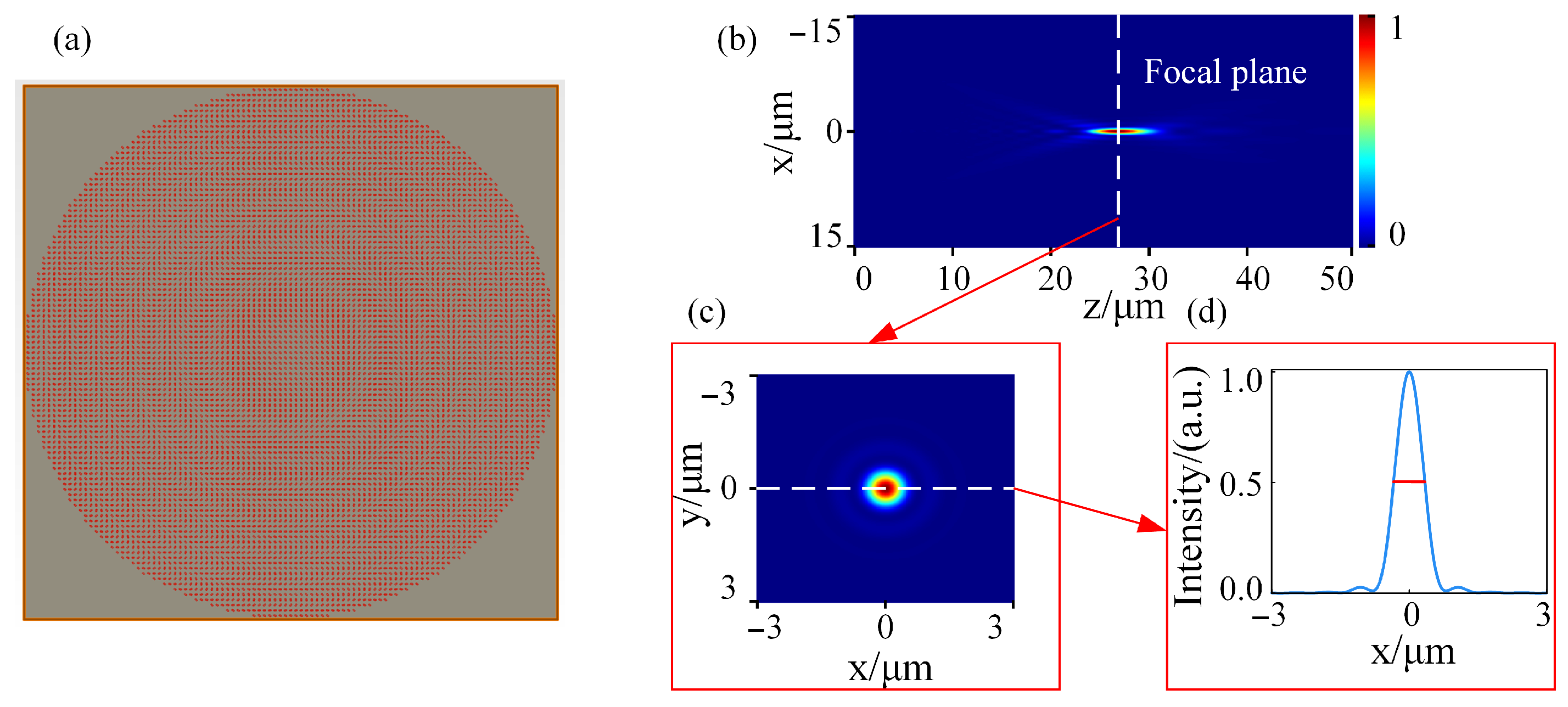
The phase distribution obtained through Equation (9) is shown in Figure 3b. To verify the accuracy of the derived phase distribution, the commercial simulation software Lumerical FDTD 2024R1 is employed. This software utilizes the finite-difference time-domain (FDTD) numerical method, which enables precise solutions of electromagnetic field distributions governed by Maxwell’s equations. Its operational principle involves discretizing space and time domains, followed by iterative calculations of electromagnetic field evolution in the time domain to capture wave propagation, scattering, and reflection phenomena.The key advantage lies in its ability to accurately simulate electromagnetic wave propagation through metalenses featuring subwavelength structures, making it widely applicable in metalens and metamaterial research. Using this FDTD software, a metalens model with a preset focal length F o f f s e t = 30 μm is established, as illustrated in Figure 4a. This model comprises a 30 × 30 μm metalens array with a SiO2 substrate and silicon (Si) nano-pillars designed according to the previously optimized data. The corresponding simulation results are presented in Figure 4b–d.
Figure 4b confirms that the metalens phase distribution derived from Equation (9) produces a well-defined, high-intensity focal spot precisely near the intended focal length F o f f s e t . Figure 4c,d show that the spot breaks the diffraction limit, with FWHM = 0.6834 < σ = 0.8499 according to Equation (10). Taken together, these results demonstrate that the phase distribution given by Equation (8) faithfully reconstructs the outcome of the inverse diffraction process.
σ = 0.61 λ N A

2.4. Design of Fresnel-Based Moiré Varifocal Metalens

Based on the Fresnel framework, the Moiré metalens is redesigned by incorporating the derived Fresnel phase to address the limitations of TMVLs. Firstly, the focal length f in Equation (8) is rescaled to vary continuously from F o f f s e t to F o f f s e t /3, corresponding to a relative rotation angle θ that varies from 0 to 2 π . A linear mapping between θ and f yields Equation (11).
f = F o f f s e t F o f f s e t 3 π · θ
The term π R 2 / λ f in Equation (8) contains f in the denominator, and substituting the reciprocal of Equation (11) would yield a phase term inversely proportional to θ . However, since the Moiré metalens phase function cannot accommodate θ in the denominator, a linear approximation is required. By applying the same linear mapping approach used in Equation (11), a linear relationship between 1/f and θ is established, as expressed in Equation (12).
1 f = 1 F o f f s e t + 1 π · F o f f s e t · θ
If we substitute Equations (11) and (12) into Equation (8), the following formula is obtained:
Φ = k · F o f f s e t + π r 2 λ · F o f f s e t k · F o f f s e t 3 π r 2 λ · F o f f s e t · θ
This procedure establishes a direct relationship between the Fresnel phase distribution and the rotation angle θ . In Equation (13), the factor containing θ is referred to as the dynamic term, while the remaining portion—identical to Equation (9)—is defined as the static term, as it is independent of θ . By leveraging the properties of the Moiré metalens and using Equation (13), Equation (13) can be treated as the combined phase distribution of the two Moiré metalenses. The individual phase distributions are then obtained through a back-calculation process, resulting in Equation (14).
Φ 1 = k · F o f f s e t 3 π r 2 λ · F o f f s e t · φ + k · F o f f s e t 2 + π r 2 2 λ F o f f s e t Φ 2 = k · F o f f s e t 3 π r 2 λ · F o f f s e t · φ + k · F o f f s e t 2 + π r 2 2 λ F o f f s e t
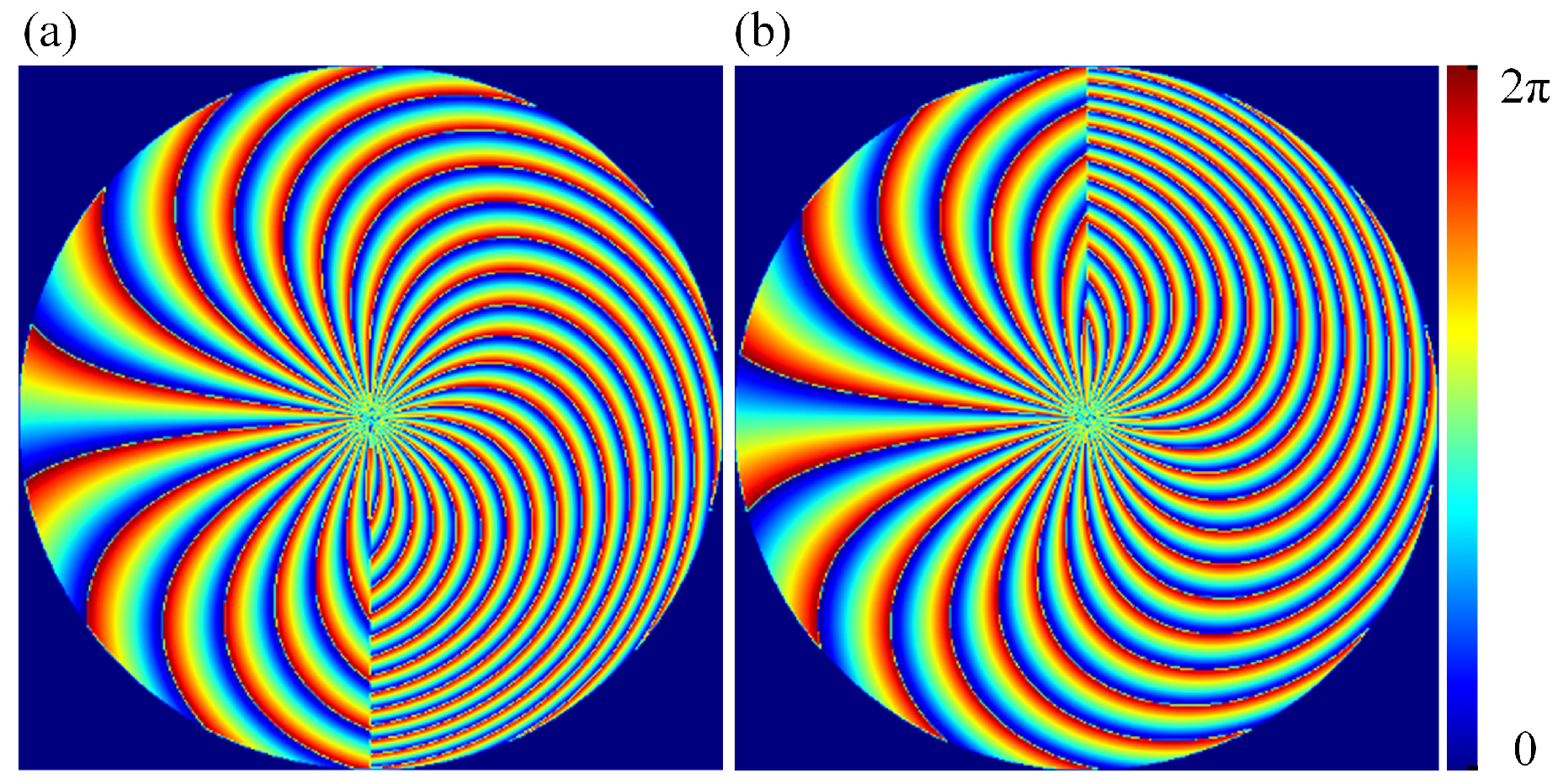
According to Equation (14), by setting r = 15 μm and F o f f s e t = 30 μm, the phase distribution diagram of the two Moiré lenses can be obtained, as shown in Figure 5.
Figure 5 reveals a dense concentration of phase contours near the lens center. This characteristic arises from the term k F o f f s e t φ /3 π in Equation (14) and corresponds to a phase shifter whose phase distribution is shown in Figure 6.
In practice, the phase on the metalens is realized by the nano-unit array. If the phase pattern is too dense, the nano-units cannot reproduce it accurately and the overall phase distribution is compromised. To remove this effect, the term k F o f f s e t /3 π in Equation (14) is removed to obtain Equation (15).
Φ 1 = r 2 λ · F o f f s e t · φ + k · F o f f s e t 2 + π r 2 2 λ F o f f s e t Φ 2 = r 2 λ · F o f f s e t · φ + k · F o f f s e t 2 + π r 2 2 λ F o f f s e t
Using Equation (15), a new phase distribution is derived, as illustrated Figure 7.
Consequently, the transmission functions T1 and T2 for the Moiré varifocal metalens are obtained as shown in Equation (16).
T 1 = e i r 2 λ F o f f s e t · φ + k F o f f s e t 2 + π r 2 2 λ F o f f s e t T 2 = e i r 2 λ F o f f s e t · φ + k F o f f s e t 2 + π r 2 2 λ F o f f s e t
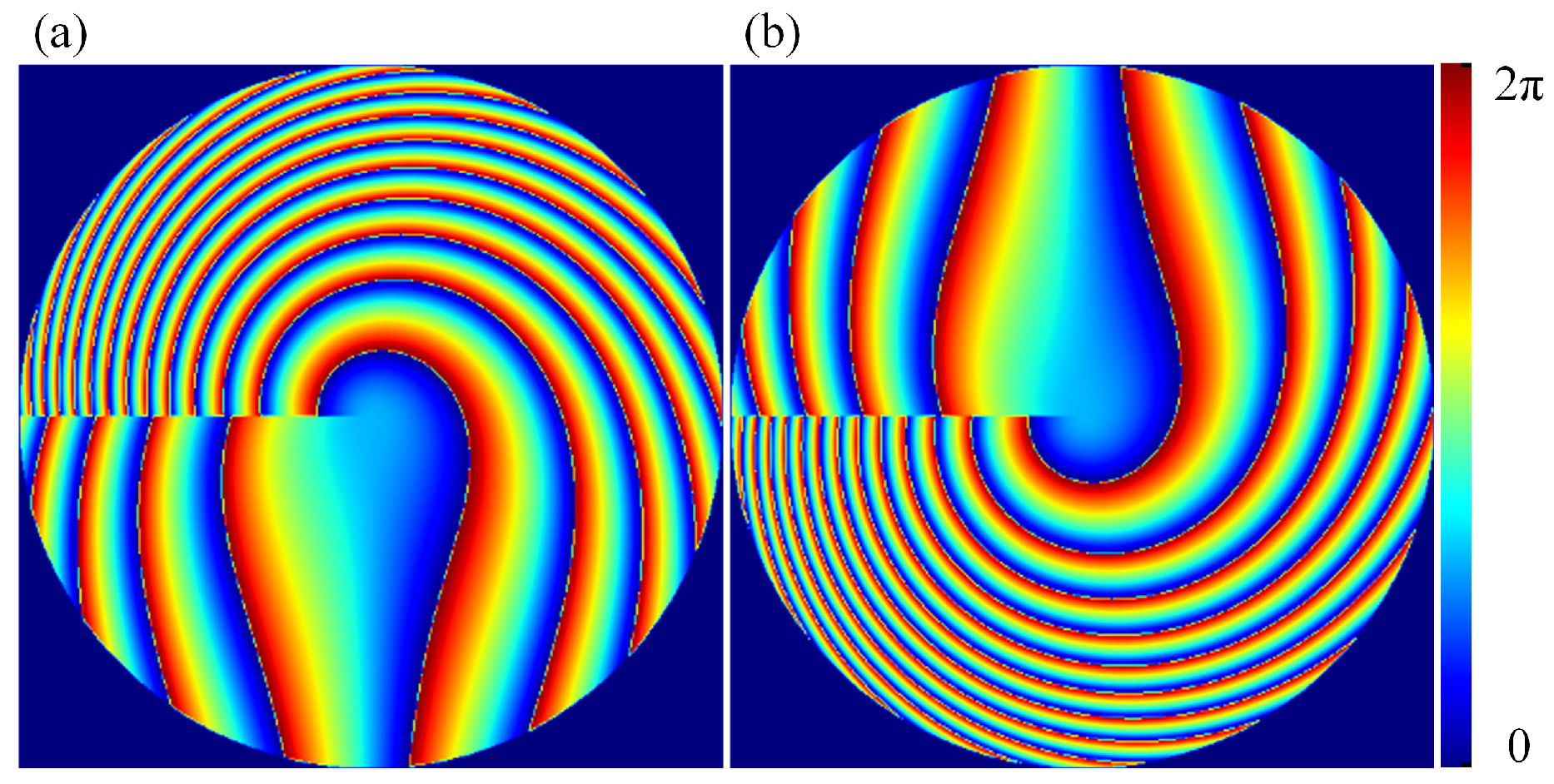
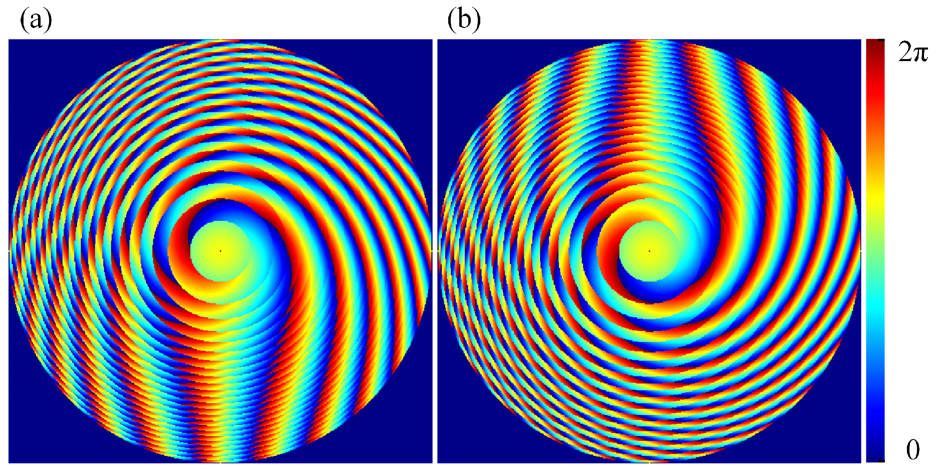
Owing to an inherent drawback of rotational varifocal Moiré metalenses, the phase distribution obtained from Equation (16) exhibits sector-like discontinuities. To remove these sectors, a rounding function was applied to the dynamic term in Equation (16), thus ensuring phase continuity. The final transmission functions of the Modified Moiré varifocal metalenses (MMVLs) based on the Fresnel principle are shown in Equation (17).
T 1 = e i r o u n d ( r 2 λ F o f f s e t ) · φ + k F o f f s e t 2 + π r 2 2 λ F o f f s e t T 2 = e i r o u n d ( r 2 λ F o f f s e t ) · φ + k F o f f s e t 2 + π r 2 2 λ F o f f s e t
Using the refined Equation (17), the final phase distribution of the MMVLs is obtained, as shown in Figure 8.
Furthermore, to obtain the relationship between the focal length and the rotation angle θ , the following Equation (18) can be derived based on Equation (13).
k f = k · F o f f s e t k · F o f f s e t 3 π · θ π r 2 λ f = π r 2 λ · F o f f s e t + r 2 λ · F o f f s e t · θ
Moreover, since the k F o f f s e t θ / 3 π term generates a dense phase distribution at the center of the metalens, this term related to the angle θ has been removed from the transfer function of MMVLs. Then, the term of equation k f in Equation (18) cannot represent the relationship between focal length f and angle θ . Therefore, this paper uses Equation (19) to express the relationship between focal length f and angle θ .
π r 2 λ f = π r 2 λ · F o f f s e t + r 2 λ · F o f f s e t · θ
From Equation (19), the relationship between f and θ is simplified as follows:
f θ = π · F o f f s e t π + θ

3. Results and Discussion

Prior work [43] shows that a Moiré metalens consists of a pair of mutually complex-conjugate elements, whose phase functions must satisfy the relation Equation (21).
Φ 1 r 1 , φ 1 = Φ 2 r 2 , φ 2
This property requires that the two constituent metalenses exhibit identical spatial phase distributions with opposite signs. Consequently, inverting one metalens and placing it face-to-face with the other forms the complete Moiré pair, implying that only a single phase distribution needs to be determined. However, phase information alone is insufficient. Since geometric phase control is employed, the rotational angle θ of each nano-pillar must be specified. Under ideal conditions with perfect polarization conversion efficiency [54], the relation φ = 2 θ holds. In practical applications, this ideal efficiency is challenging to achieve with nano-pillars. Therefore, a phase-to-rotation mapping relationship is established to correlate experimentally measured phase values with required rotation angles. This continuous correspondence suffices to precisely determine the nano-pillar orientations across the entire Moiré metalens.
Based on the phase-rotation relationship library illustrated in Figure 2b, a comparative investigation of focal quality and varifocal performance was conducted between the MMVLs and TMVLs. For this purpose, simulation models for both Moiré metalenses were established using commercial Lumerical FDTD software. To ensure consistent comparison, nano-pillars in both models employed the previously optimized design, with SiO2 substrates and silicon (Si) nano-pillars. Due to computational resource and simulation time constraints, all experiments in this paper were validated using small-scale models with Moiré metalens sized at 18 × 18 μm, incorporating Perfectly Matched Layer (PML) boundary conditions. Since the transmission function of the Moire metalens itself requires no optimization, the transmission function of the Moire varifocal metalens remains applicable for larger dimensions when the incident wavelength λ and focal length F o f f s e t are predetermined. For any required wavelength, dimensions, and focal length, phase distributions for larger-scale Moiré varifocal metalenses can be directly calculated using this transmission function, thus enabling the design of larger-scale Moire lenses.
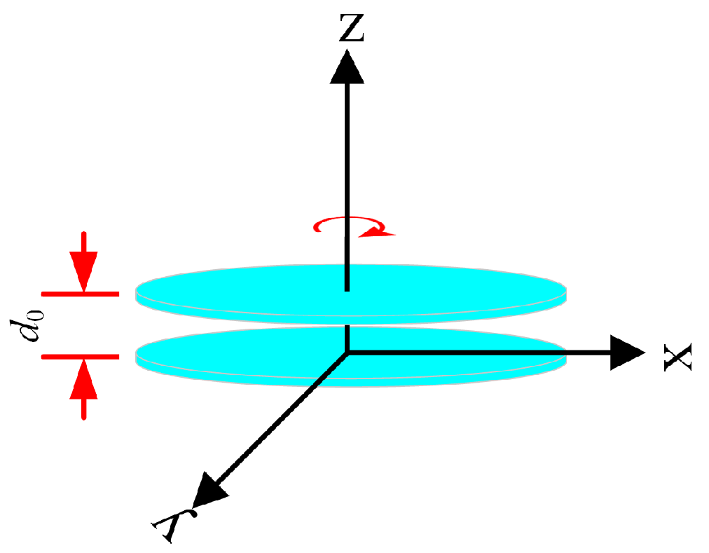
According to Equation (17), the two metalenses should ideally be aligned with their phase distributions centered on the same axis and separated by zero axial distance, meaning that they touch along the optical axis. In practice, however, the presence of nano-pillars requires a small gap d 0 to prevent mechanical wear during rotation. Excessive separation introduces diffraction errors that shift the combined phase distribution away from the intended design, causing the focal spot to deviate off-axis and reducing efficiency. To ensure that the first metalens diffracts the field onto the corresponding pixels of the second, the separation d 0 must remain below twice the Talbot distance [45], as shown in Equation (22).
d 0 < 1 2 D T a l b o t = P 2 λ
d 0 denotes the axial separation between the two metalenses, P is the nano-unit period, and λ is the incident wavelength. Using the previously optimized nano-pillar parameters, d 0 is set to approximately 150 nm. The resulting schematic of the two Moiré metalenses is shown in Figure 9.

3.1. Varifocal Experiment

The physical characteristics of TMVLs prevent their varifocal range from being tailored to practical demands. Theoretically, the varifocal range spans from 0° to +, where “+” originates from the absence of a discernible focal spot at the 0° rotation angle, namely non-existent focus. Owing to experimental constraints, a small-scale model is employed for the comparative evaluation of the both types of metalenses. In such a compact device, the focal position cannot be set significantly beyond the physical size of the metalens without risking a lost or misplaced focus. Consequently, the effective varifocal range for the miniature TMVLs is limited to roughly two to three times the metalens diameter. To enable a fair comparison, the preset focal offset F o f f s e t for MMVLs is therefore set at 30 μm.
To compare the focal spot quality between MMVLs and TMVLs during varifocal tuning, full 360° rotation simulations were conducted using Lumerical FDTD. Figure 10, Figure 11 and Figure 12 show the electric field evolution in both x–z and x–y planes, along with the focusing efficiency curves throughout the focal sweep.
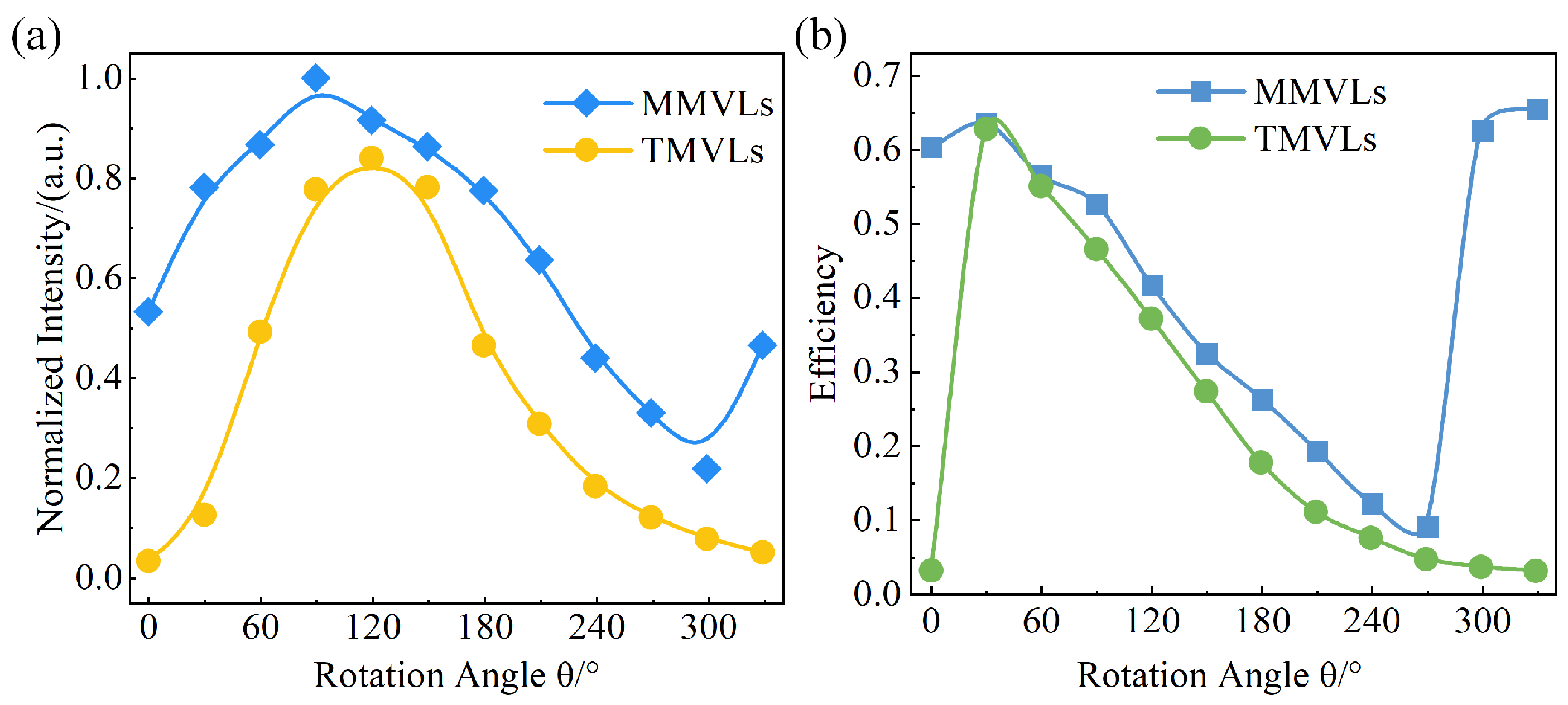
Figure 10 and Figure 11 present the optical intensity distributions of MMVLs and TMVLs at twelve discrete rotation angles, sampled at 30° increments over a full 360° cycle. For TMVLs, no discernible focus is observed at 0° due to inherent limitations, and the focal spot exhibits off-axis drift along with significant quality degradation throughout rotation. Figure 12a compares normalized intensities (both scaled to MMVLs’ peak intensity), revealing that TMVLs experience intensity variations exceeding 60% between 30°and 120°, and approximately 45% between 120° and 210°. In contrast, MMVLs produce a distinct focus at the preset F o f f s e t at 0° and maintain well-defined focal spots with stable shapes at all angles. Notably, as the dynamic term progressively weakens with increasing rotation angle—a trend also observed in TMVLs—MMVLs undergo focal switching near 270°, where energy transfers progressively from the short-focus spot to the long-focus spot until the former vanishes. This switching recurs cyclically. Additionally, MMVL generates foci beyond the design focal range at 300° (−60°) and 330° (−30°). These phenomena arise from the inherent sector issue in rotationally tuned moiré metalenses. Although rounding the transmission function (Equation (17)) ensures continuity, it cannot fully eliminate the influence of the sector phase. Beyond 270°, the sector phase gradually supersedes the ideal target focus phase plane, resulting in extraneous foci outside the intended focal range.
As shown in Figure 12a, the MMVLs exhibit higher optical intensity than the TMVLs at all angles. Within the 30°–210° range, the MMVL intensity fluctuates within a 25% variation margin. Figure 12b plots the focusing efficiency versus rotation angle for both metalenses. Although efficiency variations occur in both systems due to the dynamic term, the MMVLs demonstrate superior overall focusing efficiency compared to the TMVLs, with significant improvements in focal quality at extreme angles (such as 0° and 330°).
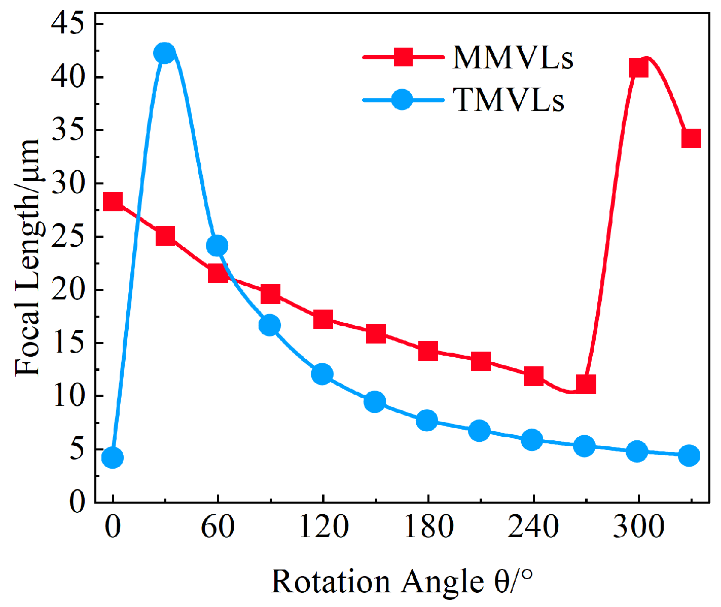
Figure 13 presents variations in focal length f versus rotational angle θ for both metalens types during varifocal operation. The blue curve indicates significant fluctuations in TMVLs, with a focal length reduction approaching 30 μm before 120° accompanied by substantial intensity variations as shown in Figure 12a. This observation aligns with known limitations of TMVLs. In contrast, MMVLs exhibit relatively gradual variation. At around 270°, focal switching occurs, enabling MMVLs to achieve focus beyond the preset focal length range and gain a new focal range. As shown in Figure 12a, the light intensity reaches 30% of the peak intensity after 270°, thereby expanding the effective varifocal range of MMVLs.
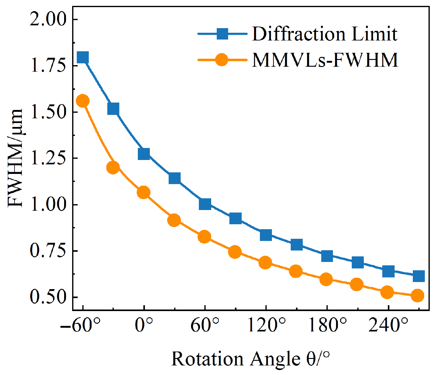
Figure 14 presents the angular dependence of MMVLs’ FWHM across a full rotation. At every angle, the value breaks the diffraction limit (0.61 λ /NA), achieving super-diffraction-limited focusing. Consequently, Figure 10, Figure 11, Figure 12, Figure 13 and Figure 14 verify MMVLs’ comprehensive superiority over TMVLs. The MMVLs, based on a Fresnel modified design, not only resolve the absence of focus at 0° observed in TMVLs but also significantly reduce focal quality fluctuations during varifocal tuning.

3.2. Robustness Analysis

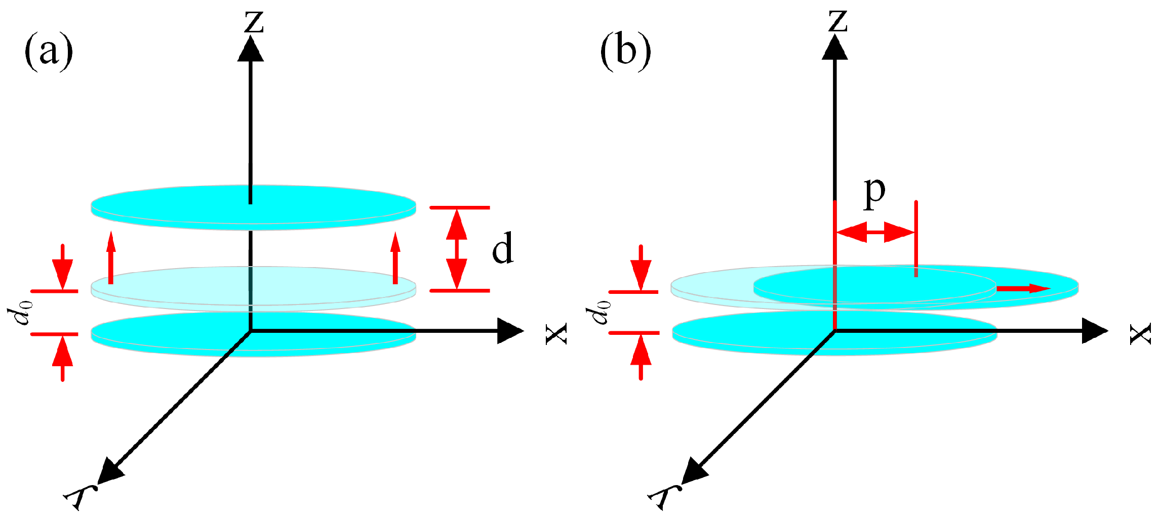
As established in prior discussions, an inter-metalens separation distance d 0 is specified to prevent frictional damage between nano-pillars. However, deviations from the designed d 0 are inevitable during practical assembly. Such mounting-induced distance errors introduce phase distortion through diffraction effects, thereby degrading the focusing performance of Moiré metalenses. Similarly, phase distortion also arises when the metalens is misaligned from the optical axis, as shown in Figure 15. To investigate the impact of axial distance error d and off-center error p on the robustness of varifocal metalenses, parametric simulations are conducted by systematically varying d and p.
To analyze the impact of axial distance d on Moiré metalenses, the methodology from earlier sections is adopted. MMVL and TMVL lens-pair models with 18 μm diameters are constructed using FDTD simulations. The axial separation d is progressively offset from the design spacing d 0 to 20 d 0 (0–3 μm) in 2 d 0 increments. For each offset, electric field distributions in x–z and x–y planes are simulated to evaluate the focusing stability under axial separation changes. To enable direct comparison, the rotation angle was fixed at θ = 120°—corresponding to the peak intensity angle in Figure 12a—with spatial field distributions acquired for both systems.
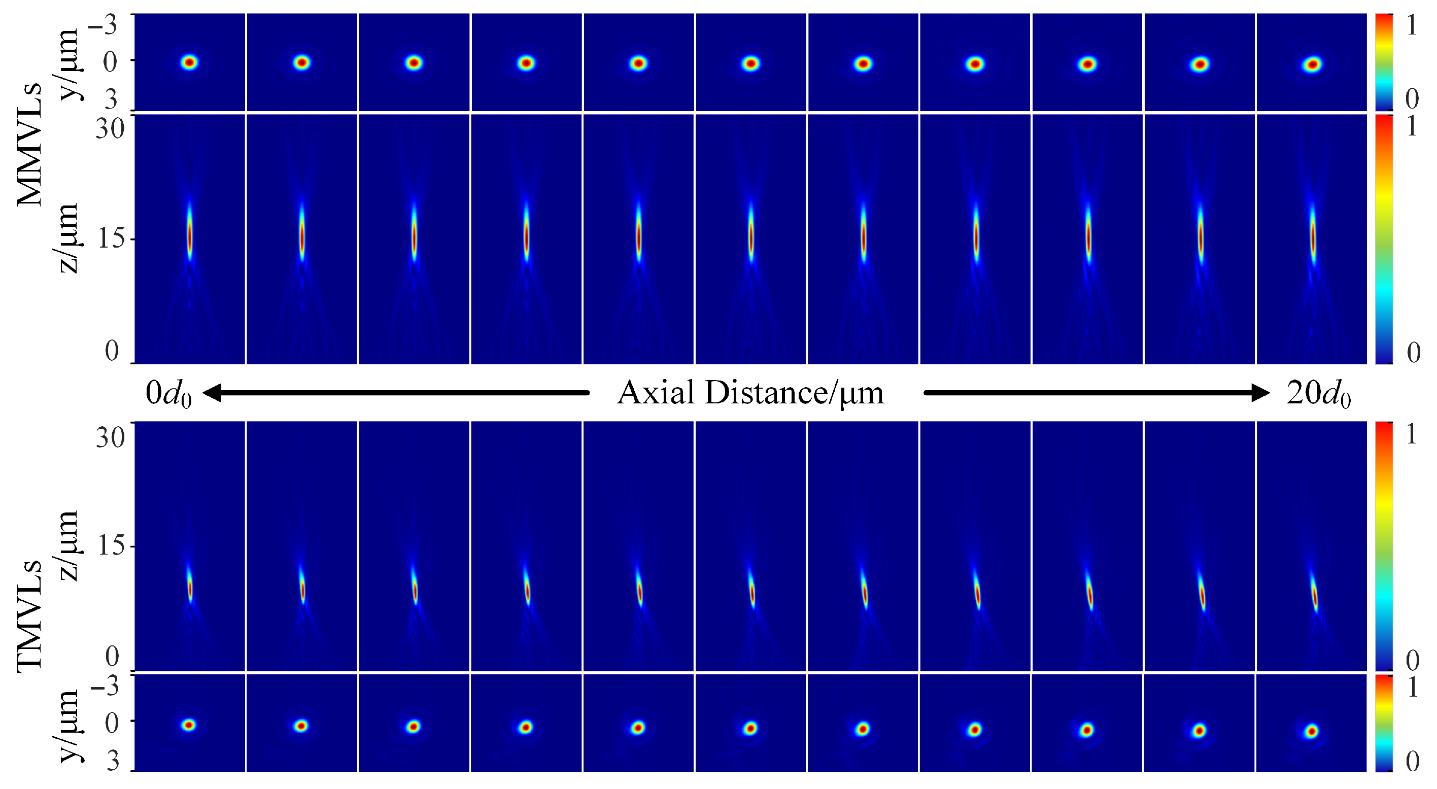
The performance differences between MMVLs and TMVLs under varying axial distance d were determined through the FDTD simulation. Figure 16 clearly illustrates the impact of d on both systems, displaying x–z and x–y plane field distributions at eleven discrete sampling points from 0 to 20 d 0 with 2 d 0 intervals. As evidenced in the upper row (MMVLs), the focal spot maintains excellent shape integrity throughout 0 to 20 d 0 , showing no visible change. Conversely, TMVLs (lower row) exhibit significant degradation. Beyond 4 d 0 (≈0.6 μm), the focal point of the TMVLs deviates off-axis, with the off-axis distance increasing monotonically with d. At 20 d 0 (≈3 μm), this distance exceeds ≈0.5 μm.
Figure 17 compares the normalized intensity and focusing efficiency of the two metalenses. For MMVLs, the intensity decreases marginally: at 10 d 0 (≈1.5 μm), it drops to 87% of the pre-variation value, and at 20 d 0 (≈3 μm), to 76%, and its focusing efficiency remains above 37% throughout the 20 d 0 range. Moreover, TMVLs exhibit severe intensity degradation, plunging to 80% at 4 d 0 (≈0.6 μm) and further declining to 67% at 20 d 0 .
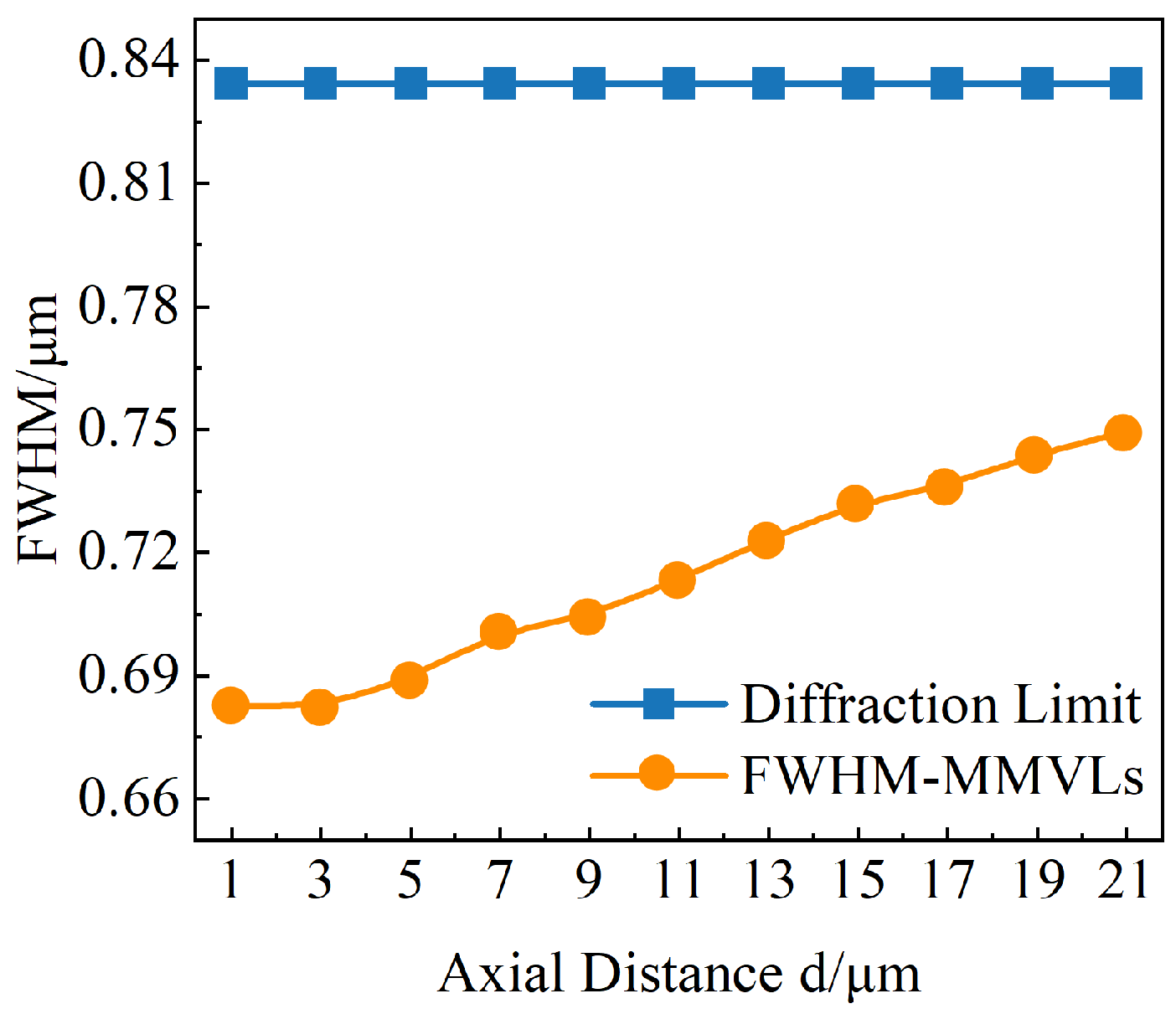
The FWHM variations presented in Figure 18 demonstrate that MMVLs maintain FWHM fluctuations within 0.1 μm throughout axial distance changes while breaking the diffraction limit.
The results presented in Figure 16, Figure 17 and Figure 18 indicate higher robustness of MMVLs against axial distance variations while maintaining stable focusing performance. In contrast, TMVLs’ focal positions and spot morphology are susceptible to axial distance changes, leading to a degradation in focusing performance.
This phenomenon arises from the sensitivity of TMVLs’ a r 2 φ term to axial distance d. As d increases, the phase modulation imparted on the first metalens fails to diffract accurately onto the second metalens, thereby disrupting the composite phase distribution and leading to progressive beam divergence. In contrast, the static phase term in MMVLs is largely insensitive to variations in d, preserving its functional stability. As a result, the static phase distribution of MMVLs significantly enhances axial robustness, offering markedly improved tolerance to axial displacements compared to TMVLs. This ensures reliable adaptation to structural variations in practical applications while sustaining stable focusing performance.
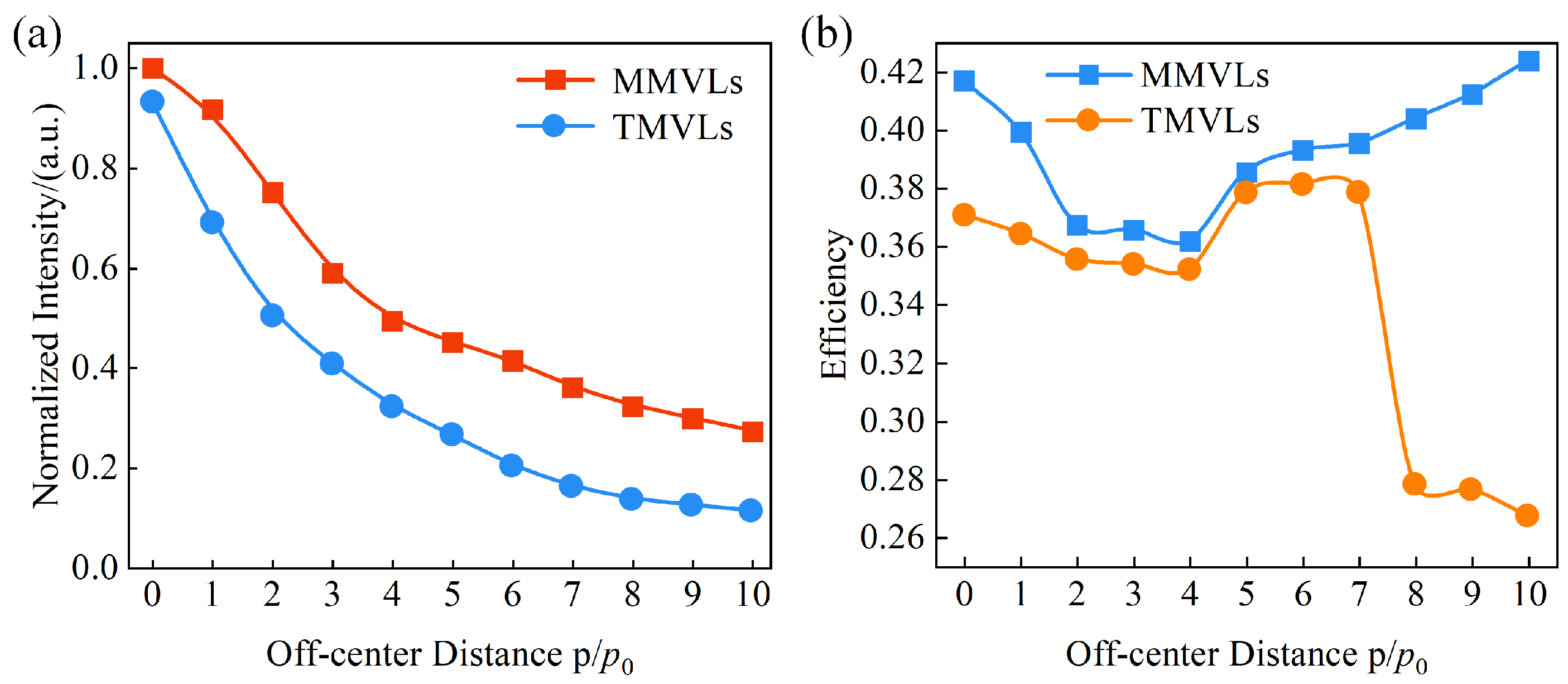
Furthermore, phase distribution symmetry proves critical for maintaining focusing performance in Moiré metalens design. Off-center error p severely disrupts this symmetry, causing significant performance degradation. To analyze the impact of p, a methodology analogous to the axial distance d investigation was employed. With p 0 = 2 d 0 = 300 nm defined as the unit offset, one metalens was laterally displaced along the x-axis while fixing the other. Spatial field distributions were simulated for transverse eccentricities ranging from 0 to 10 p 0 (0–3 μm), with the rotation angle fixed at θ = 120°.
Figure 19 compares the x–y and x–z plane field distributions of both moiré metalenses under varying transverse eccentricity p, further elucidating centering error impacts. For MMVLs, focal spot deformation initiates at 4 p 0 (≈1.2 μm) and intensifies with increasing x-axis offset. Crucially, visually discernible foci persist in x–z planes, confirming the retention of fundamental focusing functionality. Conversely, TMVLs exhibit spot deformation from 3 p 0 (≈0.9 μm), with progressively accelerating morphological degradation. At 8 p 0 (≈2.4 μm), the severe off-axis deviation reaches 2.7 μm. In x–z projections, the focal definition degrades beyond recognition at 6 p 0 (≈1.8 μm), manifesting focal degradation.
As shown in Figure 20, MMVLs’ focal intensity undergoes a significant decline to 48% of its pre-eccentricity value at 5 p 0 (≈1.5 μm), with the focusing efficiency dropping to ≈38%. However, the efficiency consistently remains above 36% throughout the entire eccentricity process. In contrast, TMVLs exhibit a pronounced performance degradation at merely 3 p 0 (≈0.9 μm)—the intensity plunges to 40%, while the focus efficiency displays substantial fluctuations, as shown in Figure 20b.
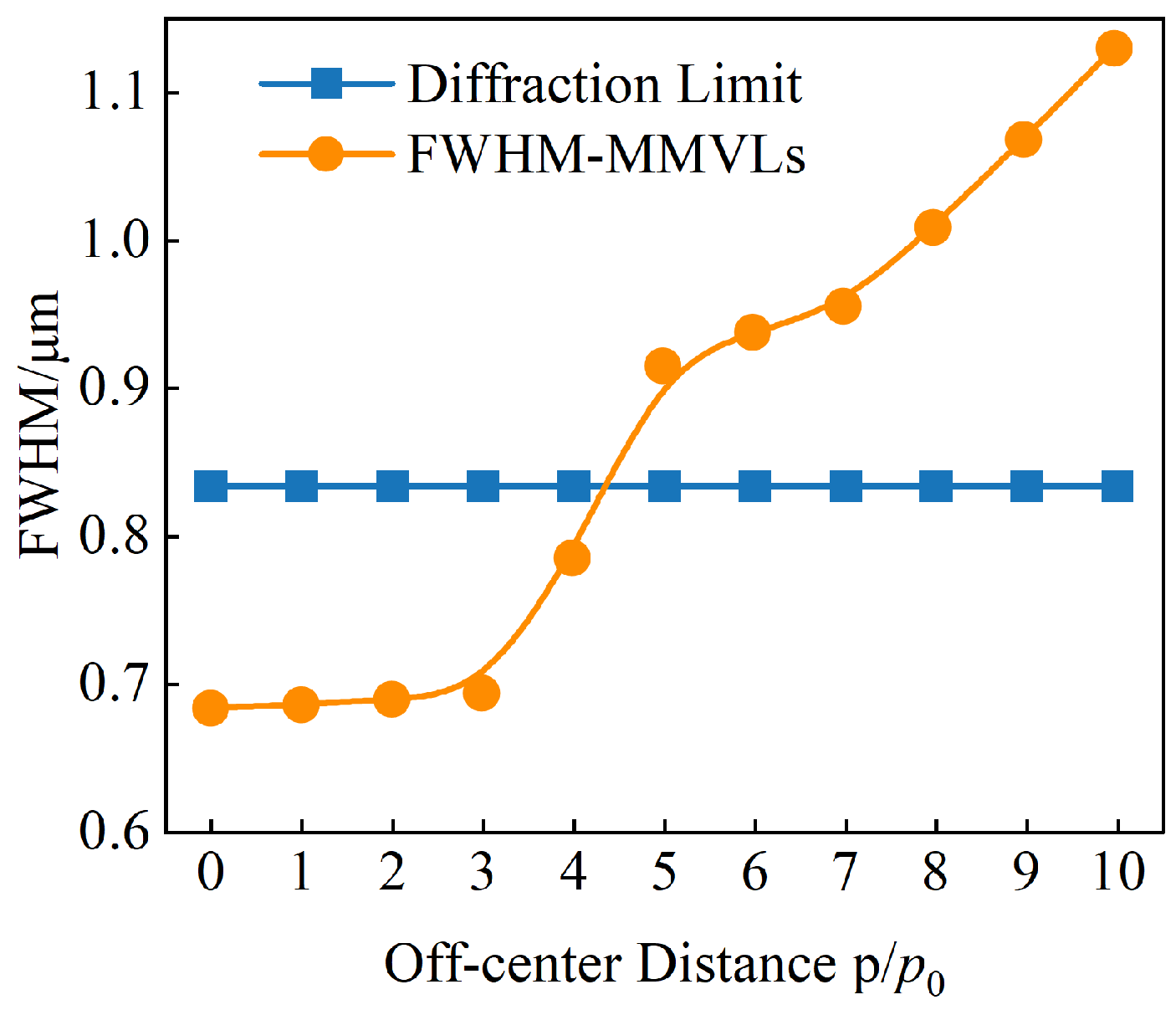
Figure 21 shows that the F W H M of MMVLs remains super-diffraction-limited at an off-center distance of 4 p 0 (1.2 μm). However, F W H M progressively exceeds the diffraction limit with increasing off-center distance p.
These results indicate that, although MMVLs exhibit noticeable performance degradation under large off-center displacements, they retain measurable robustness. This divergence stems from fundamental design differences: the static phase component in MMVLs provides inherent tolerance to off-center misalignments, whereas TMVLs, relying solely on the a r 2 φ phase term, are highly susceptible to symmetry deviations. As a result, MMVLs demonstrate significantly greater adaptability to off-center conditions, while TMVLs experience rapid and pronounced performance deterioration with increasing displacement.

4. Conclusions

This paper proposes a modified Moiré varifocal metalens (MMVL) based on Fresnel principles. The Fresnel phase distribution across the target focal range is derived using Fresnel diffraction theory, yielding a phase function linked to the rotation angle. This function serves as the composite phase profile for the Moiré metalens pair, from which the individual phase distributions and corresponding transmission functions for each metalens are obtained. The resulting MMVL design integrates static and dynamic terms: the static term establishes the baseline focusing capability, while the dynamic term enables varifocal tuning across the desired focal range. This approach effectively overcomes TMVLs’ defocusing issues at 0° rotation while improving the significant degradation of focal quality during varifocal operation. Systematic comparative studies demonstrate that MMVLs eliminate inherent defocusing in TMVLs and enhance focal quality throughout rotational cycles. In terms of robustness, the MMVLs demonstrate superior stability under axial displacement and exhibit enhanced tolerance to lateral misalignment. These characteristics enable more stable optical performance in practical applications, particularly in the presence of symmetry errors introduced during fabrication and assembly. As such, the proposed MMVL design holds strong potential for applications in microscopic imaging and optical tweezers.

Author Contributions

Conceptualization and methodology, D.C., X.L. and L.Z.; software and validation, D.C. and S.S.; investigation and data curation, D.C., X.L. and L.Z.; writing—original draft preparation, D.C. and S.S.; writing—review and editing, X.L. and L.Z. All authors have read and agreed to the published version of the manuscript.

Funding

This research was funded by ZSTU, China, grant number 11162832612201.

Institutional Review Board Statement

Not applicable.

Informed Consent Statement

Not applicable.

Data Availability Statement

The data are contained within the article.

Conflicts of Interest

The authors declare no conflicts of interest.

References

  1. Drexler, W.; Morgner, U.; Ghanta, R.K.; Kärtner, F.X.; Schuman, J.S.; Fujimoto, J.G. Ultrahigh-resolution ophthalmic optical coherence tomography. Nat. Med. 2001, 7, 502–507. [Google Scholar] [CrossRef] [PubMed]
  2. Wang, T.D.; Mandella, M.J.; Contag, C.H.; Kino, G.S. Dual-axis confocal microscope for high-resolution in vivo imaging. Opt. Lett. 2003, 28, 414–416. [Google Scholar] [CrossRef]
  3. Fujimoto, J.G. Optical coherence tomography for ultrahigh resolution in vivo imaging. Nat. Biotechnol. 2003, 21, 1361–1367. [Google Scholar] [CrossRef]
  4. Ge, X.; Chen, S.; Chen, S.; Liu, L. High resolution optical coherence tomography. J. Light. Technol. 2021, 39, 3824–3835. [Google Scholar] [CrossRef]
  5. Mazlin, V.; Xiao, P.; Dalimier, E.; Grieve, K.; Irsch, K.; Sahel, J.A.; Fink, M.; Boccara, A.C. In vivo high resolution human corneal imaging using full-field optical coherence tomography. Biomed. Opt. Express 2018, 9, 557–568. [Google Scholar] [CrossRef]
  6. Marini, M.; Nardini, A.; Martínez Vázquez, R.; Conci, C.; Bouzin, M.; Collini, M.; Osellame, R.; Cerullo, G.; Kariman, B.; Farsari, M.; et al. Microlenses fabricated by two-photon laser polymerization for cell imaging with non-linear excitation microscopy. Adv. Funct. Mater. 2023, 33, 2213926. [Google Scholar] [CrossRef]
  7. Wang, Y.; Zhang, X.; Xu, J.; Sun, X.; Zhao, X.; Li, H.; Liu, Y.; Tian, J.; Hao, X.; Kong, X.; et al. The development of microscopic imaging technology and its application in micro-and nanotechnology. Front. Chem. 2022, 10, 931169. [Google Scholar] [CrossRef] [PubMed]
  8. Kumar, S.; Yang, D. Application of time lenses for high speed fiber-optic communication systems. In Proceedings of the 2009 4th International Conference on Computers and Devices for Communication (CODEC), Kolkata, India, 14–16 December 2009; IEEE: Washington, DC, USA, 2009; pp. 1–6. [Google Scholar]
  9. Tian, J.; Guo, T.; He, N.; Du, J.; Huang, Q.; Hong, X.; Fei, C.; Wang, Y.; Zhang, T.; Zhang, J.; et al. Wide-field-of-view modulating retro-reflector system based on a telecentric lens for high-speed free-space optical communication. IEEE Photonics J. 2023, 15, 1–8. [Google Scholar] [CrossRef]
  10. Enger, J.; Goksör, M.; Ramser, K.; Hagberg, P.; Hanstorp, D. Optical tweezers applied to a microfluidic system. Lab A Chip 2004, 4, 196–200. [Google Scholar] [CrossRef]
  11. Fällman, E.; Schedin, S.; Jass, J.; Andersson, M.; Uhlin, B.E.; Axner, O. Optical tweezers based force measurement system for quantitating binding interactions: System design and application for the study of bacterial adhesion. Biosens. Bioelectron. 2004, 19, 1429–1437. [Google Scholar] [CrossRef]
  12. Homburg, O.; Hauschild, D.; Kubacki, F.; Lissotschenko, V. Efficient beam shaping for high-power laser applications. In Proceedings of the Laser Source and System Technology for Defense and Security II, Kissimmee, FL, USA, 17–18 April 2006; SPIE: Philadelphia, PA, USA, 2006; Volume 6216, pp. 48–55. [Google Scholar]
  13. Laskin, A.; Kaiser, P.; Laskin, V.; Ostrun, A. Laser beam shaping for biomedical microscopy techniques. In Proceedings of the Biophotonics: Photonic Solutions for Better Health Care V, Brussels, Belgium, 4–7 April 2016; SPIE: Philadelphia, PA, USA, 2016; Volume 9887, pp. 251–260. [Google Scholar]
  14. Kubby, J.A. Adaptive Optics for Biological Imaging; CRC Press: Boca Raton, FL, USA, 2013. [Google Scholar]
  15. Hampson, K.M.; Turcotte, R.; Miller, D.T.; Kurokawa, K.; Males, J.R.; Ji, N.; Booth, M.J. Adaptive optics for high-resolution imaging. Nat. Rev. Methods Prim. 2021, 1, 68. [Google Scholar] [CrossRef] [PubMed]
  16. Gaunekar, A.S.; Widdowson, G.P.; Srikanth, N.; Guangneng, W. Design and development of a high precision lens focusing mechanism using flexure bearings. Precis. Eng. 2005, 29, 81–85. [Google Scholar] [CrossRef]
  17. Dadkhah, A.; Jiao, S. Optical coherence tomography-guided dynamic focusing for combined optical and mechanical scanning multimodal photoacoustic microscopy. J. Biomed. Opt. 2019, 24, 121906. [Google Scholar] [CrossRef]
  18. Li, H.; Chen, H.; Li, X.; Song, H.; Wang, D. Structural optical design of multi-group, high zoom ratio optical systems. Opt. Commun. 2024, 551, 130022. [Google Scholar] [CrossRef]
  19. Ren, H.; Wu, S.T. Variable-focus liquid lens. Opt. Express 2007, 15, 5931–5936. [Google Scholar] [CrossRef] [PubMed]
  20. Pan, M.; Fu, Y.; Zheng, M.; Chen, H.; Zang, Y.; Duan, H.; Li, Q.; Qiu, M.; Hu, Y. Dielectric metalens for miniaturized imaging systems: Progress and challenges. Light. Sci. Appl. 2022, 11, 195. [Google Scholar] [CrossRef]
  21. Liu, X.; Starr, T.; Starr, A.F.; Padilla, W.J. Infrared spatial and frequency selective metamaterial with near-unity absorbance. Phys. Rev. Lett. 2010, 104, 207403. [Google Scholar] [CrossRef]
  22. Yu, N.; Genevet, P.; Kats, M.A.; Aieta, F.; Tetienne, J.P.; Capasso, F.; Gaburro, Z. Light propagation with phase discontinuities: Generalized laws of reflection and refraction. Science 2011, 334, 333–337. [Google Scholar] [CrossRef] [PubMed]
  23. Grady, N.K.; Heyes, J.E.; Chowdhury, D.R.; Zeng, Y.; Reiten, M.T.; Azad, A.K.; Taylor, A.J.; Dalvit, D.A.; Chen, H.T. Terahertz metamaterials for linear polarization conversion and anomalous refraction. Science 2013, 340, 1304–1307. [Google Scholar] [CrossRef] [PubMed]
  24. Zheng, G.; Mühlenbernd, H.; Kenney, M.; Li, G.; Zentgraf, T.; Zhang, S. Metasurface holograms reaching 80% efficiency. Nat. Nanotechnol. 2015, 10, 308–312. [Google Scholar] [CrossRef]
  25. Ren, M.X.; Wu, W.; Cai, W.; Pi, B.; Zhang, X.Z.; Xu, J.J. Reconfigurable metasurfaces that enable light polarization control by light. Light. Sci. Appl. 2017, 6, e16254. [Google Scholar] [CrossRef]
  26. Xiao, X.; Zhao, Y.; Ye, X.; Chen, C.; Lu, X.; Rong, Y.; Deng, J.; Li, G.; Zhu, S.; Li, T. Large-scale achromatic flat lens by light frequency-domain coherence optimization. Light. Sci. Appl. 2022, 11, 323. [Google Scholar] [CrossRef] [PubMed]
  27. Han, Y.; Lu, X.; Lv, H.; Mou, Z.; Zhou, C.; Teng, S. Bifocal metalens with diverse polarization combination. Plasmonics 2021, 16, 575–579. [Google Scholar] [CrossRef]
  28. Khorasaninejad, M.; Chen, W.T.; Devlin, R.C.; Oh, J.; Zhu, A.Y.; Capasso, F. Metalenses at visible wavelengths: Diffraction-limited focusing and subwavelength resolution imaging. Science 2016, 352, 1190–1194. [Google Scholar] [CrossRef] [PubMed]
  29. Shalaginov, M.Y.; An, S.; Zhang, Y.; Yang, F.; Su, P.; Liberman, V.; Chou, J.B.; Roberts, C.M.; Kang, M.; Rios, C.; et al. Reconfigurable all-dielectric metalens with diffraction-limited performance. Nat. Commun. 2021, 12, 1225. [Google Scholar] [CrossRef] [PubMed]
  30. Afridi, A.; Canet-Ferrer, J.; Philippet, L.; Osmond, J.; Berto, P.; Quidant, R. Electrically driven varifocal silicon metalens. Acs Photonics 2018, 5, 4497–4503. [Google Scholar] [CrossRef]
  31. Yang, F.; Dao, K.P.; An, S.; Qiu, X.; Zhang, Y.; Hu, J.; Gu, T. Design of continuously tunable varifocal metalenses. J. Opt. 2023, 25, 115102. [Google Scholar] [CrossRef]
  32. Chen, K.; Feng, Y.; Monticone, F.; Zhao, J.; Zhu, B.; Jiang, T.; Zhang, L.; Kim, Y.; Ding, X.; Zhang, S.; et al. A reconfigurable active Huygens’ metalens. Adv. Mater. 2017, 29, 1606422. [Google Scholar] [CrossRef]
  33. Huang, Z.; Hu, B.; Liu, W.; Liu, J.; Wang, Y. Dynamical tuning of terahertz meta-lens assisted by graphene. J. Opt. Soc. Am. B 2017, 34, 1848–1854. [Google Scholar] [CrossRef]
  34. Huang, P.S.; Chu, C.H.; Huang, S.H.; Su, H.P.; Tanaka, T.; Wu, P.C. Varifocal metalenses: Harnessing polarization-dependent superposition for continuous focal length control. Nano Lett. 2023, 23, 10432–10440. [Google Scholar] [CrossRef]
  35. Wang, M.; Lee, J.S.; Aggarwal, S.; Farmakidis, N.; He, Y.; Cheng, T.; Bhaskaran, H. Varifocal metalens using tunable and ultralow-loss dielectrics. Adv. Sci. 2023, 10, 2204899. [Google Scholar] [CrossRef]
  36. Zhang, J.C.; Yao, J.; Tsai, D.P. Meta-lens based on multi-level phase-change. J. Appl. Phys. 2024, 136, 053101. [Google Scholar] [CrossRef]
  37. Shen, Y.; Shen, Z.; Wang, Y.; Xu, D.; Hu, W. Electrically tunable terahertz focusing modulator enabled by liquid crystal integrated dielectric metasurface. Crystals 2021, 11, 514. [Google Scholar] [CrossRef]
  38. Bosch, M.; Shcherbakov, M.R.; Won, K.; Lee, H.S.; Kim, Y.; Shvets, G. Electrically actuated varifocal lens based on liquid-crystal-embedded dielectric metasurfaces. Nano Lett. 2021, 21, 3849–3856. [Google Scholar] [CrossRef]
  39. Arbabi, E.; Arbabi, A.; Kamali, S.M.; Horie, Y.; Faraji-Dana, M.; Faraon, A. MEMS-tunable dielectric metasurface lens. Nat. Commun. 2018, 9, 812. [Google Scholar] [CrossRef]
  40. Han, Z.; Colburn, S.; Majumdar, A.; Böhringer, K.F. MEMS-actuated metasurface Alvarez lens. Microsyst. Nanoeng. 2020, 6, 79. [Google Scholar] [CrossRef] [PubMed]
  41. Fan, W.; Liu, X.N.; Zhou, Y.; Zhang, J.; Liu, S.B.; Li, L. Varifocal diffractive lens based on microfluidics. Opt. Lasers Eng. 2024, 174, 107955. [Google Scholar] [CrossRef]
  42. Wei, S.; Cao, G.; Lin, H.; Yuan, X.; Somekh, M.; Jia, B. A varifocal graphene metalens for broadband zoom imaging covering the entire visible region. ACS Nano 2021, 15, 4769–4776. [Google Scholar] [CrossRef] [PubMed]
  43. Bernet, S.; Ritsch-Marte, M. Adjustable refractive power from diffractive moiré elements. Appl. Opt. 2008, 47, 3722–3730. [Google Scholar] [CrossRef] [PubMed]
  44. Bernet, S.; Harm, W.; Ritsch-Marte, M. Demonstration of focus-tunable diffractive Moiré-lenses. Opt. Express 2013, 21, 6955–6966. [Google Scholar] [CrossRef]
  45. Cui, Y.; Zheng, G.; Chen, M.; Zhang, Y.; Yang, Y.; Tao, J.; He, T.; Li, Z. Reconfigurable continuous-zoom metalens in visible band. Chin. Opt. Lett. 2019, 17, 111603. [Google Scholar] [CrossRef]
  46. Sun, C.; Zeng, Z.; Wang, W.; Du, L.; Chen, X.; Leng, J.; Li, J.; Liu, Q.; Wen, Z.; Qi, P.; et al. An Ultra-Broadband Modified Moiré Varifocal Metalens with High Alignment Tolerance for Terahertz Wave. Laser Photonics Rev. 2025, 19, 2401935. [Google Scholar] [CrossRef]
  47. Lei, Y.; Liang, B.; Xiao, J.; Duan, J.; Lu, Z.; Wang, S.; Hu, Q.; Wang, Z.; Gong, Y. A 3-D-printed lens antenna with tunable Varifocal based on the Moiré effect. IEEE Antennas Wirel. Propag. Lett. 2024, 23, 2301–2305. [Google Scholar] [CrossRef]
  48. Zeng, J.; Zhang, J.; Dong, Y.; Wang, J. Full-dimensional geometric-phase spatial light metamodulation. Nano Lett. 2024, 24, 9229–9236. [Google Scholar] [CrossRef] [PubMed]
  49. Meng, F.L.; Liu, J.L.; Yue, J.X.; Qin, L.; Zhang, J.Y.; Li, X.; Song, C.X.; Zhang, Z.S.; Chen, H.; Chang, Y.C.; et al. Design of a polarization-insensitive broadband achromatic metalens for mid-wave infrared detector. Opt. Lett. 2024, 49, 5563–5566. [Google Scholar] [CrossRef] [PubMed]
  50. Chang, D.; Sakuma, S.; Kera, K.; Uozumib, N.; Arai, F. Measurement of the mechanical properties of single Synechocystis sp. strain PCC6803 cells in different osmotic concentrations using a robot-integrated microfluidic chip. Lab A Chip 2018, 18, 1241–1249. [Google Scholar] [CrossRef]
  51. Luo, Y.; Chu, C.H.; Vyas, S.; Kuo, H.Y.; Chia, Y.H.; Chen, M.K.; Shi, X.; Tanaka, T.; Misawa, H.; Huang, Y.-Y.; et al. Varifocal metalens for optical sectioning fluorescence microscopy. Nano Lett. 2021, 21, 5133–5142. [Google Scholar] [CrossRef]
  52. Wang, C.; Yu, Z.; Zhang, Q.; Sun, Y.; Tao, C.; Wu, F.; Zheng, Z. Metalens eyepiece for 3D holographic near-eye display. Nanomaterials 2021, 11, 1920. [Google Scholar] [CrossRef]
  53. Mou, Z.; Lu, X.; Lv, H.; Han, Y.; Yue, Q.; Wang, S.; Teng, S. Metasurface array illuminator based on Fresnel holography. Optics Lasers Eng. 2020, 131, 106146. [Google Scholar] [CrossRef]
  54. Ouyang, X.; Zeng, Y.; Wang, Z.; Bo, B.; Lai, F.; Zhang, C.; Qiu, C.w.; Song, Q.; Yu, S.; Kivshar, Y.; et al. Ultra narrowband geometric-phase resonant metasurfaces. Proc. Natl. Acad. Sci. USA 2025, 122, e2420830122. [Google Scholar] [CrossRef]
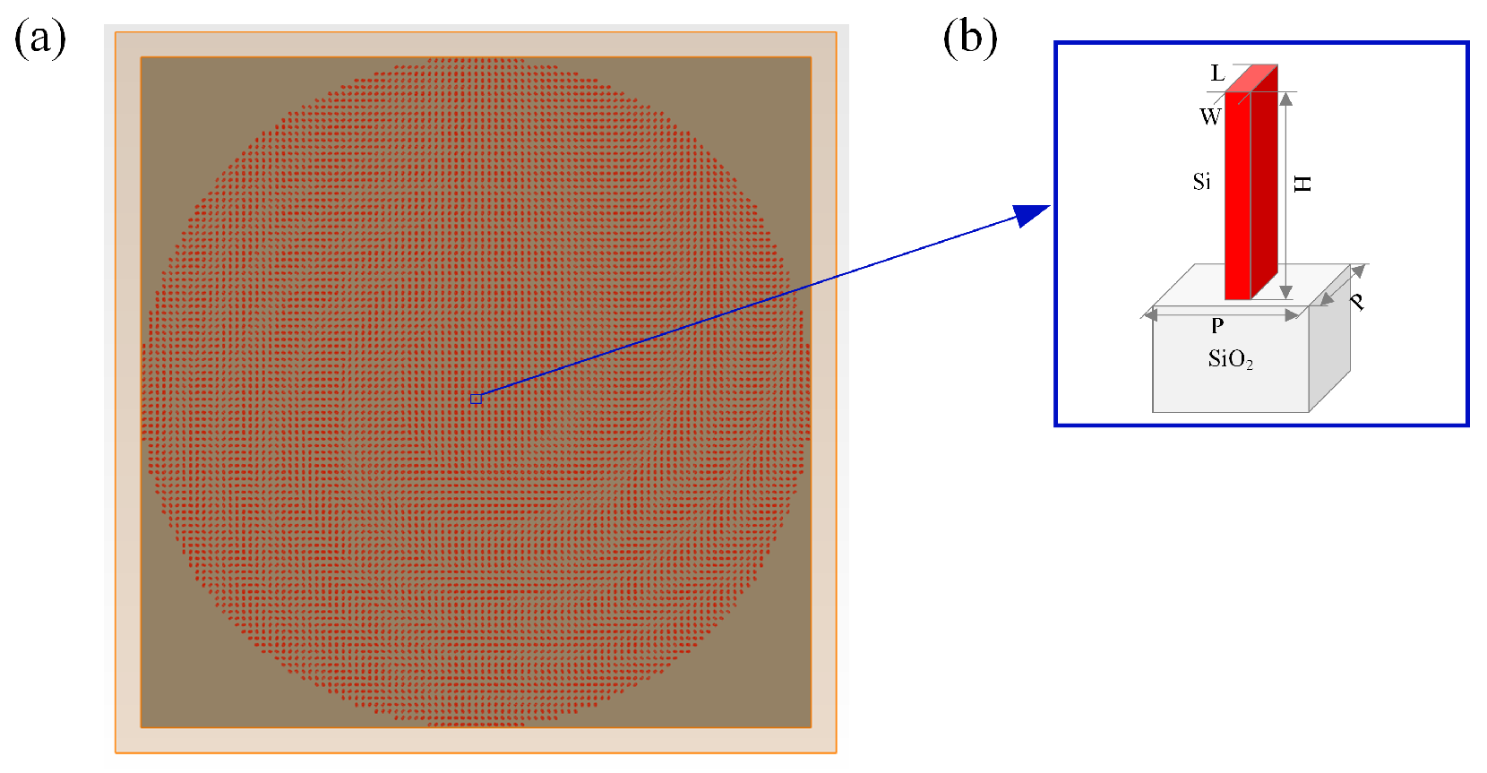
Figure 1. Nano-unit design. (a) Schematic of a single Moiré metalens. (b) Schematic of the nano-unit structure, consisting of a nano-pillar (red) on a substrate (gray).
Photonics 12 00888 g001
Figure 2. Nano-unit optimization. (a) The variation in the Figure of Merit (FOM) with iteration number during the particle swarm optimization. (b) The parameter sweep of the optimized nano-unit structure, with the blue curve denoting transmittance and the red curve denoting phase.
Photonics 12 00888 g002
Figure 3. Fresnel phase design. (a) Schematic of the Fresnel phase inverse design. (b) Phase distribution for a preset focal offset F o f f s e t = 30 μm.
Photonics 12 00888 g003
Figure 4. Verification of the Fresnel phase and construction of the metalens model. (a) Schematic of the metalens model. (b) Intensity distribution in the x–z plane. (c) Intensity distribution in the x–y plane. (d) Intensity profile along the x axis.
Photonics 12 00888 g004
Figure 5. Phase distributions of Moiré metalens based on the Fresnel phase model. (a) Φ 1 phase. (b) Φ 2 phase.
Photonics 12 00888 g005
Figure 6. Phase distribution of k F o f f s e t φ /3 π .
Photonics 12 00888 g006
Figure 7. Simplified phase distributions. (a) Φ 1 phase. (b) Φ 2 phase.
Photonics 12 00888 g007
Figure 8. Phase distributions of the modified Moiré varifocal metalens. (a) T 1 metalens. (b) T 2 metalens.
Photonics 12 00888 g008
Figure 9. Schematic of the Moiré metalens varifocal operation.
Photonics 12 00888 g009
Figure 10. Intensity distributions in the x–z plane for the MMVLs at sampled angles throughout one full rotation.
Photonics 12 00888 g010
Figure 11. Intensity distributions in the x–z plane for the TMVLs at sampled angles throughout one full rotation.
Photonics 12 00888 g011
Figure 12. Comparative varifocal performance of MMVLs and TMVLs across a full rotation cycle. (a) Normalized intensity versus rotation angle. (b) Focusing efficiency comparison.
Photonics 12 00888 g012
Figure 13. Comparison of focal lengths at various angles during one rotation cycle for MMVLs and TMVLs.
Photonics 12 00888 g013
Figure 14. FWHM evolution for MMVLs.
Photonics 12 00888 g014
Figure 15. Error analysis schematic. (a) Axial distance. (b) Off-center.
Photonics 12 00888 g015
Figure 16. Field distributions in the x–z and x–y planes for the MMVLs (top row) and TMVLs (bottom row) as the axial distance increases from 0 to 20 d 0 .
Photonics 12 00888 g016
Figure 17. Performance comparison of MMVLs and TMVLs across axial distance from 0 to 20 d 0 . (a) Normalized intensity curves. (b) Focusing efficiency curves.
Photonics 12 00888 g017
Figure 18. The FWHM variation of the MMVLs.
Photonics 12 00888 g018
Figure 19. Field distributions in the x–z and x–y planes for the MMVLs (top row) and TMVLs (bottom row) across off-center from 0 to 10 p 0 .
Photonics 12 00888 g019
Figure 20. Performance comparison of MMVLs and TMVLs across off-center from 0 to 10 p 0 . (a) Normalized intensity curves. (b) Focusing efficiency curves.
Photonics 12 00888 g020
Figure 21. The FWHM variation of the MMVLs.
Photonics 12 00888 g021
Disclaimer/Publisher’s Note: The statements, opinions and data contained in all publications are solely those of the individual author(s) and contributor(s) and not of MDPI and/or the editor(s). MDPI and/or the editor(s) disclaim responsibility for any injury to people or property resulting from any ideas, methods, instructions or products referred to in the content.