Article

Designing an SOI Interleaver Using Genetic Algorithm

1
Engineering Physics and Mathematics Department, Faculty of Engineering, Ain Shams University, Cairo 11517, Egypt
2
Electronics and Communications Department, Faculty of Engineering, Arab Academy for Science and Technology and Maritime Transport, Cairo 2033, Egypt
3
Center of Excellence in Nanotechnology, Arab Academy for Science and Technology and Maritime Transport, Cairo 2033, Egypt
4
Department of Computer Sciences, Faculty of Sciences, Lebanese University, Fanar 2611, Lebanon
5
Computer and Systems Engineering Department, Faculty of Engineering, Ain Shams University, Cairo 11517, Egypt
6
Electrical Engineering Department, Future University in Egypt, Cairo 11835, Egypt
7
Department of Electronics and Communications Engineering, Faculty of Engineering, Ain Shams University, Cairo 11517, Egypt
*
Authors to whom correspondence should be addressed.
Photonics 2025, 12(8), 775; https://doi.org/10.3390/photonics12080775 (registering DOI)
Submission received: 26 April 2025 / Revised: 23 July 2025 / Accepted: 28 July 2025 / Published: 31 July 2025
(This article belongs to the Special Issue Advanced Materials and Devices for Silicon Photonics)

Abstract

A multi-objective genetic algorithm is tailored to optimize the design of a wavelength interleaver/deinterleaver device. An interleaver combines data streams from two physical channels into one. The deinterleaver does the opposite job. The WDM requirements for this device include channel spacing of 50 GHz, channel bandwidth of 20 GHz, free spectral range of 100 GHz, maximum channel dispersion of 30 ps/nm, and maximum crosstalk of −23 dB. The challenges for the optimization process include the lack of a closed-form expression for the device performance and the trade-off between the conflicting performance parameters. So, for this multi-objective problem, the proposed approach maneuvers to find a compromise between the performance parameters within a few minutes, saving the designer the laborious design process previously proposed in the literature, which relies on visually inspecting the Z-plane for the dynamics of the transmission poles and zeros. Designs of better performance are achieved, with fewer ring resonators, a channel dispersion as low as 1.6 ps/nm, and crosstalk as low as −30 dB.

1. Introduction

Integrated optics continue to progress in various directions. One focus is the quest of new materials with tailored optical properties [1,2]. Another involves circuit design, including, for example, electro-optic modulators [3,4,5,6,7], filters [8], mid-infrared structures [9,10,11], gyroscopes [12,13], switches, grating couplers, optical crossing structures [14], spot size converters [15,16], vertical coupling [17], edge coupling [18,19], reflectors [20], polarization splitters [21,22], polarization rotators [23,24,25], logic gates [26], sensors [27,28,29,30,31,32,33], and light detection and ranging (LiDAR) devices [34]. The third direction includes design techniques that have evolved from simple calculations [35] and modeling to numerical simulations [36], optimization techniques, and machine learning [37,38,39,40,41]. One particularly intriguing device that has garnered significant attention is the wavelength interleaver/deinterleaver circuit [42]. The interleaver combines two different data streams to travel along one physical channel. The deinterleaver circuit separates two data streams from one into two physical channels. Typically, a single structure can switch from one function to another by reversing the data flow direction. The design must adhere to wavelength division multiplexing (WDM) requirements. These latter include channel spacing of 50   G H z , free spectral range ( F S R ) for one channel of 100   G H z , channel 3 dB bandwidth of at least 20   G H z , maximum channel crosstalk of 23     d B , and finally maximum channel dispersion of 30   p s / n m [42].
An interesting design approach was presented in [42]. In this approach, the design revolves around studying circuit transmission in the Z-domain. Single-mode waveguides are employed. The ring circumference, R , is defined through the relation F S R = c 2 π R N g = 100   G H z , where N g = 4 is the group refractive index, which is dictated by the technology of fabrication [43]. The design parameters are then the coupling coefficients for the circuit components, ring resonators, and buses. Then, adjusting the coupling coefficients manipulates the transmission poles and zeros until they are placed as closely as possible to the desired locations on the Z-plane. However, despite being an insightful approach, it is tedious and time-consuming to rely on the visual inspection of the dynamics of the poles and zeros. Furthermore, this complex approach makes it challenging for the designer to inspect other designs with different structures or numbers of rings.
In this work, an alternative design approach based on the genetic algorithm (GA) [38,39,40,44,45,46,47,48,49,50,51] using MATLAB 2024a is introduced along with a competitive final design for the interleaver/deinterleaver. Using the GA in silicon photonics design continues to prove very attractive and useful in the literature [47,52,53,54]. However, applying the GA to this specific problem is not straightforward. The classical GA approach requires careful modification to overcome two main core challenges in this design. The primary challenge lies in striking a balance between various conflicting performance parameters to find the best design. For instance, increasing the bandwidth results in more overlap between the channel transmission spectra, and hence worse crosstalk, and vice versa. In other words, optimizing one parameter for the best possible performance may lead to the deterioration of another performance parameter. Therefore, pursuing the best value for each parameter individually is a pitfall for such a problem. The other challenge is that there is no closed-form analytical expression that relates the output to the input in this photonic circuit. The calculations are based on matrix multiplication and numerical analysis. In short, this is a multi-objective optimization problem with no characteristic equations. Therefore, in this work the classical GA approach is specifically tailored to handle the complex design. The approach proposed here favors the smallest, and not the largest, acceptable value for each parameter to the parent of the next generation. As the calculations progress from one generation to the next, the new generation becomes closer to finding a ‘middle ground’ for all of the device performance parameters and, consequently, catching a viable solution where all, not some, of the conditions are met. The result of this approach is a circuit design with five ring resonators instead of seven, as in [42], yet maintaining a competitive performance. The proposed GA approach saves time and effort, as it catches the best design within minutes for a regular laptop with 12   G B of RAM and an Intel(R) Core(TM) i5-8250U CPU @1.60 GHz processor. There is no need to visually inspect the Z-plane for the dynamics of poles and zeros.
The structure of this work is outlined as follows. In Section 2, the circuit structure in [42] is quickly reviewed. Section 3 delves into the new genetic algorithm (GA) approach, offering a comprehensive presentation of its methodology. In Section 4, the new design of the interleaver/deinterleaver circuit is discussed before concluding in Section 5.

2. An Overview of the Interleaver Circuit

The device configuration of interest [42] is shown in Figure 1. This device has two stages. The rings in the entire structure are identical, with the same radius R . The first section, to the left of the figure, is known as the parallel-cascaded micro-ring array [55] and as “side-coupled integrated spaced sequence of resonators”, or SCISSORs [56]. The number of rings in this section is given by N s . Here, the rings are not mutually coupled but instead each ring is coupled to two bus waveguides. The distance from the center of one ring to the next is the same and is designated by L b . Typically, L b is set to L b = π R to attain Bragg reflection peaks [56]. In the second section, the rings are coupled to one another and are sandwiched between two bus waveguides. This section appears to the right in Figure 1 and is known as coupled-resonator optical waveguides, or CROWs [57], and its number of rings is given by N c .
As shown in Figure 1, mixed data streams, given by the input electric field E i n , enter at the input port to split into two distinct channels, referred to as the through and the drop ports with the fields E r and E d , respectively. This configuration represents the device operating in the deinterleaving mode. The interleaver action takes place by reversing the data flow direction. The through field of the SCISSOR section, E r s , serves as the input to the CROW section. The drop field at the CROW upper bus, E d c , is irrelevant in the context of this work. Also, it is worth noting that there is no electric field at the ports with no arrows in Figure 1, i.e., the right port of the SCISSOR top bus and the left port of the CROW upper bus.
Such structures are generally analyzed using the matrix formalism. For the SCISSOR section of N s rings, while neglecting the CROW section in Figure 1, the formulation goes as follows [55]. There are only three electric field components to consider: the input electric field, E i n , the lower bus through the electric field before the CROW section, E r s , and the upper-bus output or drop electric field, E d . As previously mentioned, there is no electric field at the upper right port of the SCISSOR section. The field E r s is then the input to the CROW section. The scattering matrix, M s , representing the relation between the SCISSOR fields, is given by:
E i n E d = M s E r s 0 ,
where:
M s = n = 1 N s 1 T s P s n × T s N s ,
T s n = 1 r l n r u n e i δ   1 r l n r u n e i δ   k l n k u n e i δ 2   k l n k u n e i δ 2   r l n r u n e i δ   ,
P s n = e i δ b   0 0 e i δ b   .
In this context, n corresponds to the ring order in the SCISSOR section, with n = 1 for the leftmost ring (closest to the input field), while k l n and r l n represent the field cross and transmission coupling coefficients between ring n and the lower bus waveguide, respectively. Similarly, k u n and r u n are the cross and transmission coupling coefficients between ring n and the upper bus, respectively. These coefficients are related to one another through r l n , u n = 1 k l n , u n 2   . The values for the coupling coefficients are determined for each ring according to the coupling apodization discussed below. The field propagation loss and phase are accounted for using δ = ( 2 π n e λ o i α 2 ) L for one trip of the field around the ring and δ b = ( 2 π n e λ o i α 2 ) L b   for the field propagation from one ring to the next through the bus. Here, λ o is the free-space wavelength, n e is the effective refractive index of the propagation mode, α is the power loss coefficient, and L is the ring circumference. As mentioned above, L b = π R = L 2 , which means that δ b = δ 2 . Note that since L and L b are constant values for the whole structure, the matrix P s is the same for any ring n .
Then, for the SCISSOR section, the through field transmission coefficient, ρ s , is given by:
ρ s = E r s E i n = 1 M s 11   .
And the drop field transmission coefficient, τ , is given by:
τ = E d E i n = M s 21 M s 11   .
Note that since the CROW section does not contribute to the drop transmission, τ is calculated solely based on the SCISSOR design.
Regarding the CROW section, the formulation proceeds as follows [55,58,59]. The input to the CROW section is the through field from the SCISSOR section, E r s . There are two output fields. The field of interest is the through field, E r . The other field at the CROW upper bus is the CROW drop field, E d c , which is irrelevant in this work. As mentioned above, there is no field present at the left port of the top bus of the CROW section. The CROW section scattering matrix is given by:
E r s E r = M c 0 E d c ,
where:
M c = n = 1 N c Q P c n × Q N c + 1 ,
Q n = 1 i k n r n 1 1 r n ,
P c = 0 e i δ   2   e i δ 2   0 .
Here, the symbols bear the same definitions from the SCISSOR description. The ring order is denoted as n , with n = 1 representing the lowermost ring. The values of the coupling coefficients are determined according to the coupling apodization discussed below. Then, for the CROW section, the through field transmission coefficient, ρ c , is given by:
ρ c = E r E r s = M c 22 M c 12   .
And the drop field transmission coefficient, τ c , is given by:
τ c = E d c E r s = 1 M c 12   .
For the whole structure, the drop transmission is found from Equation (6), while the through transmission coefficient, ρ , is then:
ρ = ρ s × e i δ b   ρ c   .
The factor e i δ b accounts for the propagation from the SCISSOR to the CROW and, for simplicity, we assume a distance L b between them.
The through and drop field transmission coefficients can be put, respectively, in the following forms:
ρ = ρ e j Φ ,
τ = τ e j Ψ .
Here, Φ and Ψ represent the phase shift for the output field at the through and drop ports, respectively, w.r.t the input field.
Consequently, the device through and drop power transmission coefficients are expressed as follows, respectively:
R = ρ 2 ,
T = τ 2 .
At this point, we define the round-trip phase shift around a ring resonator, also known as the normalized frequency, ϕ = ω F S R . Here, ω = 2 π f = 2 π c λ is the signal angular frequency and f is the signal frequency. This means that a change of ϕ of 2 π corresponds to one free spectral range, in this design 100   G H z . From [60], the dispersion of the signal is given by D = d G d λ , where G is the group delay and is given by G = d χ d ω . Here, χ is the phase delay, which is Φ for the through port and Ψ for the drop port. This leads to the relation D = d 2 χ d ω 2 . d ω d λ . But d ω d λ = 2 π c λ 2 and d 2 χ d ω 2 = 1 F S R 2 d 2 χ d ϕ 2 , which eventually gives D = 2 π c λ 2 F S R 2 d 2 χ d ϕ 2 .   So, the expressions for the signal dispersion for the through and drop ports are given by D r and D d , respectively, as follows:
D r = 2 π c λ 2 F S R 2 d 2 Φ d ϕ 2 ,
D d = 2 π c λ 2 F S R 2 d 2 Ψ d ϕ 2 .
More design rules include maintaining equal ring–bus coupling coefficients on both sides of each ring in the SCISSOR section, in order to evade undesirable notches in the passband [61]. Specifically, it means that k l = k u in the formula mentioned earlier. Moreover, the coupling coefficients need not be uniform across the entire structure. Coupling spatial apodization is usually needed to attain low crosstalk [61] and steeper side walls for the main passband [56]. One common apodization function is Gaussian apodization [62], which is adopted in this work. For the SCISSOR section, the apodization formula is:
k n = A s e B s n N s 2 0.5 2 ,
where k n is the ring–bus field coupling coefficient, A s is the coupling prefactor, B s is the apodization coefficient, and n = 1 , 2 , . . ,   N S . On the other hand, for the CROW section, the formula is:
k n = A c e B c n N c 2 1 2 .
In the CROW section, the symbols A c and B c bear the same definition as A s and B s , respectively. Recall that in the CROW section, only two rings are coupled to the bus waveguides. Therefore, the given formula with n = 1 , 2 , . . , N c + 1 ensures the spatial symmetry of the coupling coefficients. Note that the ring–bus coupling is given by k 1 at the bottom of the CROW and k N c + 1   at the top, with k 1 = k N c + 1 .

3. The Compromised Optimization Approach

As previously discussed, optimizing the device performance entails determining the coupling coefficients for each pair of coupled elements to satisfy the interleaver/deinterleaver WDM requirements. This challenge characterizes the problem as multi-objective, with conflicting performance parameters and no closed-form mathematical expression for the transmission. The approach introduced in this work addresses this issue by selecting the minimum acceptable values for each parameter to propagate through the generations instead of the maximum possible values. This concept is elucidated through the following formulation.
The primary focus lies on six key performance parameters, namely, the bandwidth ( B W r and B W d ), the crosstalk ( C T r   a n d   C T d ), and the dispersion ( D r   a n d   D d ) for the through and the drop channels, respectively. For each, a ‘performance metric’ is established, representing the difference between the value of the performance parameter and the value set by the WDM conditions. This metric is computed such that if the metric value is zero, then the performance parameter precisely fulfills the requirement. If the performance metric is positive, it indicates that the performance parameter exceeded the requirement. Conversely, a negative metric suggests that the performance parameter falls short of the specified requirement. Therefore, for the above performance parameters, listed in the same order, the following performance metrics are defined:
M B W r = B W r 20 ,
M B W d = B W d 20 ,
M C T r = 23 C T r ,
M C T d = 23 C T d ,
M D r = 30 D r ,
M D d = 30 D d ,
with the units G H z for the bandwidth, d B for the crosstalk, and   p s n m for the dispersion. As an illustration, if M D d = 3   p s n m , then the dispersion of the drop port D d = 27   p s n m , which is 3   p s n m better than the allowed maximum of 30   p s n m .
The design parameters, serving as inputs to the algorithm, are A s , B s , A c , and B c , which determine the coupling coefficients. The values of A s and A c cannot be zero or less, while B s and B c can take any value, whether positive or negative, but not zero. Of course, the values of the design parameters are rigorously examined to ensure that the coupling coefficient does not exceed 100%, which is the physical limit. If such a scenario arises, the selected values for the design parameters are omitted and other values are attempted.
In line with the approach described in [42], losses are assumed to be 10 % per one complete trip around the ring. The number of rings for each section, SCISSOR and CROW, is predetermined by the designer and remains constant throughout the optimization process.
In the first step, the genetic algorithm components are prepared as follows. A generation is given by a matrix. In this matrix, each row represents a chromosome. The number of chromosomes is n c and can be chosen according to the trade-off between the processing time, which decreases as n c decreases, and the probability of hitting a solution or more, which increases as n c increases. In other words, if n c increases, then the probability to hit a solution increases at the expense of the processing time. Each chromosome consists of genes, which are the columns in the generation matrix. There are four genes in this problem, which are the four design parameters A s , B s , A c , and B c . These genes are encoded in the binary format. So, the generation matrix has the size n c × 4 . Only for the first generation in the process are random numbers assumed for the four design parameters. The random numbers must be checked before being employed, such that the values of A s , B s , A c , and B c do not give coupling coefficients above 100 % . The number of generations, n g , is chosen by the designer in the same way the number of chromosomes per generation, n c , is chosen. It is a trade-off between the processing time and the probability of hitting a solution of more. In this work, we found n g = 100 is good enough to ensure finding a proper solution in a few minutes. After the first generation is done, the jump to the next generation is determined according to the selection criteria explained below.
Second, each chromosome is employed to calculate the through and drop transmission of the interleaver. The performance parameters are calculated, and hence the performance metrics for each chromosome.
In the third step, for each chromosome, the performance metrics are classified into two groups. Group A includes the metrics with values greater than or equal to zero. These metrics correspond to the performance parameters that met or exceeded the WDM requirements. In contrast, Group B includes the negative metrics, which correspond to the performance parameters that fell short of the requirements. An optimal chromosome, or a “good” design, is characterized by having an empty Group B. In other words, it indicates that all of its performance parameters have successfully met or exceeded the WDM requirements.
The optimization process relies on calculating two crucial values, denoted as “a” and “b”, which play a pivotal role in the ‘middle ground’ approach:
  • “a” represents the average of the values in Group A, which contains metrics corresponding to performance parameters that have either met or exceeded the wavelength division multiplexing (WDM) basic targets. A higher “a” value for a chromosome indicates that its performance parameters are further beyond the WDM requirements.
  • “b” represents the average of the values in Group B, consisting of negative metrics corresponding to performance parameters falling short of the requirements. Since “b” is negative, larger values imply values closer to zero. Therefore, a higher “b” value suggests that some performance parameters performed poorly.
The challenge is to select which chromosomes will parent the next generation. In this context, a good chromosome is one with low a values and/or large b values. Note that b is negative and hence ‘larger values’ means values closer to zero. Half of the current generation is used to parent the next. Then, a quarter of the generation is selected where the chromosomes have the smallest a values and another quarter with the largest b values. These two quarters are allowed to mate to generate the next generation during the crossover step.
The value of b serves as the ‘cost function’ for the process and can be employed as a guiding metric to monitor the evolution of the optimization process. Again, a chromosome with b = 0 represents an acceptable design since for this chromosome, i.e., this set of coupling coefficients, no performance parameter is below the corresponding WDM requirement.
In the fourth step, an additional tool, mutation, is utilized. Mutation is needed for two reasons. In case the search process hits a solution, mutation is applied to intentionally perturb the solution, forcing the search process away from the current solution in the hope of discovering another viable solution that may better meet the optimization goals. Also, if the process saturates away from a solution, mutation provides a means to inject randomness and encourage the process to explore alternative regions of the solution space.
Upon completing these four steps, the process starts over with the next generation. Instead of starting with a random guess of coupling coefficients, as done for the first generation, the subsequent generations are created through the crossover and mutation processes, as in steps 3 and 4. This iterative process continues until a predefined stopping criterion is met. The stopping criterion in this work is defined as completing n g = 100 generations of calculations.

4. Optimization Results

In the design proposed in this work, the number of rings used is five, with three rings in the SCISSOR section and two in the CROW section. This configuration aligns with the design reported in [63], which is two rings less than the design presented in [42]. A comparison of these designs is detailed in Table 1.
The assumption in [42,63] that 10 % of light power is dissipated per one ring resonator cycle is adopted in this work too. Also, the power loss due to light propagation through the straight waveguide linking the SCISSOR section to the CROW section is not stated clearly in [42]. In this work, we assume this link to be L b or π R long, which means power loss of approximately 0.2   d B . Therefore, to ensure a fair comparison, the insertion loss for the through port in [42] is adjusted by increasing it by 0.2   d B . Apodization is not used in [63], but instead all ring–ring coupling coefficients are assumed to be equal [64]. Also, the ring–bus coupling is equal for both bus waveguides in the first section, which is different from that in the second section in [63]. The bandwidth values for the final design in [42] are extracted from the graphs, as they are not explicitly mentioned. Finally, the coupling coefficients in [42] are power coupling coefficients instead of field coupling coefficients, as followed in the current work. For the SCISSOR section in [42], the apodization prefactor is 0.5 and the apodization factor is 0.176 . For the CROW section, the power coupling coefficient between the bus and the ring is 0.8 , and that between a ring and the next is 0.39 . Taking the square root of these values and assuming Gaussian apodization, as in the current work, the prefactor and the coupling coefficient are calculated and documented in Table 1.
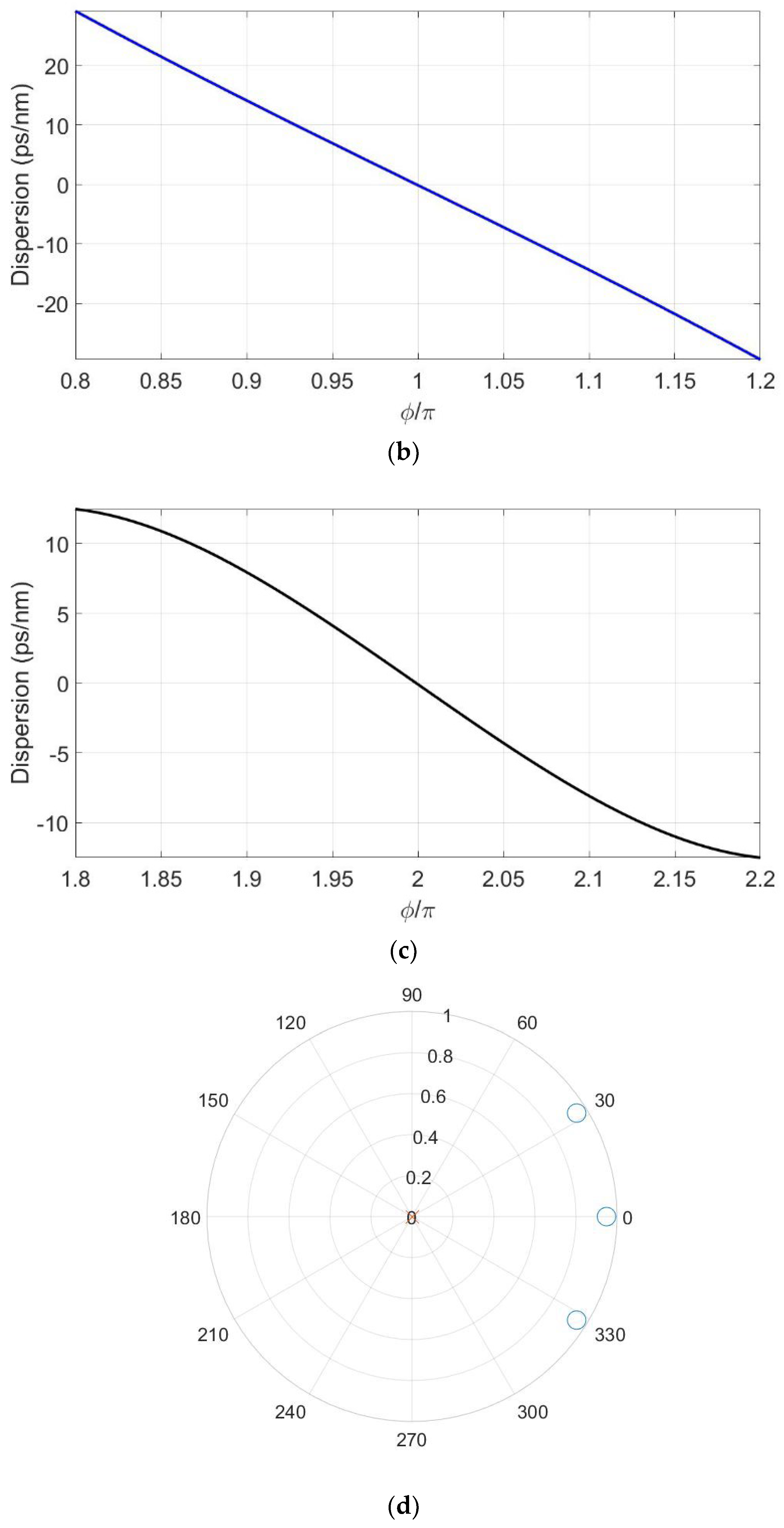
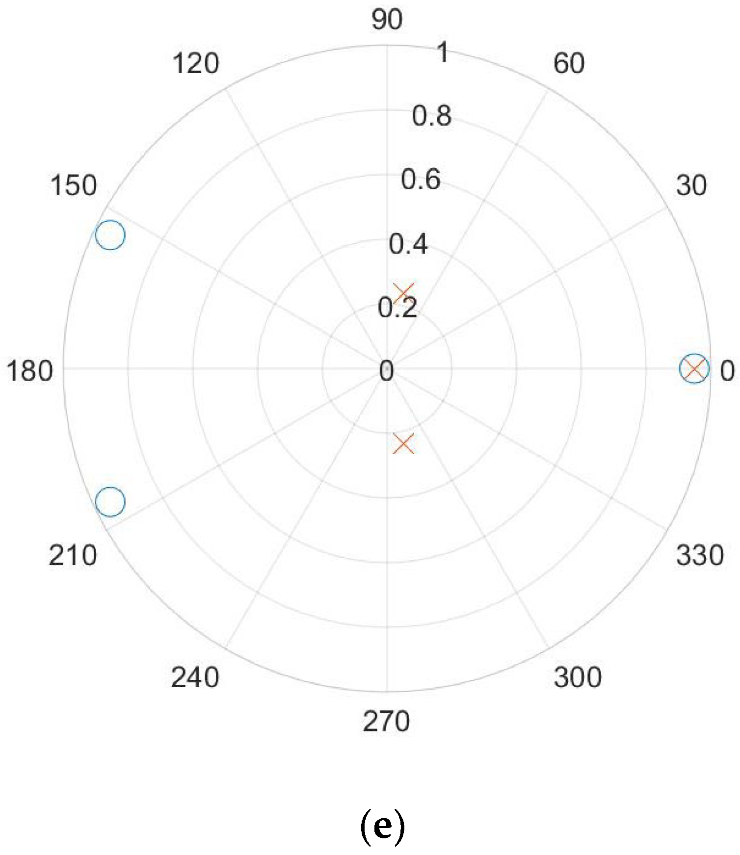
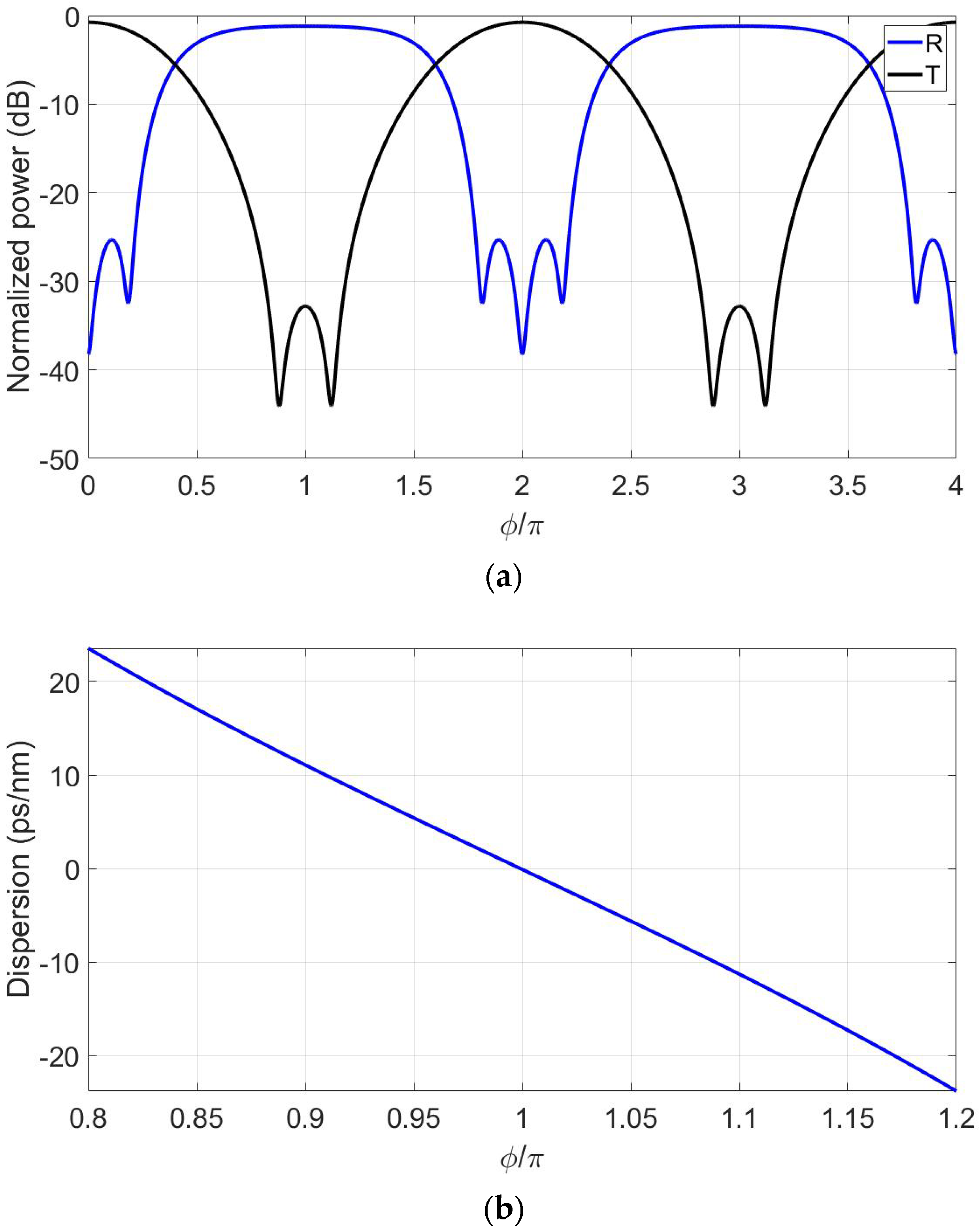
The values in Table 1 show that the two proposed designs exceed the WDM requirements for the interleaver/deinterleaver device. Note that the reported values for the dispersion and crosstalk are the highest within the ± 10   G H z bandwidth boundaries. Therefore, it is not very advantageous for the bandwidth to go beyond the WDM minimum of 20   G H z since the very high crosstalk and dispersion will cause too much distortion to the data. Compared to the design in [63], which has the same number of ring resonators of five, the proposed design 1 shows better crosstalk and drop signal dispersion. Design 2 also shows better crosstalk and a significant low dispersion at the drop port of 1.6   p s n m . Compared to the design in [42], which has seven rings, the dispersion of the proposed designs is very low for the drop port and comparable for the through port. It is natural, though, for seven rings to do better in terms of the crosstalk because the bandwidth can be much limited with extra zeros available to the filter system. However, with five rings, higher fabrication density on-chip can be achieved. More importantly, considering the sensitivity of the device performance to the values of the coupling coefficients, the effect of fabrication tolerance is expected to have a much smaller effect on the practical results for a design with five rings when compared with a design with seven rings. The power transmission, dispersion, and pole-zero diagrams are shown in Figure 2 and Figure 3 for designs 1 and 2, respectively.
Equally important are the advantages provided using the proposed optimization technique. This technique provides quick access to multiple designs with diverse advantages. The designer can quickly catch a design with very low dispersion or another with very low crosstalk, as discussed above. On the other hand, the design approach in [42] utilizes the Z-transform in order for the designer to study the dynamics of the poles and zeros of the device’s two transmission ports as the coupling coefficients are varied. The visual inspection is then necessary to achieve the target positions of the poles and zeros before checking the corresponding transmission power diagrams. This tedious and very slow process should be re-carried out for a device with different features.
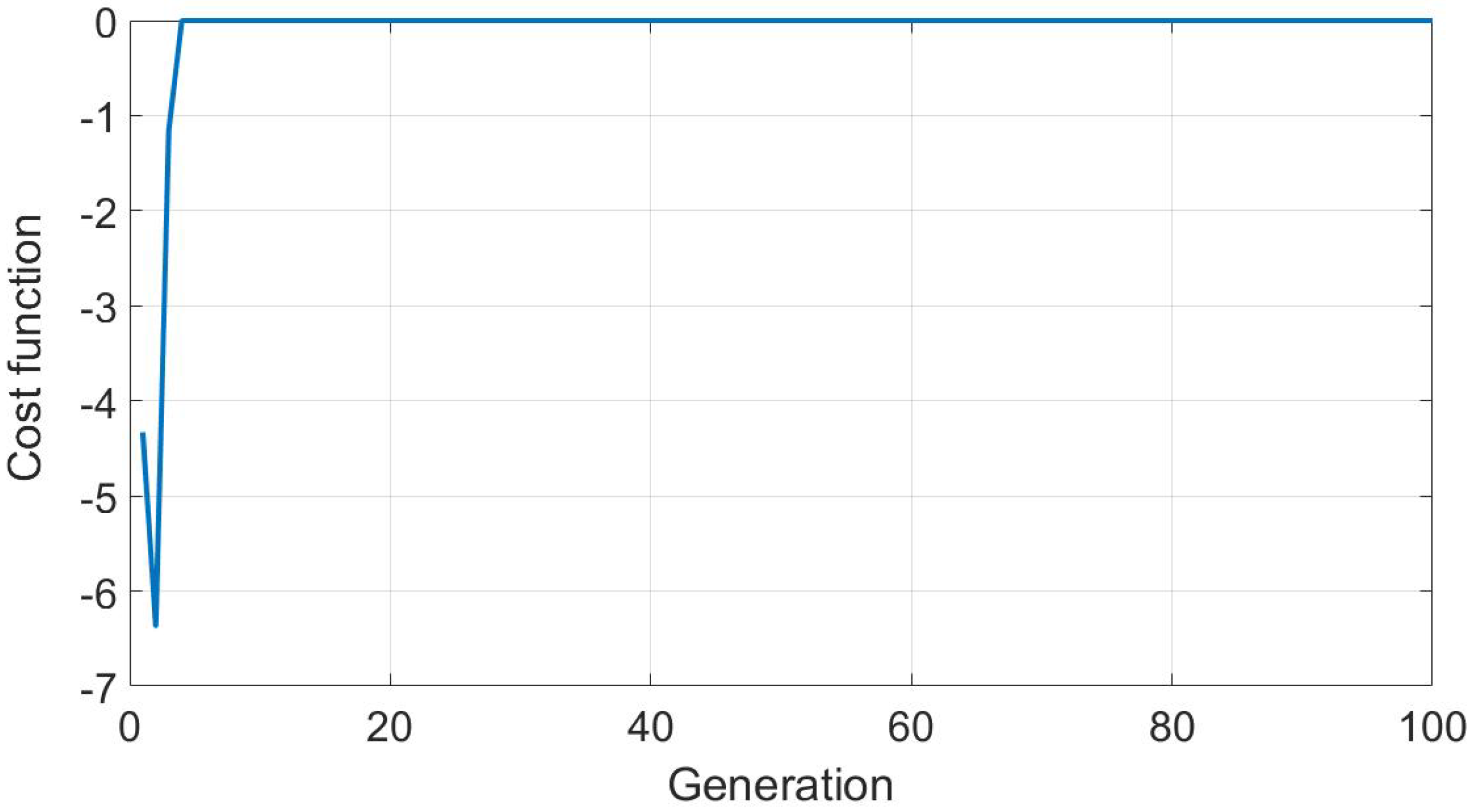
As explained above, the optimization algorithm has a cost function, b , that represents the average of the negative performance metrics. A solution is valid when the corresponding b equals zero, which means that all performance metrics met their targets. The number of generations in these calculations is n g = 100 generations, and the number of chromosomes per generation is n c = 100 chromosomes. Each chromosome represents one set of coupling coefficients. The stopping criterion is when all generations are attempted. In Figure 4, the evolution of b is drawn versus the generation number. In this figure, for each generation, the corresponding b is the best amongst all chromosomes in this generation. Clearly, within a few generations, b = 0 is achieved. The time taken from the beginning of the calculations until finding the first acceptable solution depends on how good the initial guess is, i.e., the coupling coefficient values chosen randomly for the first generation. Typically, it takes about half a minute to do the calculations for 1 generation with 100 chromosomes using an i5 laptop with a 1.6 GHz processor and 12 GB of RAM, and the first solution is found within 10 generations, i.e., 5 min.

5. Conclusions

In this work, a customized genetic algorithm was proposed to optimize the design of a wavelength interleaver device. The algorithm handles a multi-objective problem that has no closed-form expression with contradicting objectives. Targeting the best possible value for each objective, or performance parameter, results in deterioration of another parameter. Therefore, the proposed approach for the genetic algorithm navigates away from extremely outperforming parameters and, instead, targets the middle ground, where all parameters satisfy the WDM requirements even if some can do much better. The result is two new designs with competitive performance in terms of dispersion, crosstalk, fabrication density, and fabrication tolerance. The proposed approach saves the designer the tedious design, formerly followed by other works, where the poles and zeros of the interleaver transmission are optimized visually. Such an approach consumes time and does not facilitate catching various circuit designs. It can also be used to handle similar design problems, such as electro-optic modulators.

Author Contributions

Conceptualization, M.G., M.F., M.A., H.M., A.S., M.I. and W.F.; formal analysis, M.G., M.F., M.A., H.M., M.M.S. and A.S.; funding acquisition, M.F., G.A.E. and M.M.S.; investigation, M.F., M.A., H.M., G.A.E., M.M.S., A.S., M.I. and W.F.; methodology, G.A.E., A.S., M.I. and W.F.; software, M.G., H.M. and G.A.E.; supervision, A.S. and W.F.; validation, M.G., M.F., M.A., H.M., M.M.S., M.I. and A.S.; visualization, M.G. and M.A.; writing—original draft, M.G. and M.A.; writing—review and editing, M.G., M.F., H.M., G.A.E., M.M.S., A.S., M.I. and W.F. All authors have read and agreed to the published version of the manuscript.

Funding

This research received no external funding.

Institutional Review Board Statement

Not applicable.

Informed Consent Statement

Not applicable.

Data Availability Statement

Data will be provided upon reasonable request from the corresponding author.

Conflicts of Interest

The authors declare no conflict of interest.

References

  1. Monir, M.; El-Refaei, H.; Khalil, D.; Omar, O. Assessment of the NM-lines sensitivity for measurement errors. Fiber Integr. Opt. 2007, 26, 1–15. [Google Scholar] [CrossRef]
  2. Monir, M.; El-Refaei, H.; Khalil, D. Single-mode refractive index reconstruction using an NM-line technique. Fiber Integr. Opt. 2006, 25, 69–74. [Google Scholar] [CrossRef]
  3. Mahrous, H.; Fedawy, M.; El Sabbagh, M.; Fikry, W.; Gad, M. 130 Gbps low-loss electro-optic modulator based on metal-oxide-semiconductor technology. Optik 2020, 217, 164928. [Google Scholar] [CrossRef]
  4. Mahrous, H.; Fedawy, M.; El Sabbagh, M.; Fikry, W.; Gad, M. A compact 120 GHz monolithic silicon-on-silica electro-optic modulator. Opt. Quantum Electron. 2020, 52, 111. [Google Scholar] [CrossRef]
  5. Mahrous, H.; Azmy, M.; Afifi, A.; Abouelainain, A.; Kotb, A.; Fedawy, M.; Fikry, W.; Gad, M.; Selim, D. Design of compact, high-speed and low-loss silicon-on-silica electro-optic modulators. Semicond. Sci. Technol. 2020, 35, 095017. [Google Scholar] [CrossRef]
  6. Mahrous, H.; Gad, M.; El Sabbagh, M.; Fedawy, M.; Fikry, W. A High-Speed Electro-Optic Modulator with Optimized Electrode Positions. In Proceedings of the 2018 13th International Conference on Computer Engineering and Systems, ICCES 2018, Cairo, Egypt, 18–19 December 2018; pp. 530–535. [Google Scholar] [CrossRef]
  7. Rahim, A.; Hermans, A.; Wohlfeil, B.; Petousi, D.; Kuyken, B.; Van Thourhout, D.; Baets, R. Taking silicon photonics modulators to a higher performance level: State-of-the-art and a review of new technologies. Adv. Photonics 2021, 3, 024003. [Google Scholar] [CrossRef]
  8. Shalaby, R.A.; Adib, G.; Sabry, Y.M.; Gad, M.; Khalil, D.; Sabry, Y.M.; Khalil, D. Silicon photonic coupled-ring resonator in nested configuration comprising different length scales. In Proceedings of the 2019 14th International Conference on Computer Engineering and Systems (ICCES), Cairo, Egypt, 17 December 2019; Institute of Electrical and Electronics Engineers (IEEE): Piscataway, NJ, USA, 2020; pp. 432–437. [Google Scholar] [CrossRef]
  9. Labib, M.; Gad, M.; Sabry, Y.M.; Khalil, D. Strip Waveguide Enabling Low Loss for Silicon on Silica Technology in the MIR. In Proceedings of the 2018 13th International Conference on Computer Engineering and Systems, ICCES 2018, Cairo, Egypt, 18–19 December 2018; Institute of Electrical and Electronics Engineers Inc.: Piscataway, NJ, USA, 2019; pp. 536–540. [Google Scholar] [CrossRef]
  10. Labib, M.; Gad, M.; Sabry, Y.M.; Khalil, D. Optimization of silicon on silica waveguides for mid-infrared applications at 4.28 um. Silicon Photonics XIV 2019, 10923, 155–165. [Google Scholar] [CrossRef]
  11. Labib, M.; Gad, M.; Sabry, Y.M.; Khalil, D. Extended Wavelength Silicon-on-Silica Photonics Platform: Design Case Study for Gas Sensing in the Mid-infrared Range. Silicon 2025, 17, 2089–2103. [Google Scholar] [CrossRef]
  12. Shukri, Z.; Rezaei, H.; Fasihanifard, M.; Ghofrani, S.; Bissonnette, J.; Gravey, T.; Romanuik, S.; Tewari, R.; Zandi, K. Photonic integrated circuit microchip-based optical gyroscopes for high-precision inertial measurement units. Integr. Opt. Devices Mater. Technol. XXIX 2025, 13369, 74–87. [Google Scholar] [CrossRef]
  13. Wang, L.; Sun, D.; Liu, W.; Lu, Z.; Fan, S.; Liu, H.; Jin, L.; Feng, J.; Xu, W.; Jiao, H.; et al. Analysis and suppression of passive chip stray light for integrated optical gyroscopes. Opt. Commun. 2025, 577, 131454. [Google Scholar] [CrossRef]
  14. Griol, A.; Håkansson, A.; Brimont, A.; Cuesta, F.; Martí, J.; Galán, J.V.; Sanchis, P.; Villalba, P. Highly efficient crossing structure for silicon-on-insulator waveguides. Opt. Lett. 2009, 34, 2760–2762. [Google Scholar] [CrossRef]
  15. Shoji, T.; Tsuchizawa, T.; Watanabe, T.; Yamada, K.; Morita, H. Spot-size converter for low-loss coupling between 0.3-μm-square Si wire waveguides and single-mode fibers. In Proceedings of the 15th Annual Meeting of the IEEE Lasers and Electro-Optics Society, Glasgow, UK, 10–14 November 2002; IEEE: Piscataway, NJ, USA, 2003; pp. 289–290. [Google Scholar] [CrossRef]
  16. Sánchez-Sánchez, A.; Pérez-Armenta, C.; Luque-González, J.M.; Ortega-Moñux, A.; Wangüemert-Pérez, J.G.; Molina-Fernández, Í.; Halir, R. Ultra-compact broadband spot size converter using metamaterial cell-based inverse design. arXiv 2025, arXiv:2501.06390. [Google Scholar]
  17. Huang, S.Y.; Barz, S. Compact inverse designed vertical coupler with bottom reflector for sub-decibel fiber-to-chip coupling on silicon on insulator platform. Sci. Rep. 2025, 15, 2925. [Google Scholar] [CrossRef] [PubMed]
  18. Yuan, Q.; Peczek, A.; Frankel, J.; Rishavy, D.; Mai, C.; Christenson, E.; Pratap, D.; Zimmermann, L. Fully Automated Wafer-Level Edge Coupling Measurement System for Silicon Photonics Integrated Circuits; IEEE Transactions on Semiconductor Manufacturing: Piscataway, NJ, USA, 2025. [Google Scholar] [CrossRef]
  19. Yi, X.; Zhao, W.; Zhang, L.; Dai, D. Polarization-insensitive and low-loss O-band edge coupler for silicon photonics. Opt. Lett. 2025, 50, 1699–1702. [Google Scholar] [CrossRef]
  20. Cutolo, A.; Iodice, M.; Irace, A.; Spirito, P.; Zeni, L. An electrically controlled Bragg reflector integrated in a rib silicon on insulator waveguide. Appl. Phys. Lett. 1997, 71, 199–201. [Google Scholar] [CrossRef]
  21. Fu, P.H.; Huang, T.Y.; Fan, K.W.; Huang, D.W. Optimization for ultrabroadband polarization beam splitters using a genetic algorithm. IEEE Photonics J. 2019, 11, 1–11. [Google Scholar] [CrossRef]
  22. Zafar, H.; Pereira, M.F. An efficient and compact mid-infrared polarization splitter and rotator based on a bifurcated tapered-bent waveguide. Sci. Rep. 2025, 15, 5160. [Google Scholar] [CrossRef]
  23. Dai, D.; Tang, Y.; Bowers, J.E. Mode conversion in tapered submicron silicon ridge optical waveguides. Opt. Express 2012, 20, 13425. [Google Scholar] [CrossRef]
  24. Zafar, H.; Pereira, M.F. Recent Progress in Light Polarization Control Schemes for Silicon Integrated Photonics. Laser Photonics Rev. 2024, 18, 2301025. [Google Scholar] [CrossRef]
  25. Shahwar, D.; Yoon, H.H.; Akkanen, S.-T.; Li, D.; tul Muntaha, S.; Cherchi, M.; Aalto, T.; Sun, Z. Polarization management in silicon photonics. Npj Nanophotonics 2024, 1, 35. [Google Scholar] [CrossRef]
  26. Sanchis, P.; Cuesta-Soto, F.; Blasco, J.; García, J.; Martínez, A.; Marti, J.; Riboli, F.; Pavesi, L. All-optical MZI XOR logic gate based on Si slot waveguides filled by Si-nc embedded in SiO2. In Proceedings of the IEEE International Conference on Group IV Photonics GFP, Ottawa, ON, Canada, 13–15 September 2006; pp. 81–83. [Google Scholar] [CrossRef]
  27. Ranacher, C.; Carinthian, C.C.; Hedenig, U.; Grille, T.; Lavchiev, V.; Jakoby, B. A photonic silicon waveguide gas sensor using evanescent-wave absorption. In Proceedings of the IEEE Sensors, Orlando, FL, USA, 30 October–3 November 2016; pp. 1–3. [Google Scholar] [CrossRef]
  28. Passaro, V.M.N.; Dell’Olio, F.; Casamassima, B.; De Leonardis, F. Guided-wave optical biosensors. Sensors 2007, 7, 508–536. [Google Scholar] [CrossRef]
  29. Lai, W.-C.; Chakravarty, S.; Wang, X.; Lin, C.; Chen, R.T. On-chip methane sensing by near-IR absorption signatures in a photonic crystal slot waveguide. Opt. Lett. 2011, 36, 984. [Google Scholar] [CrossRef] [PubMed]
  30. Robinson, J.T.; Chen, L.; Lipson, M. On-chip gas detection in silicon optical microcavities. Opt. InfoBase Conf. Pap. 2008, 16, 4296–4301. [Google Scholar] [CrossRef]
  31. Claes, T.; Molera, J.G.; De Vos, K.; Schacht, E.; Baets, R.; Bienstman, P. Label-free biosensing with a slot-waveguide-based ring resonator in silicon on insulator. IEEE Photonics J. 2009, 1, 197–204. [Google Scholar] [CrossRef]
  32. Baird, C.L.; Myszka, D.G. Current and emerging commercial optical biosensors. J. Mol. Recognit. 2001, 14, 261–268. [Google Scholar] [CrossRef]
  33. Ryckeboer, E.; Bockstaele, R.; Vanslembrouck, M.; Baets, R. Glucose sensing by waveguide-based absorption spectroscopy on a silicon chip. Biomed. Opt. Express 2014, 5, 1636. [Google Scholar] [CrossRef]
  34. Torres, A.; Huang, J.; Bowers, J.; Davenport, M.; Tran, M.; Pintus, P.; Komljenovic, T.; Xie, W. Heterogeneous silicon photonics sensing for autonomous cars [Invited]. Opt. Express 2019, 27, 3642–3663. [Google Scholar] [CrossRef]
  35. Okamoto, K. Fundamentals of Optical Waveguides, 2nd ed.; Elsevier: Amsterdam, The Netherlands, 2006. [Google Scholar] [CrossRef]
  36. Yevick, D.; Hermansson, B. Efficient Beam Propagation Techniques. IEEE J. Quantum Electron. 1990, 26, 109–112. [Google Scholar] [CrossRef]
  37. Aparecido de Paula, R.; Aldaya, I.; Sutili, T.; Figueiredo, R.C.; Pita, J.L.; Bustamante, Y.R.R. Design of a silicon Mach–Zehnder modulator via deep learning and evolutionary algorithms. Sci. Rep. 2023, 13, 14662. [Google Scholar] [CrossRef]
  38. Mao, S.; Cheng, L.; Zhao, C.; Khan, F.N.; Li, Q.; Fu, H.Y.; Nadeem Khan, F.; Li, Q.; Fu, H.Y. Inverse design for silicon photonics: From iterative optimization algorithms to deep neural networks. Appl. Sci. 2021, 11, 3822. [Google Scholar] [CrossRef]
  39. Chen, Z.H.; Chen, W.; Cheng, Z.; Lu, G.W.; Wang, J. Ultra-compact spot size converter based on digital metamaterials. Opt. Commun. 2022, 508, 127865. [Google Scholar] [CrossRef]
  40. Silfies, M.; Kalantarov, D.; Search, C.P. Robust highly stable multi-resonator refractive index sensor. Opt. Commun. 2018, 410, 174–179. [Google Scholar] [CrossRef]
  41. Ma, H.; Huang, J.; Zhang, K.; Yang, J. Arbitrary-direction, multichannel and ultra-compact power splitters by inverse design method. Opt. Commun. 2020, 462, 125329. [Google Scholar] [CrossRef]
  42. Kaalund, C.J.; Peng, G.D. Pole-zero diagram approach to the design of ring resonator-based filters for photonic applications. J. Light. Technol. 2004, 22, 1548–1559. [Google Scholar] [CrossRef]
  43. Gad, M.; Ackert, J.; Yevick, D.; Chrostowski, L.; Jessop, P. Ring resonator wavelength division multiplexing interleaver. J. Light. Technol. 2011, 29, 2102–2108. [Google Scholar] [CrossRef]
  44. Kumar, M.; Husain, M.; Upreti, N.; Gupta, D. Genetic Algorithm: Review and Application. SSRN Electron. J. 2020, 2, 451–454. [Google Scholar] [CrossRef]
  45. Sivanandam, S.N.; Deepa, S.N. Introduction to Genetic Algorithms; Springer: Berlin/Heidelberg, Germany, 2008; pp. 1–442. [Google Scholar] [CrossRef]
  46. Mykel, T.A.W.; Kochenderfer, J. Algorithms for Optimization; The MIT Press: Cambridge, MA, USA, 2019. [Google Scholar]
  47. Li, Z.; Zhou, Z.; Qiu, C.; Chen, Y.; Liang, B.; Wang, Y.; Liang, L.; Lei, Y.; Song, Y.; Jia, P.; et al. The Intelligent Design of Silicon Photonic Devices. Adv. Opt. Mater. 2024, 12, 2301337. [Google Scholar] [CrossRef]
  48. Crepinsek, M.; Liu, S.H.; Mernik, M. Exploration and exploitation in evolutionary algorithms. ACM Comput. Surv. (CSUR) 2013, 45, 33. [Google Scholar] [CrossRef]
  49. Hassanat, A.; Almohammadi, K.; Alkafaween, E.; Abunawas, E.; Hammouri, A.; Prasath, V.B.S. Choosing mutation and crossover ratios for genetic algorithms-a review with a new dynamic approach. Information 2019, 10, 390. [Google Scholar] [CrossRef]
  50. Abdel-Khalek, H.; Amin, F.M.; Wassel, A.R.; El-Mahalawy, A.M. Enhancement of structure and optical dispersion properties of N,N′-Bis(3-methylphenyl)-N,N′-diphenylbenzidine thin films: Impact of UV irradiation. Opt. Mater. 2021, 113, 110867. [Google Scholar] [CrossRef]
  51. Gad-Elrab, A.A.A.; El-aal, S.A.; Ghali, N.I.; Zaghrout, A.A.S. An Adaptive Context Modeling Approach Using Genetic Algorithm in IoTs Environments. Adv. Intell. Syst. Comput. AISC 2020, 1129, 184–204. [Google Scholar] [CrossRef]
  52. Zhou, X.; Yi, D.; Chan, D.W.U.; Tsang, H.K. Silicon photonics for high-speed communications and photonic signal processing. Npj Nanophotonics 2024, 1, 27. [Google Scholar] [CrossRef]
  53. Lan, Y.; Li, D.; Kai, H.; Zou, B.; Zhang, G.; Feng, S. Inverse design of ultra-compact optical logic gates by genetic algorithm. Opt. Commun. 2024, 569, 130800. [Google Scholar] [CrossRef]
  54. Fan, Z.Y.; Lin, J.M.; Zhang, T.; Dai, J.; Xu, X.Y.; Xu, K. Efficient off-chip configuration method for scalable programmable photonic integrated circuits. Commun. Phys. 2025, 8, 218. [Google Scholar] [CrossRef]
  55. Grover, R.; Van, V.; Ibrahim, T.A.; Absil, P.P.; Calhoun, L.C.; Johnson, F.G.; Hryniewicz, J.V.; Ho, P.T. Parallel-cascaded semiconductor microring resonators for high-order and wide-FSR filters. J. Light. Technol. 2002, 20, 900–905. [Google Scholar] [CrossRef]
  56. Cho, S.-Y.; Soref, R. Apodized SCISSORs for filtering and switching. Opt. Express 2008, 16, 19078. [Google Scholar] [CrossRef]
  57. Poon, J.; Scheuer, J.; Mookherjea, S.; Paloczi, G.T.; Huang, Y.; Yariv, A. Matrix analysis of microring coupled-resonator optical waveguides. Opt. Express 2004, 12, 90. [Google Scholar] [CrossRef]
  58. Celo, D.; Goodwill, D.J.; Bernier, E. Interferometric microring-resonant 2 × 2 optical switches. Opt. Express 2008, 16, 13304–13314. [Google Scholar] [CrossRef]
  59. Jeong, S.-H.; Shimura, D.; Simoyama, T.; Seki, M.; Yokoyama, N.; Ohtsuka, M.; Koshino, K.; Horikawa, T.; Tanaka, Y.; Morito, K. Low-loss, flat-topped and spectrally uniform silicon-nanowire-based 5th-order CROW fabricated by ArF-immersion lithography process on a 300-mm SOI wafer. Opt. Express 2013, 21, 30163. [Google Scholar] [CrossRef]
  60. Bruce, A.J.; Brenner, I.; Nielsen, T.N.; Gomez, L.T.; Madsen, C.K.; Lenz, G.; Cappuzzo, M.A.; Adams, L.E. An All-Pass Filter Dispersion Compensator Using Planar Waveguide Ring Resonators. In Proceedings of the Optical Fiber Communication Conference and the International Conference on Integrated Optics and Optical Fiber Communication, San Diego, CA, USA, 21–26 February 1999; p. FE6. [Google Scholar]
  61. Kaalund, C.J.; Jin, Z.; Li, W.; Peng, G.-D. Novel optical wavelength interleaver based on symmetrically parallel-coupled and apodized ring resonator arrays. Photorefractive Fiber Cryst. Devices Mater. Opt. Prop. Appl. IX 2003, 5206, 157. [Google Scholar] [CrossRef]
  62. Gómez, J.D.D. Apodized Coupled Resonator Optical Waveguides: Theory, Design and Characterization. Doctoral Dissertation, Universitat Politècnica de València, Valencia, Spain, 2013. [Google Scholar]
  63. Gad, M.; Yevick, D.; Jessop, P. Compound ring resonator circuit for integrated optics applications. J. Opt. Soc. Am. A 2009, 26, 2023. [Google Scholar] [CrossRef]
  64. Mahrous, H.; Fedawy, M.; Abboud, M.; Shaker, A.; Fikry, W.; Gad, M. A Multi-Objective Genetic Algorithm Approach for Silicon Photonics Design. Photonics 2024, 11, 80. [Google Scholar] [CrossRef]
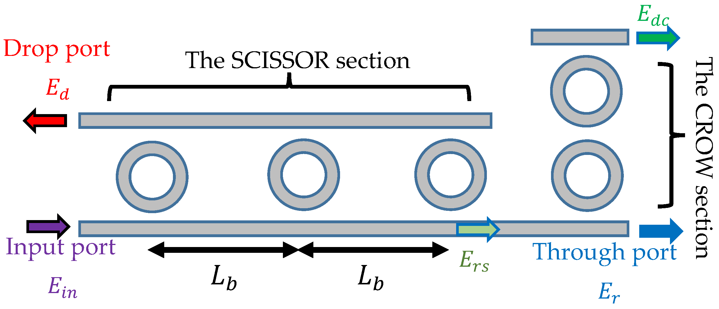
Figure 1. A schematic of the interleaver/deinterleaver circuit. The SCISSOR stage comprises three equally spaced rings to the left, while the CROW stage is composed of two rings to the right.
Photonics 12 00775 g001
Figure 2. Design 1 performance: (a) normalized power transmission, (b) through port signal dispersion, (c) drop port signal dispersion, (d) pole-zero diagram for the through port transmission, and (e) pole-zero diagram for the drop port transmission.
Photonics 12 00775 g002aPhotonics 12 00775 g002bPhotonics 12 00775 g002c
Figure 3. Design 2 performance: (a) normalized power transmission, (b) through port signal dispersion, (c) drop port signal dispersion, (d) pole-zero diagram for the through port transmission, and (e) pole-zero diagram for the drop port transmission.
Photonics 12 00775 g003aPhotonics 12 00775 g003b
Figure 4. The evolution of the cost function for the negative performance metrics, b, throughout the generations of the optimization process.
Photonics 12 00775 g004
Table 1. Comparison of interleaver designs.
Design N s N c A s B s A c B c B W r / B W d
( G H z )
C T r / C T d
( d B )
D r / D d
( p s n m )
Target
Performance
------ 20 / 20
or more
23 / 23
or less
30 / 30
or less
Work in [42]43 0.5 0.88 0.5971 0.1796 27 / 27 37 / 35 25 / 25
Work in [63] 4   a 1   a ---- 60 / 35 24 / 24 22 / 21
This work
Design 1
3 2 0.62 0.22 0.74 0.16 51 / 37 27 / 30 29 / 12
This work
Design 2
3 2 0.59 0.25 0.71 0.16 56 / 32 27 / 24 23.6/ 1.6
a The circuit in [63] has two stages, one stage with four rings and the other with one ring. However, none of these two stages is in the form of SCISSOR or CROW, unlike the work in [42] or the current work.
Disclaimer/Publisher’s Note: The statements, opinions and data contained in all publications are solely those of the individual author(s) and contributor(s) and not of MDPI and/or the editor(s). MDPI and/or the editor(s) disclaim responsibility for any injury to people or property resulting from any ideas, methods, instructions or products referred to in the content.