Article

Single-Polarization Single-Mode Hollow-Core Anti-Resonant Fiber with Low Loss and Wide Bandwidth

1
Ocean College, Jiangsu University of Science and Technology, Zhenjiang 212003, China
2
Hebei Key Laboratory of Intelligent Data Information Processing and Control, Tangshan University, Tangshan 063000, China
3
College of Artificial Intelligence, Henan University, Zhengzhou 450046, China
*
Author to whom correspondence should be addressed.
Photonics 2025, 12(7), 686; https://doi.org/10.3390/photonics12070686
Submission received: 16 June 2025 / Revised: 3 July 2025 / Accepted: 3 July 2025 / Published: 7 July 2025
(This article belongs to the Special Issue Applications and Development of Optical Fiber Sensors)

Abstract

Stable generation and propagation of single-polarization single-mode (SPSM) beams in hollow-core fiber (HCF) has become an important research direction. However, their routine use is yet to become a reality, a major obstacle is to maintain the polarization state of light at a sufficiently long transmission distance in a wide spectral range. In the paper, a hollow-core anti-resonant fiber (HC-ARF) that can support SPSM beam transmission with an average loss of 15 dB/km in wavelengths beyond 1000 nm is proposed. SPSM guidance is achieved by setting the cladding tubes in the orthogonal direction to have different structures and material properties. Different cladding tube structures break the degeneracy of polarization modes, and different cladding tube materials make the polarization modes experience enough loss difference. In the range of more than 600 nm, the y-polarization loss ≈ 9.3 dB/km, while the x-polarization is > 500 dB/km, and the birefringence is > 1.7 × 10⁻⁵. In addition, the SPSM optimization process and bending losses in different directions are also discussed in detail.

1. Introduction

Maintaining the spatial distribution and polarization state of light waves during propagation, free from external interference, is critical for applications such as high-performance interferometers, gyroscopes, and optical clocks that rely on high spatial and polarization purity for light beam transmission [1,2]. A practical solution is to leverage the flexibility and ultra-low propagation loss of fibers, which enables the development of compact sensors with lengths up to several kilometers, albeit at the cost of some degradation in optical purity [3]. However, environmental perturbations and fiber fabrication imperfections induce random birefringence, leading to unpredictable output. In solid-core fibers (SCFs), polarization control is achieved through geometric asymmetry or internal stress, which can effectively counteract environmental interference [4]. Nevertheless, material absorption, low damage thresholds, and optical nonlinearity fundamentally restrict their application to wavebands where the glass is transparent, as well as to optical powers low enough to avoid undesired nonlinear effects and/or dielectric damage [5]. A potential approach to combine spatial stability, reduced optical nonlinearity, and environmental insensitivity of free-space-based systems with the long propagation lengths and compactness of coiled fibers is to employ hollow-core fibers (HCFs). HCFs with large transmission bandwidth, low power overlap with cladding, low loss, and extremely low polarization mode coupling have become an attractive medium for various interferometric sensors, offering significant advantages in reducing noise levels and improving sensitivity [6,7].
Hollow-core anti-resonant fiber (HC-ARFs) have achieved significant progress in loss reduction, with the latest reported loss being less than 0.11 dB/km [8]—a value that even exceeds the loss limit of SCFs [9]. However, flexible and stable polarization control in HCF still faces significant challenges. Traditional methods, such as introducing mechanical stress in SCFs or breaking the core symmetry, cannot be applied to HCFs. This is because air lacks elastic properties, and both the high localization of light in air and the weakly guiding nature of low-loss ARFs hinder the creation of polarization differences [10]. Cross-coupling between the two orthogonally polarized modes in HCFs should only occur at the core/cladding interface, where the optical field strength is vanishingly small. Thus, the same factor that impedes the introduction of high birefringence into HCF also prevents intermodal coupling. In fact, HCFs already exhibit high birefringence properties; for example, non-birefringent HC-ARFs with losses as low as 0.28 dB/km can also provide a high polarization extinction ratio (PER) of up to ~70 dB under static conditions [11]. However, mechanical perturbations such as bending, vibrating, and twisting can degrade this PER. A certain degree of birefringence, with minimal sacrifice to hollow-core guidance, is likely a more favorable scenario for real-world applications. Early designs of hollow-core photonic bandgap fibers (HC-PBFs) attempted to introduce shunt cores into the cladding to ensure spatial mode purity, but interference of surface modes within the bandgap resulted in drawbacks such as reduced bandwidth (~10 nm) and increased loss (4.9 dB/km) [12]. Compared with the insurmountable drawbacks of HC-PBFs, the wide bandwidth, high damage threshold, pure spatial mode, low backscattering, and ultra-low loss of HC-ARF have been proven [13,14,15]. Nevertheless, introducing high birefringence in HC-ARFs is more challenging than in HC-PBFs due to the weak power interaction between the air core and the glass wall [16,17,18]. Numerical simulations have shown that core ellipticity is insufficient to achieve birefringence exceeding 10−6~10−5, creating a fundamental trade-off between birefringence and other optical properties dependent on hollow-core guidance, such as loss, bandwidth, damage threshold, and dispersion. Different tube thicknesses in the cladding structure of HC-ARFs can strengthen the two-fold symmetry effect, achieving birefringence higher than 10−5 [19]. For instance, using silicon as a high-refractive-index material on the inner surface of a vertical cladding tube results in a birefringence of 4 × 10⁻⁴ and single polarization within the wavelength range of 1512~1587 nm [20]. Furthermore, changing the rotational symmetry of the fiber core from six-fold to four-fold will result in higher birefringence characteristics [21,22]. These research findings have accelerated the development of HC-ARFs.
To mitigate the impact of random polarization state changes in HC-ARF, various high-birefringence fiber designs have been proposed for traditional optical communication bands, mid-infrared bands, and terahertz bands [23,24,25,26]. However, these HC-ARFs cannot simultaneously achieve polarization control across multiple bands and polarization-dependent transmission, which limits their applications. If a single polarization mode can be guided over a wide spectral range spanning multiple bands, while the other polarization mode and other higher-order modes (HOMs) are suppressed or incur high losses, these drawbacks can be effectively addressed, and the application prospects of HC-ARFs can be significantly enhanced. In fact, effective single-mode propagation is possible under specific cladding design constraints. Appropriate lattice layout can promote selective coupling between one polarization mode (PM) and the cladding mode (CM), to obtain a single-polarization single-mode (SPSM) HC-ARF.
In this work, the abundant dimensions provided by the HC-ARF cladding structure are fully utilized. A four-tube cladding structure HC-ARF with dual structure thickness and dual material properties is proposed, achieving SPSM guidance over a broad spectral range exceeding 1000 nm. Cladding tubes with different nested structures in orthogonal directions breaks the degeneracy of PMs. Combined with the differences in material properties of the cladding tubes, the loss of one polarization mode is reduced by two orders of magnitude. In the range of 1000~2100 nm, the birefringence > 1.7 × 10⁻⁵. In the range of 1000~1650 nm, the average loss of the y-polarization mode is 9.3 dB/km, while that of the x-polarization mode exceeds 500 dB/km; in the range of 1750~2100 nm, the loss of the y-polarization mode is 23.3 dB/km, while that of the x-polarization mode exceeds 1000 dB/km. Excellent SPSM performance with a polarization mode loss ratio of over 100 can be achieved without any polarization controller. The optimization process of SPSM has been analyzed in detail to demonstrate the critical regulatory role of cladding tubes. In addition, the bending characteristics of the fiber have been studied and compared with those of various state-of-the-art high-birefringence SPSM HC-ARFs reported to date.

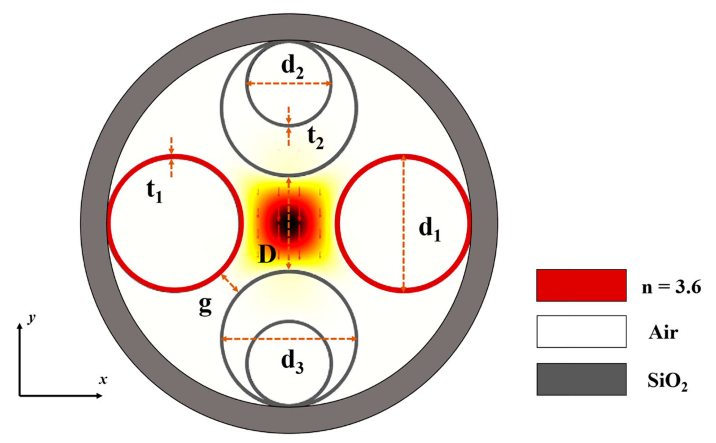
2. Fiber Structure and Performance

The two polarization states of the fundamental mode (FM) in HC-ARF are almost independently controlled by the cladding structure along the horizontal and vertical directions, which provides a better understanding of the roles of each structure and a practical fiber design method. Therefore, the strategy adopted here is to adjust the structures in the orthogonal directions of the cladding, respectively, to regulate the PMs. The proposed typical four-tube structured HC-ARF with dual thicknesses and dual material properties is shown in Figure 1. In the x-axis direction, there are two single-ring cladding tubes (marked in red) with a diameter of d1 = 41 µm, a thickness of t1 = 1 µm, and a refractive index of n = 3.6. In the y-axis direction, there are two nested cladding tubes composed of large and small SiO2 tubes. The wall thickness of the nested tubes is t2 = 0.45 µm, the diameter of the small tubes is d2 = 25.5 µm, and the diameter of the large tube is d3 = 41 µm; the spacing between the four clad tubes is g = 7.8 µm. Four cladding tubes surround an air core with a diameter of D = 28 µm. Due to the functional relationships established among the parameters of the fiber model, the core diameter D, the diameter of the single-ring cladding tube d1, and the spacing between the cladding tubes g satisfy Formula (1).
d 1 = g D · sin ( π / 4 ) 2 · sin ( π / 4 ) 2 ,
The differences in the structures and wall thicknesses of the cladding tubes along the x and y axes are used to break the degeneracy of the FM. The high refractive index property of single-ring cladding tubes is used to reduce the transmission loss of the guided mode. The diameter of the fiber core is smaller than that of the cladding tubes, providing enough operating space for the CMs. Except for the single-ring tubes, the background material of other parts of the designed fiber is SiO2, and the refractive index at different wavelengths is determined by the Sellmeier equation. Simulations are performed using COMSOL Multiphysics with an optimized mesh size. Set a circle of perfectly matched layers outside the fiber to obtain the imaginary part of the effective refractive index.
There are two difficulties to overcome in achieving pure SPSM beam transmission in fiber: (1) breaking the degeneracy of the FM to ensure a sufficiently large difference in transmission constants between the two polarization states; (2) increasing the transmission loss of one FM polarization state and all HOMs. The proposed HC-ARF introduces cladding tubes with different structures and materials in the orthogonal directions of the cladding region. By exploiting the structural asymmetry of the fiber, the degeneracy of the FM is broken to achieve high birefringence.
The curves of the effective refractive index (neff) and refractive index difference (Δn) for the two PMs of the FM as a function of wavelength are shown in Figure 2. According to the calculation results, the x-polarization mode exhibits a higher neff than the y-polarization mode, as a substantial amount of energy flows into the two single-ring tubes in the x-polarization mode. The electric field diagrams of the two PMs are shown in the inset of Figure 2a. The optical wave energy flowing into the single-ring tubes is significantly higher than that in the nested tubes. In Figure 2b, Δn > 1.7 × 10⁻⁵ in the range of 1000~2100 nm and increases with wavelength. Obviously, the two PMs are no longer degenerate in the transmission window exceeding 1000 nm, indicating that the designed fiber achieves an excellent polarization-maintaining effect.
High birefringence polarization maintaining fibers also have fundamental limitations: due to the difference propagation constants of the two polarization states, polarization-mode dispersion cannot be eliminated, so it is necessary to retain transmission of only one polarization state. The transmission loss of HC-ARF is calculated by adding confinement loss (CL) and scattering loss (SSL), where CL is the main loss in optical transmission, representing the energy loss when light escapes from the fiber core to the cladding. It can be calculated by the following equation [27]:
C L [ dB / km ] = 40 π I m ( n e f f ) I n ( 10 ) λ [ m ] 10 3 ,
where Im(neff) is the imaginary part of the mode effective refractive index. The proportion of SSL is rather small, and the specific calculation details can be found in [13].
S S L [ dB / km ] = η F ( λ [ μ m ] λ 0 ) 3 ,
where F is the optical power overlap between the core mode and the silica core boundary, and η = 300, representing the calibration factor at a wavelength of λ0 = 1.55 µm.
The loss control of PMs can be achieved by changing the material properties of cladding tubes in the horizontal and vertical directions. This method mainly regulates the CL, but the loss characteristics in this article include both CL and SSL. Figure 3a compares the loss characteristics of the two PMs and the minimum loss of HOM. The loss of y-polarization mode remains around 9.3 dB/km in the range of 1000 nm to 1650 nm, with the lowest loss is 0.96 dB/km at 1300 nm, while x-polarization mode is approximately 500 dB/km in this range. In the range of 1750~2100 nm, the average loss of y-polarization mode is approximately 23.3 dB/km, while that of x-polarization mode is all greater than 1000 dB/km. Furthermore, the minimum losses of the four vector modes of the first-order mode group at various wavelengths are picked out and plotted. Within the range of 1000~1400 nm, the minimum losses of HOMs are all greater than 88 dB/km, and they are all above 858 dB/km within 1450~2100 nm. The PER and the minimum higher-order mode extinction ratio (HOMER) of the fiber are shown in Figure 3b. Obviously, the proposed fiber exhibits sufficiently large propagation constant and loss differences, enabling long-distance stable transmission of SPSM beams in a wide spectral range.
The electric fields (E) and transversal power flows (Pt) of the FM and 1st HOMs at 1550 nm are shown in Figure 4 to visualize the filtering effect of this modulation method on modes. Under the same metric, the Pt diagrams of each mode clearly describe the distribution of their energy in the fiber. It can be observed that most of the energy of HE11y is distributed in the core, with only a small portion leaking into the cladding. In contrast, most of the energy of HE11x leaks into the two high-refractive-index single-ring tubes, while very little energy leaks into the nested tubes along the y-direction. This indicates that the high-refractive-index single-ring tubes have a significant impact on the loss of the x-polarization mode, which is crucial for realizing SPSM. Furthermore, the energy distribution of the 1st HOMs is also presented. The energy of these modes leaks out primarily through two pathways: one part leaks outward through the channels between cladding tubes due to the large spacing between the cladding tubes, and the other part is coupled into CMs, thereby leaking into the cladding tubes. The losses of these modes are labeled in the figure. Except for the y-polarization mode with a loss of 10.8 dB/km, the losses of all other modes are much higher than this value.

3. Optimization Process of SPSM

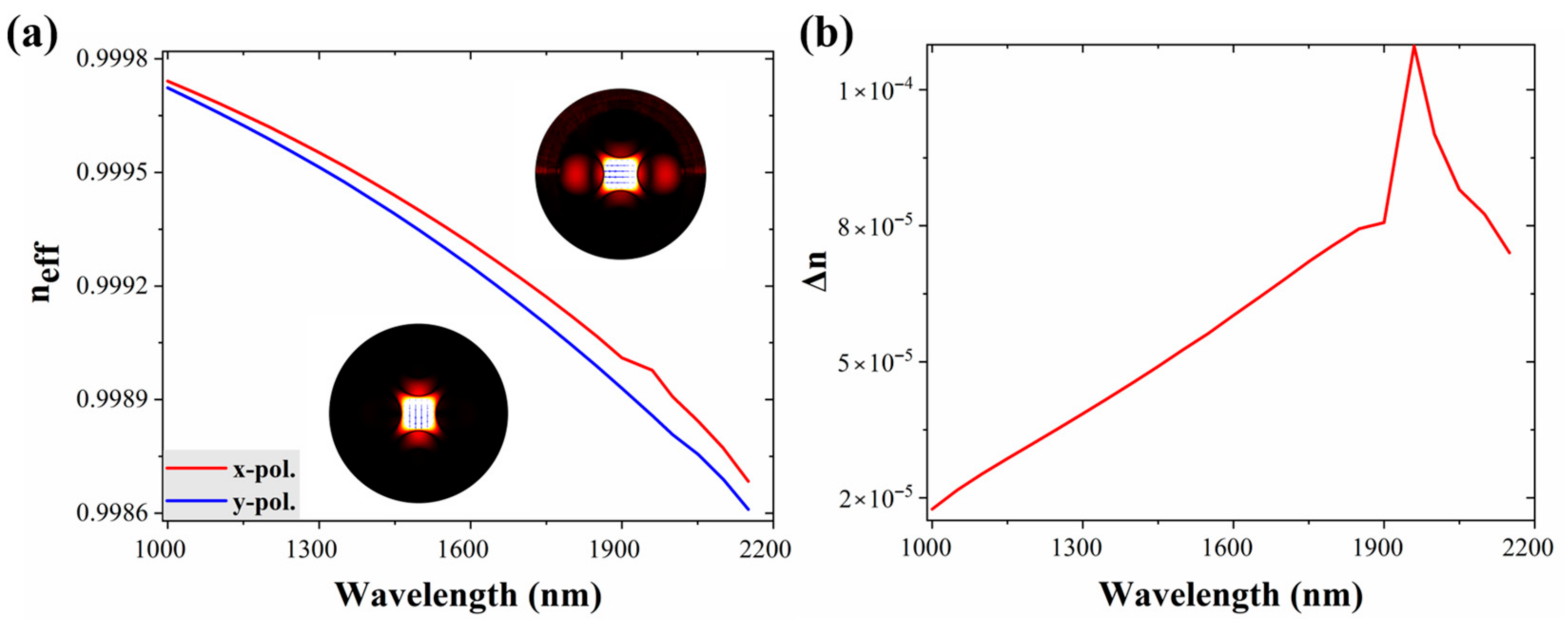
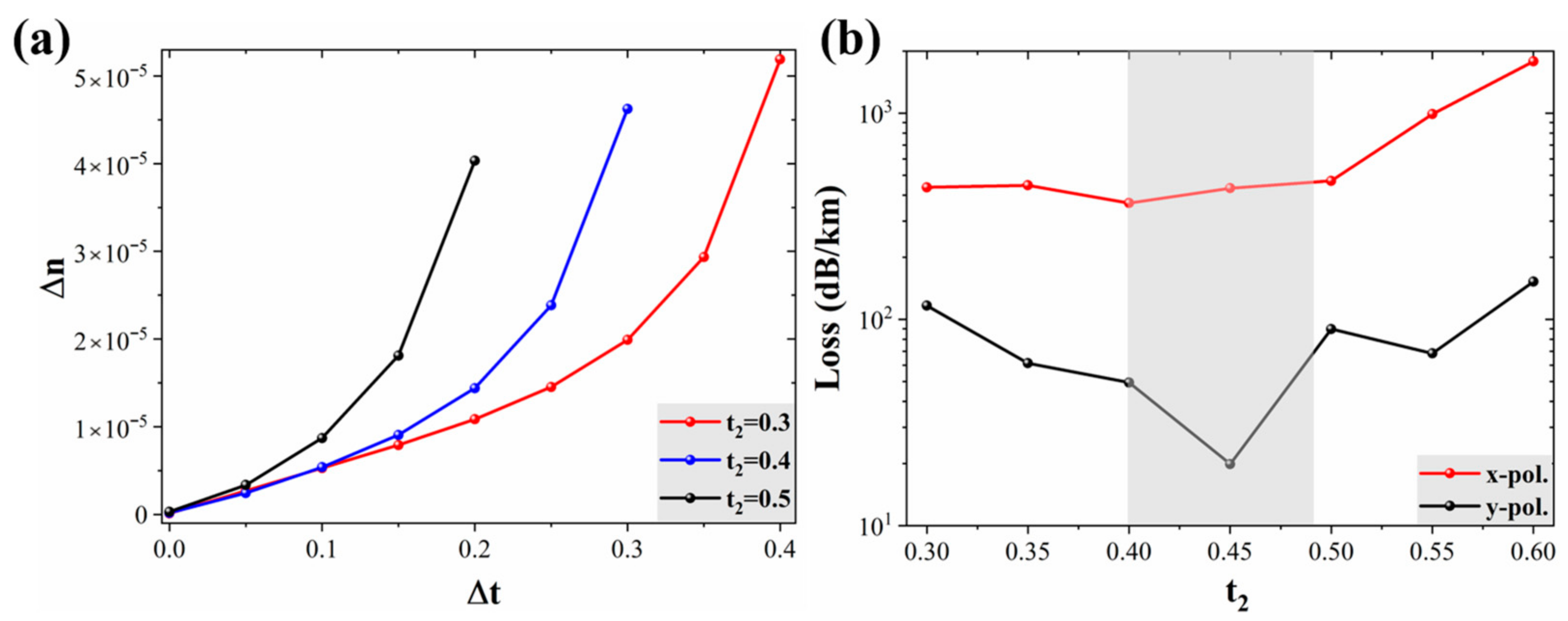
3.1. Optimization Process of Birefringence

Birefringence in HC-ARF can be achieved by introducing cladding tubes with different thicknesses in the orthogonal direction, that is, with uniform horizontal wall thickness and uniform vertical wall thickness, to break the degeneracy of the FM. The research here still starts from the 4-tube cladding structure composed of two single-ring tubes along the x-axis and two nested tubes along the y-axis. By changing t1 and t2, respectively, and analyzing the change rule of Δn in this process. As shown in Figure 5a, t2 is set to 0.3, 0.4, and 0.5, respectively, and then the value of t1 is scanned. The variation trend of Δn with Δt (t1t2) at a wavelength of 1550 nm is analyzed comparatively. Obviously, under the three different values of t2, Δn increases exponentially with the increase of t1, and the influence of Δt on Δn becomes more significant with increasing t2. This illustrates that the wall thickness difference in the orthogonal direction of the cladding tubes can provide a significantly large birefringence effect.
Scanning t1 provides an excellent design tool to find the highest possible birefringence at a single wavelength under the predetermined value of t2. However, the impact of the initial selection of t2 on polarization mode losses also needs to be considered to balance birefringence and loss. In Figure 5b, the influence of t2 on polarization mode loss when t2 ranges from 0.3 to 0.6 is further analyzed, with t1 always set equal to t2. The asymmetry of the cladding structure results in different loss characteristics for PMs. The x-polarization mode has a large loss, while the y-polarization mode has a relatively smaller loss due to the multiple anti-resonance effects of the nested tubes. When t2 is around 0.45, the y-polarization mode has the minimum loss and can maintain a high loss ratio with the x-polarization mode.

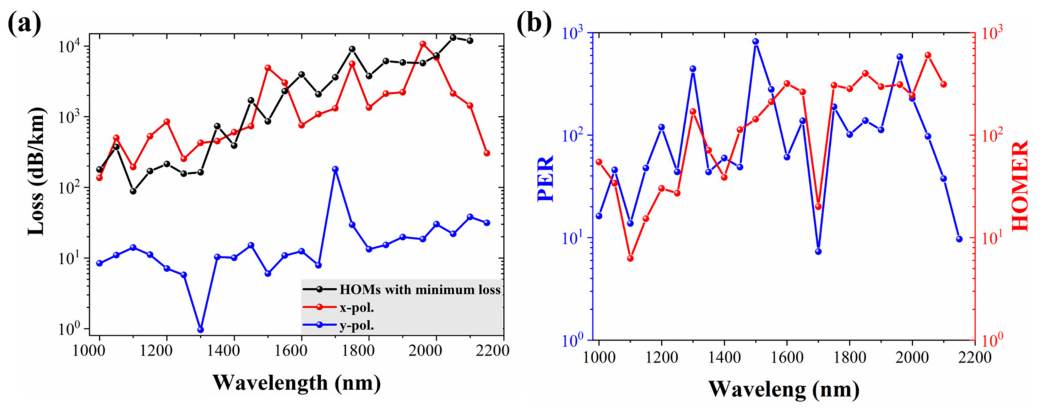
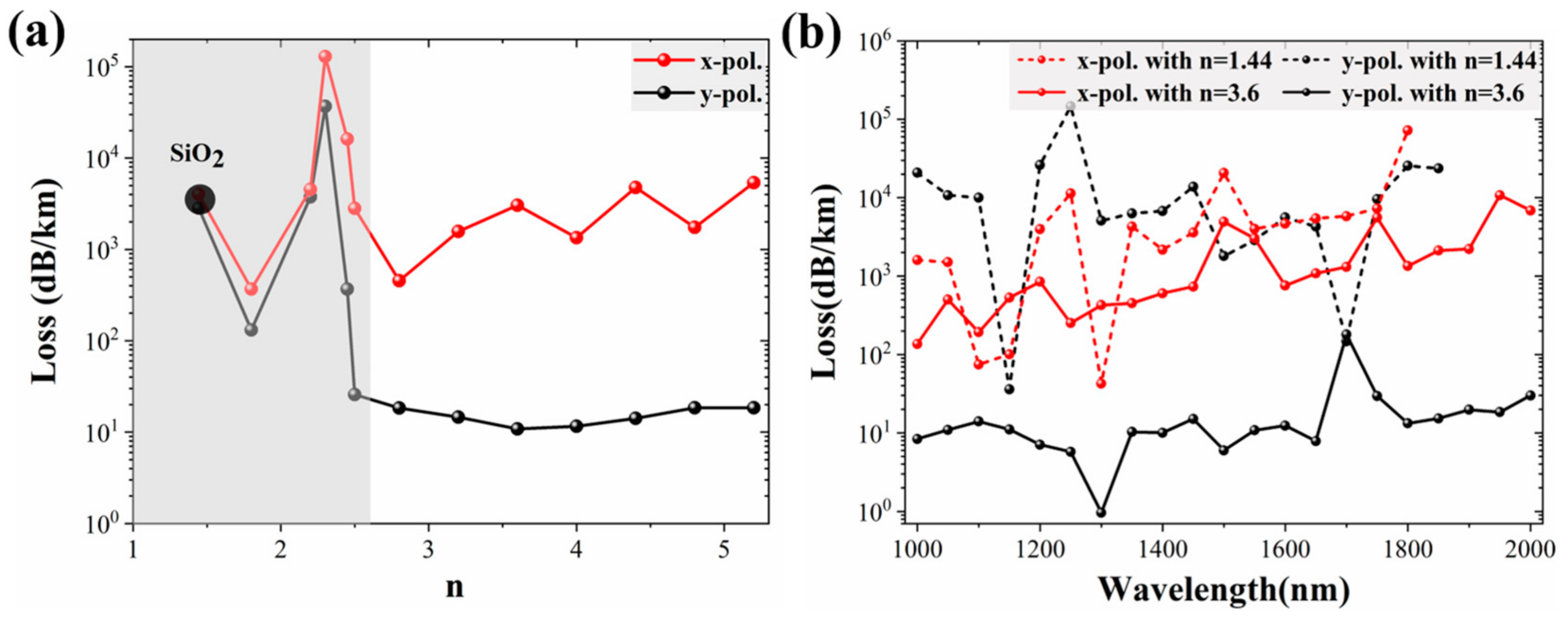
3.2. Optimization Process of Loss

Setting the wall thickness to an appropriate value can support stable transmission of the SPSM beam in the fiber core surrounded by SiO2 tubes, but the high loss characteristics still restrict the application scenarios of HC-ARFs. Due to the broad leakage channels in the four-ring cladding structure, while filtering out HOM energy, the structure also causes partial loss of FM energy, which is undesirable. This is because in the proposed fiber design, ensuring low loss and broadband transmission of the single polarization mode is also a key objective of the design. Considering the significant impact of fiber materials on mode loss, an attempt is made here to optimize the mode loss by changing the material properties of the single-ring cladding tubes.
Based on the above analysis of wall thickness, t1 is set to 1 µm and t2 to 0.45 µm. The material of the nested tubes remains SiO2, while only the refractive index (n) of the single-ring tubes is adjusted to observe the loss variations of the two PMs at a wavelength of 1550 nm. As shown in Figure 6a, the initial refractive index of the single-ring tubes is set to that of SiO2. With the gradual increases of n, both PMs exhibit high loss when n is 1.44~2.5. When n is 2.5~5.2, the loss of the y-polarization mode decreases to 6.4~26.7 dB/km, while the x-polarization mode still has a high loss of 1900 dB/km. Obviously, the two PMs have a sufficiently high loss ratio at 1550 nm to achieve an excellent SPSM effect. The achievable SPSM wavelength range of the fiber is further illustrated in Figure 6b, where the transmission spectra of the two PMs are compared for n is 1.44 (SiO2) and 3.6, respectively. The high refractive index of the single-ring tubes enables the y-polarization mode to maintain low loss over a wavelength range exceeding 1000 nm, without affecting the high-loss characteristics of the x-polarization mode. Therefore, the SPSM effect can be achieved over a sufficiently wide wavelength range by optimizing the refractive index of the single-ring cladding tubes.

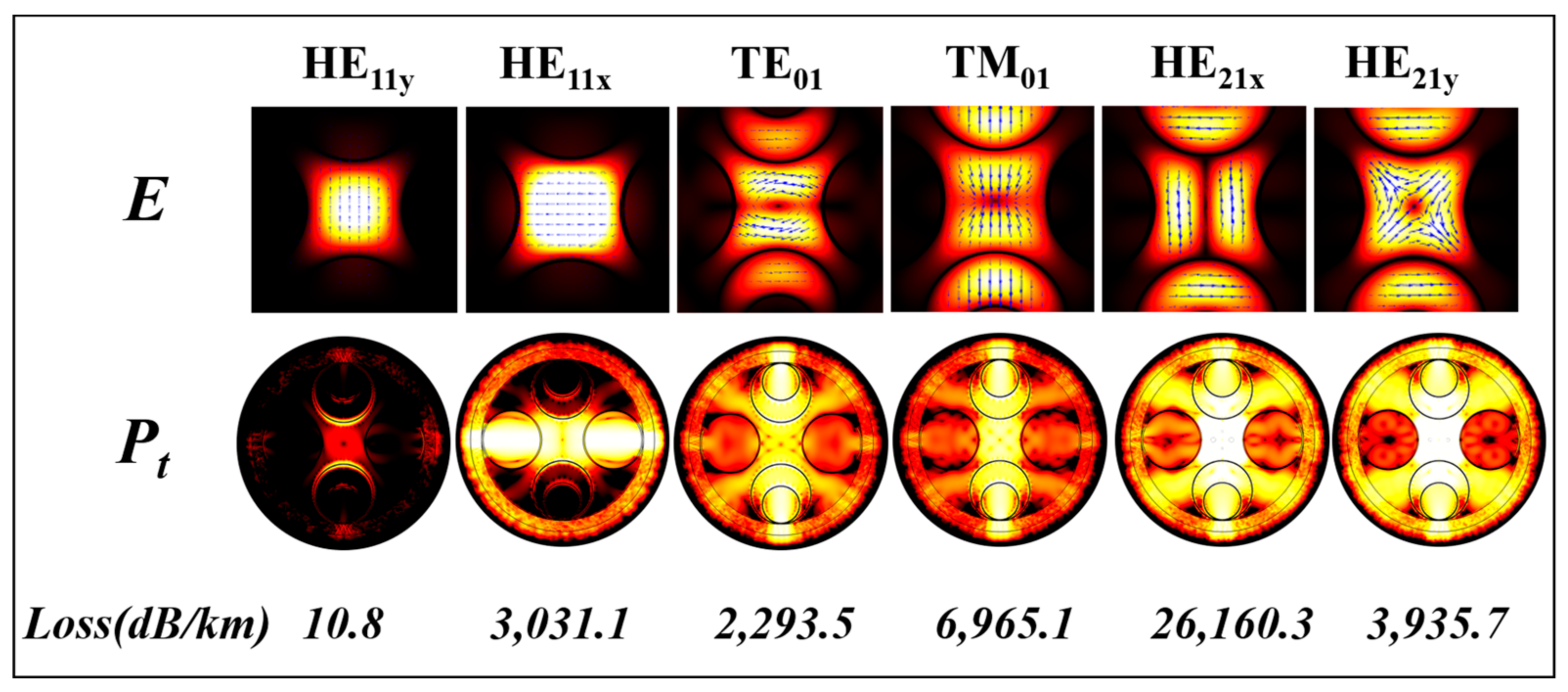
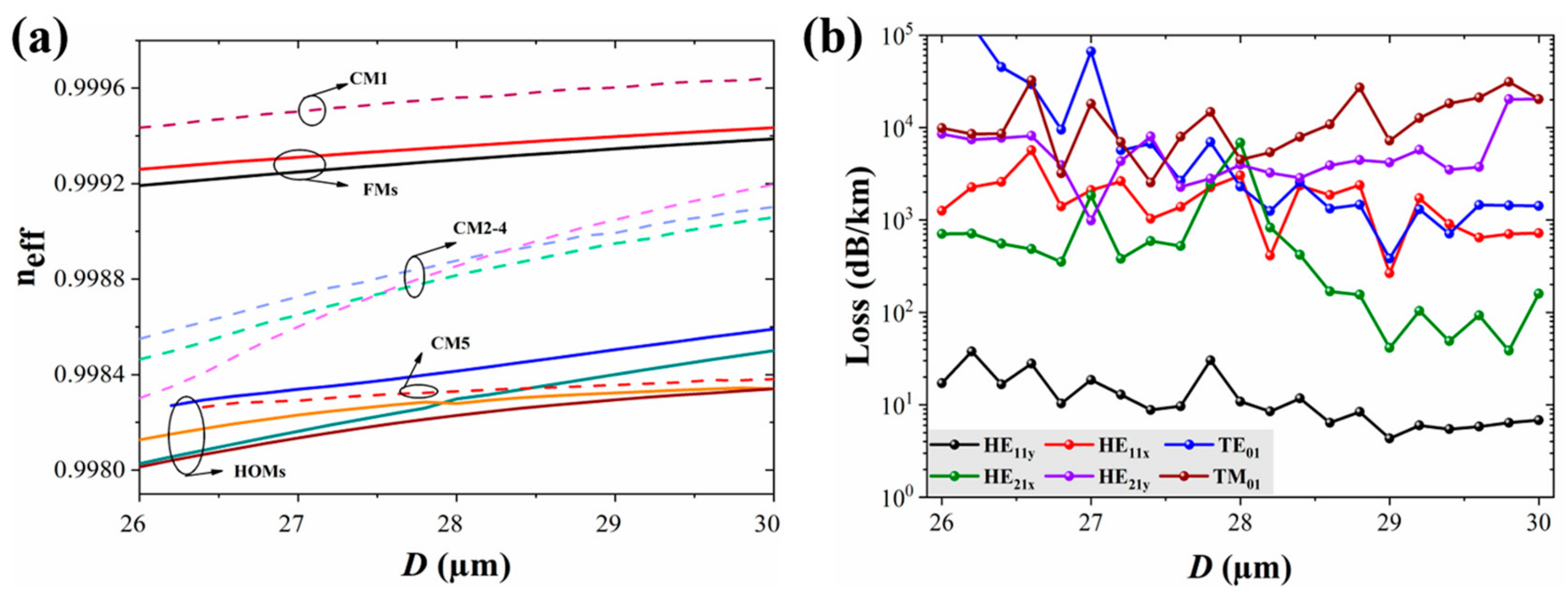
3.3. Optimization Process of HOM

The transmission of HOMs is inevitable in large-core fiber. Although most of the HOMs can be effectively stripped by the four-tube cladding structure due to its large tube spacing, some low-loss lower-order HOMs may still persist in the fiber core. To achieve purer SPSM characteristics, the cladding mode coupling mechanism can be introduced into the proposed HC-ARF structure with dual thickness and dual material properties. Due to the functional relationship between the parameters of the fiber model, D and d1 satisfy the proportional relationship of Formula (1). Therefore, D is taken as the control variable herein to analyze the characteristic changes of the first-order HOMs and the first five CMs at 1550 nm.
The variations in their neff are plotted in Figure 7a to demonstrate the coupling conditions between these two types of modes. Under the four-tube asymmetric cladding structure, the four vector modes of the first-order mode group are no longer degenerate. Due to the close neff of the two PMs, modulating them using the coupling effect of CMs is challenging. Therefore, CM1 and CM2–4 are kept as far from the FMs as possible to minimize their impact on the FMs. In contrast, since SM5 has a similar neff to TE01, HE21x, HE21y, and TM01, it can be tuned to an appropriate position to further enhance the filtering effect on HOMs. As shown in Figure 7b, under the combined effects of filtering by large tube spacing and coupling with CMs, all HOMs exhibit high-loss characteristics. When 26 µm < D < 28 µm, the y-polarization has a loss ratio of more than approximately two orders of magnitude compared with other modes. When D > 28 µm, as D increases, the losses will decrease significantly. Therefore, setting D to 28 µm, y-polarization has the best loss difference compared to other modes, ensuring that the proposed fiber can achieve SPSM operation.

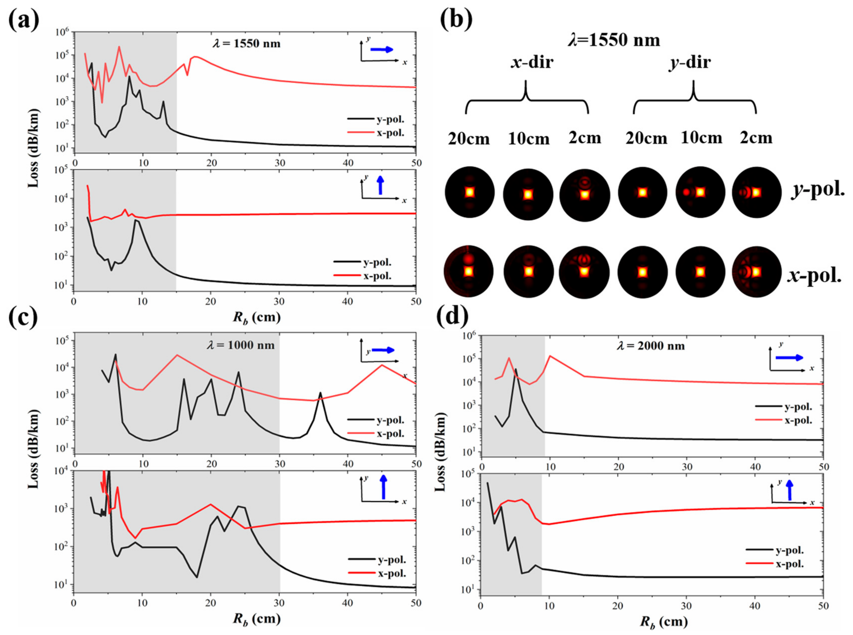
4. Bending Characteristics

The influence of external environmental disturbances and fiber crimping cannot be ignored in maintaining the stable polarization characteristics of fiber. Considering that the designed fiber has different cladding structures in the x and y directions, the bending characteristics will change with the variation of the bending direction. Here, a straight fiber with an equivalent refractive index is employed to simulate the bending loss. This approximation method is widely employed in HCF [22]:
n ( x , y ) = n 0 ( x , y ) [ 1 + ( x cos θ + x sin θ ) / R b ] ,
where Rb is the radius of curvature, x and y are the transverse and longitudinal distances to the center of the fiber, n0 (x, y) is the original refractive index distribution of the straight fiber and n (x, y) is the equivalent refractive index distribution when the fiber is bent, θ is the angle of bending.
As shown in Figure 8, the loss variations of the PMs are presented when the fiber is bent in the x and y directions at 1000 nm, 1550 nm, and 2000 nm, respectively. The gray areas represent the high-loss region caused by fiber bending. Obviously, the ani-bending performance of the designed SPSM HC-ARF at long wavelengths is significantly better than that at shorter wavelengths. For example, the anti-radii at three typical wavelengths of 1000 nm, 1550 nm, and 2000 nm are 30 cm, 15 cm, and 10 cm, respectively. This means that when the bending radius (Rb) at these wavelengths is smaller than the corresponding values, the bending loss of the polarization mode will increase substantially, and the mode will be coupled with more CMs.
Moreover, the mode field variations of x-polarization and y-polarization modes at 1550 nm with bending radii of 20 cm, 10 cm, and 2 cm are also plotted in Figure 8b. Due to the existence of many CMs in the cladding tubes, CMs and PMs are prone to coupling under bending. In the x-bending direction, when Rb < 15 cm, the PMs will successively couple with the CMs in the cladding tubes. Such as when Rb = 13 cm, the CM in the single-ring cladding tube couples with the y-polarization mode, causing high transmission loss. When Rb = 8 cm, the CM in the single-ring cladding tube couples with the y-polarization mode again. It is only when Rb = 4 cm that the loss of y-polarization begins to increase significantly due to the fiber bending. In the y-bending direction, due to the smaller size of the nested cladding tube, there are fewer coupling opportunities between the CMs and the PMs under the bent state. When Rb = 9 cm, the CM in the nested tube couples with the y-polarization mode. When Rb < 4 cm, the loss of the y-polarization mode increases significantly due to fiber bending. During the process of fiber bending, the x-polarization mode always has high loss characteristics and maintains a sufficiently high loss ratio with the y-polarization mode. Consequently, it can be concluded that the designed SPSM HC-ARF has stable bending resistance performance over a wide spectral range.

5. Discussion

  • Performance Comparison of Different SPSM HCF Designs
Table 1 provides an overview of the characteristics, such as birefringence, loss, and bandwidth of different HCF designs, and a direct comparison is made with the fiber design proposed in this paper. Compared with other structures of HCF, the designed HC-ARF with a four-tube cladding structure having dual thickness and dual material properties achieves a better balance in terms of bandwidth and loss. The low-loss SPSM wavelength range of up to 1000 nm is far beyond other similar fiber designs, and can be directly applied in application scenarios that are more relevant to other wavelengths.
B.
Selection of high refractive materials and Challenges of fiber drawing
In the fiber design, the single-ring cladding tubes possess high refractive index properties, which are a key design element for realizing low-loss SPSM transmission. In Figure 6, setting the refractive index within the range of 2.5~5.2 enables low-loss transmission of the guided mode. Therefore, it is necessary to find a high refractive index material suitable for the fiber. Silicon is a typical high refractive index material in the near-infrared region, such as amorphous silicon hydride, whose refractive index is about 3.6 in the transmission window of 1000~2000 nm, which can well meet the requirements of this design [31].
The proposed SPSM HC-ARF has many unique optical properties due to its four-tube asymmetric cladding structure. However, a point of practical importance is to ensure that the proposed fiber can be fabricated. Due to the lack of a manufacturing process, we cannot conduct experimental processing and testing on this structure. All simulations are based on the widely accepted theory. Only a tiny modulation is applied to the structure based on the typical HC-ARF compared with the previous SPSM HC-ARF design, which not only ensures the smallest possible disturbance to the mode field surrounding the core but also reduces the difficulty of processing as well as the impact of manufacturing errors in strange structures.
The fabrication of HCFs using silicon is not uncommon [32,33]. For instance, capillaries with silicon layers are assembled into preforms, leveraging the characteristic that the melting point of SiO2 is higher than that of silicon to ensure sufficient adhesion at high temperatures. Here, silicon tubes can be directly used as independent cladding tube units and fabricated using the high-pressure chemical vapor deposition (HPCVD) method [34,35], enabling uniform and precise control over the tube thickness. It should be noted that during the simultaneous drawing of capillaries and silicon tubes, strict pressure control must be exercised over both materials to accurately achieve the corresponding tube thicknesses. In addition, the key structural parameters that have a significant impact on the characteristics, such as the core diameter, the thickness of the cladding tube, and the refractive index of the single-ring tube, are discussed in the optimization section above. They all have a large tolerance range, which can ensure the SPSM effect even in the face of large size errors in the process of fiber drawing.
C.
Application-driven requirements
The exceptional polarization-maintaining capability of HC-ARF is important for a host of polarization-sensitive applications, enabling substantial reductions in noise levels and enhancements in sensitivity. A typical example is the optical gyroscope for space applications, which can benefit from various aspects of HC-ARF—long length, low loss, high radiation resistance, and suppressed polarization noise [36]. However, intermodal interference in HC-ARFs can also induce instability in optic gyroscopes. In SCF, the polarization-maintaining property is accomplished by the exploitation of birefringence (Δn~10−4). For HC-ARF, due to the extremely weak interaction between optical modes and the fiber cladding, even weakly birefringent HC-ARF can exhibit significant polarization-maintaining effects. For example, a non-birefringent HC-ARF with loss as low as 0.28 dB/km (Δn~10−7) can also provide a PER up to ~70 dB [11], which is nearly two orders of magnitude better than the achievable PER in commercial polarization-maintaining fibers. The Δn of the fiber designed in this paper is greater than 1.7 × 10⁻⁵ within the wavelength range of 1000 nm to 2000 nm, which is superior to the standards proposed in [11]. Moreover, compared with other HC-ARFs that only exhibit birefringence effects [37,38], this fiber furthers one of the PMs, indicating that the designed fiber can realize remarkable polarization-maintaining performance. On the other hand, fiber loss is also a factor that cannot be ignored. When the loss is less than 50 dB/km, it is already sufficient for applications in many meter-scale interferometers. The designed fiber has a loss far lower than this requirement within the transmission bandwidth. Thus, the proposed SPSM HC-ARF will become a competitive candidate for interferometric sensing applications.

6. Conclusions

In conclusion, we proposed and numerically simulated an HC-ARF with dual thickness and dual material properties that only support SPSM low-loss transmission over a wide spectral range. The structure and background material of the four cladding tubes in the orthogonal direction are set separately to filter out all modes except the y-polarization mode. The cladding tubes feature single-ring and nested-ring structures, respectively, to achieve a high birefringence effect. The single-ring tubes adopt background materials with a high refractive index to reduce the transmission loss of the supported single polarization mode. The simulation results show that the proposed fiber supports low-loss SPSM transmission over a 1000 nm wavelength range. Within the 1000–2100 nm spectral window, the birefringence exceeds 1.7 × 10⁻⁵. The average loss of y-polarization is 9.3 dB/km within the range of 1000~1650 nm, while that of x-polarization is > 500 dB/km, within the range of 1750~2100 nm, the loss of y-polarization is 23.3 dB/km, while that of x-polarization is > 1000 dB/km. Under the dual effects of the large-spacing leakage channels and the CM coupling, HOMs are well stripped off. To have a clear understanding of the process of realizing the SPSM, the influence processes of the key structures of the fiber on birefringence and loss are demonstrated in detail. In addition, the drawing challenge of the proposed HC-ARF and the selection of high refractive materials are also discussed. The proposed fiber could be an attractive candidate for applications such as interferometric sensors.

Author Contributions

Methodology, W.L.; Software, S.Z. and J.W.; validation, Y.L. and H.S.; writing—review and editing, Y.Y. and H.Y.; funding acquisition, Y.Y. All authors have read and agreed to the published version of the manuscript.

Funding

This research was supported by National Natural Science Foundation of China (62405119); Open Fund of State Key Laboratory of Photonics and Communications (2025QZKF017).

Institutional Review Board Statement

This article does not involve ethical issues.

Informed Consent Statement

Not applicable.

Data Availability Statement

Data underlying the results presented in this paper are not publicly available but can be obtained from the authors upon reasonable request.

Conflicts of Interest

The authors declare no conflicts of interest.

References

  1. Terrel, M.A.; Digonnet, M.J.F.; Fan, S. Resonant fiber optic gyroscope using an air-core fiber. J. Light. Technol. 2011, 30, 931–937. [Google Scholar] [CrossRef]
  2. Livi, L.F.; Cappellini, G.; Diem, M.; Franchi, L.; Clivati, C.; Frittelli, M.; Fallani, L. Synthetic dimensions and spin-orbit coupling with an optical clock transition. Phys. Rev. Lett. 2016, 117, 220401. [Google Scholar] [CrossRef] [PubMed]
  3. Denisov, A.; Soto, M.A.; Thévenaz, L. Going beyond 1000000 resolved points in a Brillouin distributed fiber sensor: Theoretical analysis and experimental demonstration. Light: Sci. Appl. 2016, 5, e16074. [Google Scholar] [CrossRef] [PubMed]
  4. Zhang, F.; Lit, J.W. Temperature and strain sensitivity measurements of high-birefringent polarization-maintaining fibers. Appl. Opt. 1993, 32, 2213–2218. [Google Scholar]
  5. Iwatsuki, K.; Hotate, K.; Higashiguchi, M. Kerr effect in an optical passive ring-resonator gyro. J. Light. Technol. 1986, 4, 645–651. [Google Scholar] [CrossRef]
  6. Sanders, G.A.; Taranta, A.A.; Narayanan, C.; Numkam, F.E.; Abokhamis, M.S.; Strandjord, L.K.; Smiciklas, M.; Bradley, T.D.; Hayes, J.; Jasion, G.T.; et al. Hollow-core resonator fiber optic gyroscope using nodeless anti-resonant fiber. Opt. Lett. 2020, 46, 46–49. [Google Scholar] [CrossRef]
  7. Ding, M.; Fokoua, E.R.N.; Bradley, T.D.; Poletti, F.; Richardson, D.J.; Slavík, R. Finesse limits in hollow core fiber based Fabry-Perot interferometers. J. Light. Technol. 2021, 39, 4489–4495. [Google Scholar] [CrossRef]
  8. Chen, Y.; Petrovich, M.N.; Fokoua, E.N.; Adamu, A.I.; Hassan, M.R.A.; Sakr, H.; Slavík, R.; Gorajoobi, S.B.; Alonso, M.; Poletti, F. Hollow core DNANF optical fiber with <0.11 dB/km loss. In Proceedings of the Optical Fiber Communication Conference, San Diego, CA, USA, 24–28 March 2024; Optica Publishing Group: Washington, DC, USA, 2024. [Google Scholar]
  9. Tamura, Y.; Sakuma, H.; Morita, K.; Suzuki, M.; Yamamoto, Y.; Shimada, K. The first 0.14-dB/km loss optical fiber and its impact on submarine transmission. J. Light. Technol. 2018, 36, 44–49. [Google Scholar]
  10. Gladyshev, A.V.; Bufetov, I.A. Hollow-core design provides polarization purity. Nat. Photonics 2020, 14, 468–469. [Google Scholar] [CrossRef]
  11. Taranta, A.; Numkam, F.E.; Abokhamis, M.S.; Hayes, J.R.; Bradley, T.D.; Jasion, G.T.; Poletti, F. Exceptional polarization purity in antiresonant hollow-core optical fibres. Nat. Photonics 2020, 14, 504–510. [Google Scholar]
  12. Fini, J.M.; Nicholson, J.W.; Windeler, R.S.; Monberg, E.M.; Meng, L.L.; Mangan, B.; Desantolo, A.; DiMarcello, F.V. Low-loss hollow-core fibers with improved single-modedness. Opt. Express 2013, 21, 6233–6242. [Google Scholar]
  13. Poletti, F. Nested antiresonant nodeless hollow core fiber. Opt. Express 2014, 22, 23807–23828. [Google Scholar]
  14. Mulvad, H.C.H.; Abokhamis Mousavi, S.; Zuba, V.; Xu, L.; Sakr, H.; Bradley, T.D.; Hayes, J.R.; Jasion, G.T.; Fokoua, E.N.; Taranta, A.; et al. Kilowatt-average-power single-mode laser light transmission over kilometre-scale hollow-core fibre. Nat. Photonics 2022, 16, 448–453. [Google Scholar]
  15. Michaud-Belleau, V.; Numkam, F.E.; Bradley, T.D.; Hayes, J.R.; Chen, Y.; Poletti, F.; Richardson, D.J.; Genest, J.; Slavík, R. Backscattering in antiresonant hollow-core fibers: Over 40 dB lower than in standard optical fibers. Optica 2021, 8, 216–219. [Google Scholar]
  16. Poggiolini, P.; Poletti, F. Opportunities and challenges for long-distance transmission in hollow-core fibres. J. Light. Technol. 2022, 40, 1605–1616. [Google Scholar]
  17. Habib, M.S.; Antonio-Lopez, J.E.; Markos, C.; Schülzgen, A.; Amezcua-Correa, R. Single-mode, low loss hollow-core anti-resonant fiber designs. Opt. Express 2019, 27, 3824–3836. [Google Scholar] [CrossRef]
  18. You, Y.; Guo, H.; Hao, Y.; Wang, Z.; Liu, Y.G. Wideband, large mode field and single vector mode transmission in a 37-cell hollow-core photonic bandgap fiber. Opt. Express 2021, 29, 24226–24236. [Google Scholar] [CrossRef]
  19. Yan, S.; Lou, S.; Zhang, W.; Lian, Z. Single-polarization single-mode double-ring hollow-core anti-resonant fiber. Opt. Express 2018, 26, 31160–31171. [Google Scholar]
  20. Yan, S.; Lian, Z.; Lou, S.; Wang, X.; Zhang, W.; Tang, Z. A new method to achieve single-polarization guidance in hollow-core negative-curvature fibers. IEEE Access 2020, 8, 53419–53426. [Google Scholar]
  21. Hong, Y.F.; Jia, A.Q.; Gao, S.F.; Sheng, Y.L.; Lu, Z.L.; Zhang, Z.; Ding, W.; Wang, Y.Y. Birefringent, low loss, and broadband semi-tube anti-resonant hollow-core fiber. Opt. Lett. 2022, 48, 163–166. [Google Scholar]
  22. Wang, Y.; Zhang, X.; Chen, W.; Zhang, Q.; Yang, Y.; Li, M.C.; Yan, M.; Wang, T.Y. Highly birefringent anti-resonant hollow-core fiber with meniscoid nested structure. Opt. Express 2024, 32, 25292–25303. [Google Scholar] [CrossRef]
  23. Zhao, X.; Xiang, J.; Wu, X.; Li, Z.W. High birefringence, single-polarization, low loss hollow-core anti-resonant fibers. Opt. Express 2021, 29, 36273–36286. [Google Scholar] [CrossRef]
  24. Chen, J.; Peng, L.; Shi, Y.; Wu, Y.H.; Zhao, N.; Li, J.M.; Zhou, G.Y.; Zhang, Q.M. Nested hollow-core anti-resonant fiber with elliptical cladding for 2 µm laser transmission. Opt. Express 2024, 32, 28148–28159. [Google Scholar] [CrossRef]
  25. Du, Z.; Zhou, Y.; Luo, S.; Zhang, Y.S.; Shao, J.; Guan, Z.G.; Yang, H.N.; Chen, D.R. Highly birefringent hollow-core anti-resonant terahertz fiber with a thin strut microstructure. Opt. Express 2022, 30, 3783–3792. [Google Scholar] [CrossRef]
  26. Mu, Q.; Zhu, Y.; Kong, D.; He, Z.; Liu, H.; Wang, L. Design, Simulation, and Characterization of a Partial Negative Curvature Antiresonant Hollow-Core Fiber for Low Loss Terahertz Wave Transmission. IEEE Trans. Terahertz Sci. Technol. 2024, 14, 510–518. [Google Scholar] [CrossRef]
  27. White, T.P.; Kuhlmey, B.T.; McPhedran, R.C.; Maystre, D.; Renversez, G.; De Sterke, C.M.; Botten, L.C. Multipole method for microstructured optical fibers. I. Formulation. J. Opt. Soc. Am. B 2002, 19, 2322–2330. [Google Scholar] [CrossRef]
  28. Zhu, Y.; Song, N.; Gao, F.; Xu, X. Single-polarization single-mode hollow-core photonic-bandgap fiber with thin slab waveguide. Opt. Express 2021, 29, 30371–30383. [Google Scholar] [CrossRef]
  29. Yan, S.; Lou, S.; Wang, X.; Zhao, T. Single-mode large-mode-area double-ring hollow-core anti-resonant fiber for high power delivery in mid-infrared region. Opt. Fiber Technol. 2018, 46, 118–124. [Google Scholar] [CrossRef]
  30. Habib, M.S.; Adamu, A.I.; Markos, C.; Amezcua-Correa, R. Enhanced birefringence in conventional and hybrid anti-resonant hollow-core fibers. Opt. Express 2021, 29, 12516–12530. [Google Scholar]
  31. Li, H.H. Refractive index of silicon and germanium and its wavelength and temperature derivatives. J. Phys. Chem. Ref. Data 1980, 9, 561–658. [Google Scholar] [CrossRef]
  32. Ballato, J.; Hawkins, T.; Foy, P.; Stolen, R.; Kokuoz, B.; Ellison, M.; McMillen, C.; Reppert, J.; Rao, A.M.; Daw, M.; et al. Silicon optical fiber. Opt. Express 2008, 16, 18675–18683. [Google Scholar] [CrossRef] [PubMed]
  33. Peacock, A.C.; Campling, J.; Runge, A.F.J.; Ren, H.; Shen, L.; Aktas, O.; Horak, P.; Healy, N.; Gibson, U.J.; Ballato, J. Wavelength conversion and supercontinuum generation in silicon optical fibers. IEEE J. Sel. Top. Quantum Electron. 2017, 24, 5100309. [Google Scholar]
  34. Sazio, P.J.A.; Amezcua-Correa, A.; Finlayson, C.E.; Hayes, J.R.; Scheidemantel, T.J.; Baril, N.F.; Jackson, B.R.; Won, D.J.; Zhang, F.; Margine, E.R.; et al. Microstructured optical fibers as high-pressure microfluidic reactors. Science 2006, 311, 1583–1586. [Google Scholar] [CrossRef]
  35. He, R.; Sazio, P.J.A.; Peacock, A.C.; Healy, N.; Sparks, J.R.; Krishnamurthi, M.; Venkatraman, G.; Badding, J.V. Integration of gigahertz-bandwidth semiconductor devices inside microstructured optical fibres. Nat. Photonics 2012, 6, 174–179. [Google Scholar] [CrossRef]
  36. Li, M.; Sun, Y.; Gao, S.; Zhao, X.; Hui, F.; Luo, W.; Hu, Q.B.; Chen, H.; Wu, H.L.; Wang, Y.Y.; et al. Navigation-grade interferometric air-core antiresonant fibre optic gyroscope with enhanced thermal stability. Nat. Commun. 2025, 16, 3449. [Google Scholar] [CrossRef]
  37. Mousavi, S.A.; Sandoghchi, S.R.; Richardson, D.J.; Poletti, F. Broadband high birefringence and polarizing hollow core antiresonant fibers. Opt. Express 2016, 24, 22943–22958. [Google Scholar] [CrossRef]
  38. Yerolatsitis, S.; Shurvinton, R.; Song, P.; Zhang, Y.; Francis-Jones, R.J.; Rusimova, K.R. Birefringent anti-resonant hollow-core fiber. J. Light. Technol. 2020, 38, 5157–5162. [Google Scholar] [CrossRef]
Figure 1. Cross-section structural parameters and schematic diagram of the proposed HC-ARF.
Photonics 12 00686 g001
Figure 2. Birefringence characteristics: (a) neff, and the inset shows the electric fields of two PMs, (b) Δn.
Photonics 12 00686 g002
Figure 3. Loss characteristics: (a) y-polarization and and other modes, (b) PER and HOMER.
Photonics 12 00686 g003
Figure 4. Electric fields (E), transversal power flows (Pt), and losses of the FM and 1st HOMs at 1550 nm.
Photonics 12 00686 g004
Figure 5. Birefringence optimization process at 1550 nm: (a) effect of Δt (t1t2) on Δn, (b) effect of t2 on polarization mode loss.
Photonics 12 00686 g005
Figure 6. Loss optimization process at 1550 nm: (a) influence of n on losses, (b) the loss spectra at n = 1.44 and 3.6.
Photonics 12 00686 g006
Figure 7. Influence of variations in D on 1st HOMs and some CMs at 1550 nm: (a) neff, (b) losses.
Photonics 12 00686 g007
Figure 8. Bending characteristics of the PMs in xy bending direction, the blue arrows indicate the bending direction. (a) 1550 nm, (b) the mode field diagrams at 1550 nm under different bending radii, (c) 1000 nm, (d) 2000 nm.
Photonics 12 00686 g008
Table 1. Summary of the characteristics of different SPSM HCF designs.
Ref.Wavelength (nm)BirefringenceBandwidth (nm)Loss (dB/km)PERBend Loss (dB/km)
[18] a1786~1840-50<0.5>1051.6 @ 1 cm
[28] a1440~1560>1.8 × 10−4120<43>10442 @ 9 mm
[29] b1545~1553≈10−4≈13≈40>104110 @ 8 cm
1591~1596
[30] b1053~1094≈10−441≈50>300≈ 60 @ 5 cm
[23] b1547~1552>6 × 10⁻⁵≈5<1≈104≈ 4 @ 5.8 cm
This work b1000~1650>1.7 × 10−51000≈9.3≈160≈ 22 @ 15 cm
1750~2100≈23.3
a HC-PBF; b HC-ARF.
Disclaimer/Publisher’s Note: The statements, opinions and data contained in all publications are solely those of the individual author(s) and contributor(s) and not of MDPI and/or the editor(s). MDPI and/or the editor(s) disclaim responsibility for any injury to people or property resulting from any ideas, methods, instructions or products referred to in the content.

