1. Introduction
Liquid crystals (LCs) represent a distinct state of matter that exists between the liquid and crystalline phases, combining the fluidity of liquids with the ordered molecular arrangement and anisotropic properties of crystals. Owing to these unique features, LCs have found widespread applications in the development of LC gratings, phase modulators, and displays. Seongyong Cho et al. proposed a tunable blue-phase LC grating in which blue-phase LCs are embedded within a polymer lattice. Under the influence of the electric field, the lattice constant of the grating can be modulated without altering the molecular alignment mode, enabling continuous tuning of the reflection wavelength. This type of grating shows potential for applications in tunable photonics and optical couplers in augmented reality systems [
1]. By infiltrating low-birefringence chiral LCs into a polymer lattice, cholesteric LC films can be fabricated. These films inherit the intrinsic reflective properties of cholesteric LCs along with the mechanical flexibility of polymers, making them suitable for flexible reflective displays, color pixels in digital photography, as well as printing and colored coatings for various objects [
2]. Notaros M. et al. developed an LC phase modulator that operates by applying an external electric field to the LC layer. This modulates the phase shift along the length of a silicon nitride waveguide by controlling the LC birefringence through molecular reorientation. Such a phase modulator can be utilized for dynamic displays and projection systems, underwater optical communications, and LiDAR sensing technologies [
3]. In the terahertz domain, the refractive index and birefringence of dual-frequency LCs can be tuned by continuously adjusting the frequency and amplitude of an alternating electric field. This tunability stems from the rotation of LC molecules induced by the alternating electric field. Experimental results have shown that a 600 μm thick LC cell can function as either a quarter-wave or half-wave plate across different frequency bands [
4]. Other researchers have explored the feasibility of using electrically tunable high-refractive-index wedge-shaped LC cells for edge imaging. Experimental evidence suggests that such LC cells can not only achieve broadband edge imaging but also enable real-time switching between edge-enhanced and original images through appropriate voltage control [
5]. Alex Hegyi et al. leveraged the controllable birefringence of LC layers to construct a hyperspectral imaging sensor resembling a Michelson interferometer. By modulating the relative optical path length between two beams of polarized light, the polarization state of the light passing through the LC can be interferometrically measured. This sensor stands out for its low cost, compact size, and simplicity, making it readily integrable into existing imaging sensor platforms [
6]. Alireza Moheghi et al. developed a novel polarizing light waveguide plate based on polymer-stabilized nematic LCs for LCD edge illumination. The waveguide plate enhances the optical efficiency of LCDs by converting unpolarized light into polarized light through selective scattering [
7].
The polarization state of electromagnetic waves, defined by the orientation, phase, and coherence of oscillation, plays a critical role in determining the nature of light-matter interactions. The transmission and scattering of light are fundamentally influenced by the polarization state of the incident light. Polarized light finds extensive applications in diverse fields such as interferometric measurements, logic gate operations, biomedical imaging, data storage, quantum communication, and quantum information processing [
8,
9,
10].
The refractive index and dielectric constant are key parameters characterizing the anisotropy of LC molecules. In applied optics and photonics, polarization control via external drivers is highly desirable for enhancing the flexibility of optical systems. Uan M. et al. investigated the polarization behavior of liquid crystal variable retarders operating in transmission mode under varying applied voltages. Their study focused on phase retardation, optical axis orientation, and depolarization effects in the output light. Accurate characterization of these polarization properties enables improved device performance and more reliable prediction of potential errors during operation [
11]. Richard L. Sutherland et al. examined the polarization characteristics of holographic polymer-dispersed liquid crystal (HPDLC) gratings, concluding that the variations in LC alignment distributions are the primary cause of differences in polarization behavior across diverse HPDLC gratings [
12]. By injecting nematic LCs into the gap between two equilateral prisms, an electrically tunable polarization beam splitter can be constructed. When voltage is applied, the device produces polarized output, whereas in the absence of an external voltage, the incident light is reflected by the LC layer without beam splitting. Such beam splitters offer advantages such as bistability, large splitting angles, broad fabrication tolerances, low cost, and ease of manufacturing [
8]. LC polarization gratings can also be employed to develop highly efficient polarization beam splitters. The anisotropic properties of LC materials used in these gratings can be electrically modulated. At present, photosensitive LC polymers and photoalignment techniques are widely adopted in the fabrication of such gratings [
13].
In addition to enabling the fabrication of beam splitters, LCs can also be used to manipulate the propagation direction of polarized light [
14,
15]. Polymer network-90° twisted nematic LCs allow linearly polarized light incident from one direction to pass through the twisted structure under an appropriate external voltage, resulting in an output beam with a polarization direction rotated by 90°. However, when the same linearly polarized light enters from the opposite direction, it encounters multiple LC domains with refractive index mismatches and is scattered as a result [
16]. By cascading two polymer LC polarization lenses with different diopters, a beam steering angle extender can be realized. This configuration enables continuous beam deflection when integrated with a small-angle steering mechanism [
17]. Yang Yanling et al. developed an achromatic polarization rotator composed of three twisted nematic LC cells. The polarization state of transmitted light can be controlled by modulating the orientation of LC molecules through applied voltage. Under voltage control, the device achieves a transmittance exceeding 97.9%, and its achromatic characteristics remain nearly unaffected when the LC cell thickness varies between 2.2 μm and 2.5 μm. This design achieves high contrast, excellent achromaticity, and fast response, fulfilling the performance requirements for polarization rotators [
18]. Some researchers have also combined asymmetrical pore array designs with electrically tunable polarization rotators using twisted nematic LCs. These devices can realize mixed color states by adjusting the polarization of incident light [
19].
A lot of commercial liquid crystal displays (LCDs) are based on twisted nematic (TN) or various super-twisted nematic (STN) effects, which have undergone extensive development and enhancement over the last 25 years and are still improving [
20,
21]. Modern liquid crystal materials and the advanced TFT-TN displays result in color displays of more than one million pixels [
21]. Under the action of burst driving voltage, the polarization-independent phase modulator can be made with 180° STN-LC [
22]. Light valves are devices that can be used to control the amount of light that passes through them or to protect privacy. By controlling the voltage applied to the dye-doped super-twisted nematic liquid crystal, the amount of light passing through it can be controlled so that the dye-doped super-twisted nematic liquid crystal can function as a light valve [
23].
Wu. S. T. and others developed a method using phase difference measurement technology, or the method of polarized light interference, to obtain the birefringence of liquid crystals [
24,
25,
26]. This technique’s uniqueness lies in its convenience, accuracy, and ability to measure the birefringence of liquid crystals at discrete wavelengths. However, this method relies on expensive instruments such as spectrometers, and the experimental procedures and data processing are relatively complex. The Abbe refractometer can measure the birefringence index of liquid crystals, but the space for placing objects is small, making it impossible to use large-volume temperature controllers for controlling the temperature of the tested liquid crystals [
27]. G. Pathak and others proposed a method to measure the birefringence of liquid crystals using transmittance technique [
28], which primarily involves equipment such as lasers, polarizers, photoelectric detectors, and digital storage oscilloscopes.
This study investigates the temperature-dependent polarization behavior of super-twisted nematic liquid crystals (STN-LCs) under laser illumination at wavelengths of 650 nm, 532 nm, and 405 nm. In addition, it explores a method for measuring and calculating the birefringence of STN-LCs using a simple optical setup. The findings provide methodological support for birefringence measurement in LCs and other anisotropic crystalline materials.
3. Temperature-Dependent Polarization Characterization of LC Cells
3.1. Polarization Characteristics of the LC Cell as a Function of Temperature Under Red Light Illumination
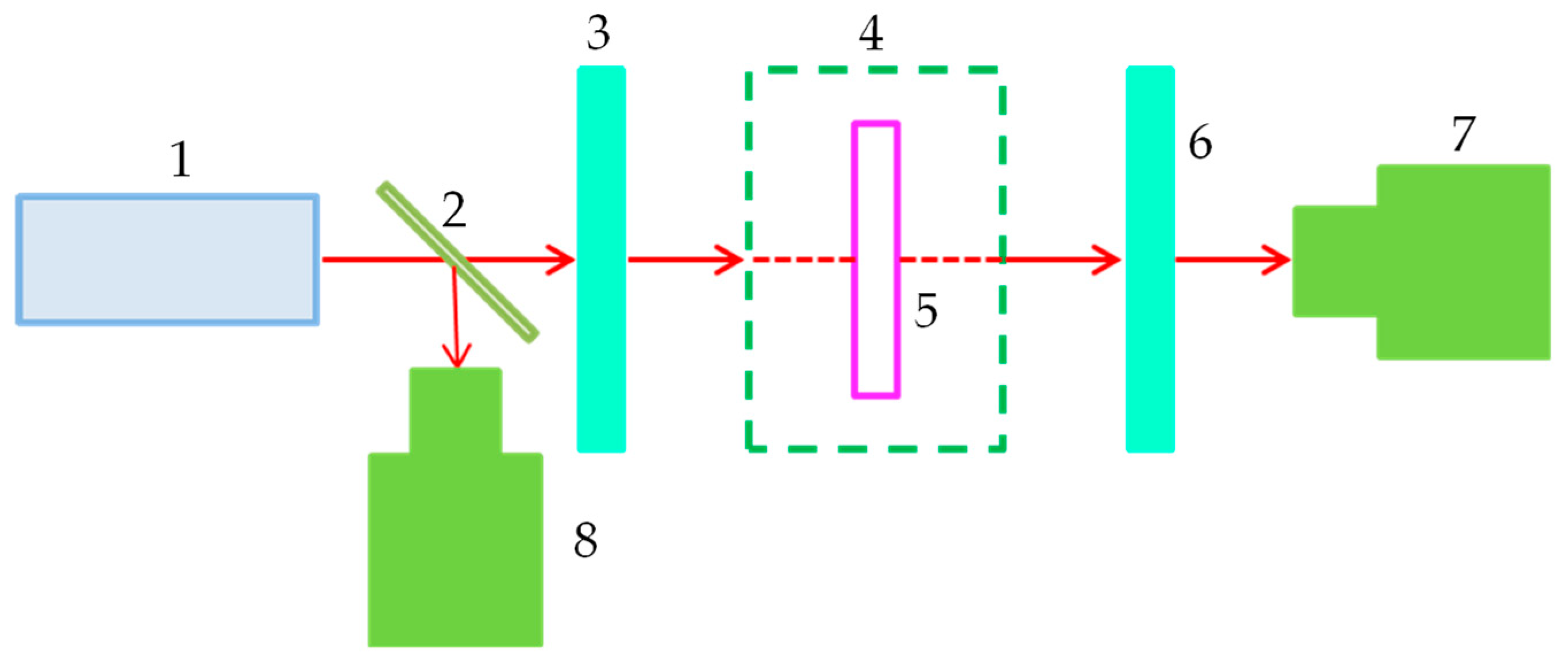
The experimental optical path is based on the optical path shown in
Figure 1, with a polarizer added in front of the LC cell. The incident light is perpendicular to the polarizer, and the incident surface of the LC cell is parallel to that of the polarizer. Both the LC cell and the polarizer were freely rotatable over a range of 0° to 360°. At room temperature, the LC cell was rotated to identify the angle at which the power measured by photodetector 5 in
Figure 1 reached a minimum, this position was defined as 0°, marking the initial angle
θ for LC cell rotation. During the experiment, the LC cell was rotated clockwise, with a fixed angular interval Δ
θ between successive measurements. After each measurement, the LC cell was returned to the 0° position. For clarity, this technique of measuring the polarization characteristics of the LC cell is referred to as the rotational measurement method in this study. In this setup, no analyzer (i.e., an additional polarizer) was placed after the LC cell. The LC cell functioned both as the device under test and as an analyzer. Linearly polarized light, after passing through the polarizer, entered the LC cell. If the LC layer possesses the characteristics of a linear polarizer, then rotating the LC cell through a full cycle should yield a transmittance curve consistent with Malus’s law. Otherwise, deviations from the ideal Malus’s law curve would indicate a departure from ideal linear polarization behavior. The rotational measurement method enables the characterization of the polarization properties and extinction ratio of the LC cell while also providing insights into molecular alignment distributions within the LC layer and whether the material behaves as a uniaxial crystal.
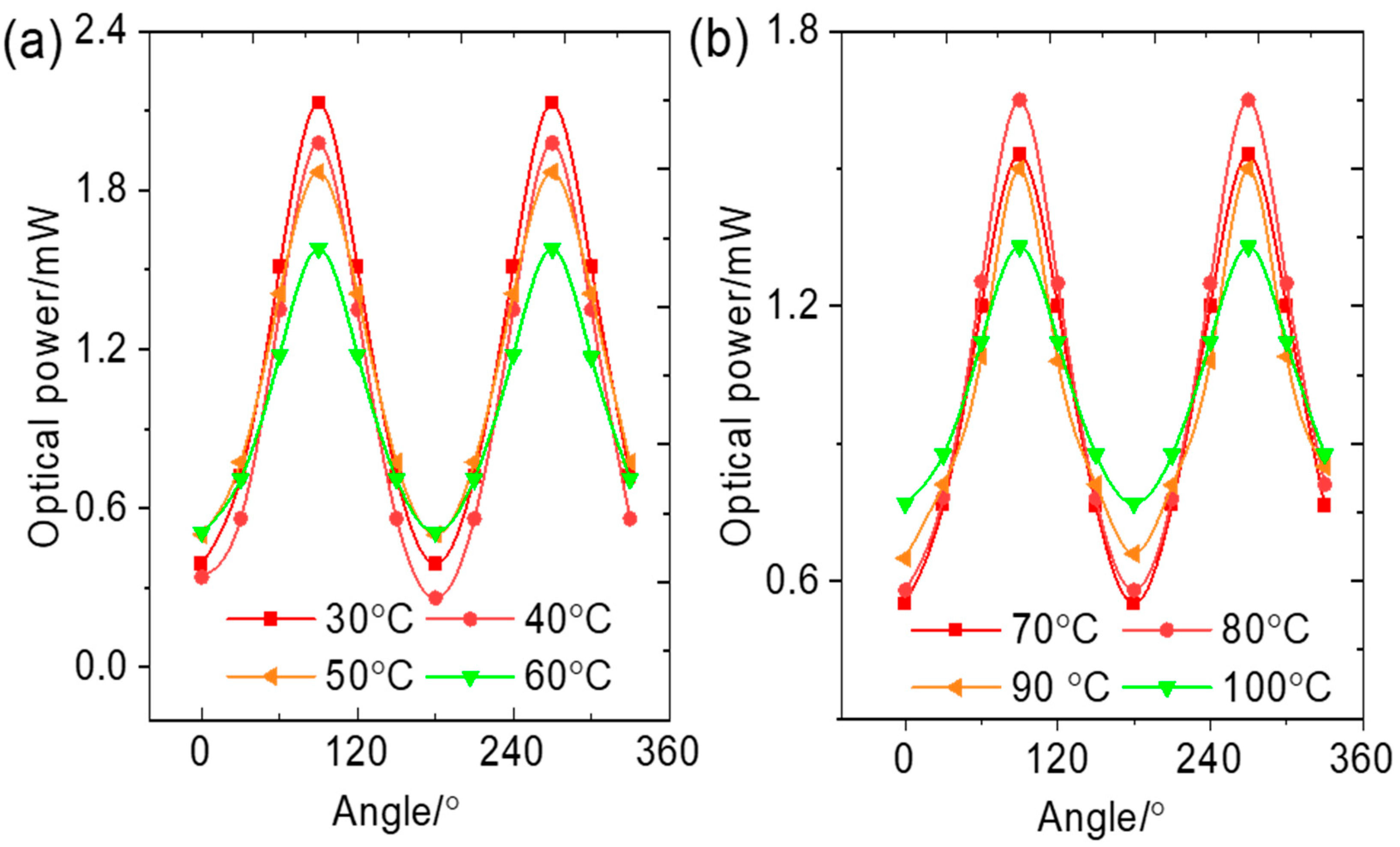
Figure 3 shows the relationship between the transmitted power of the LC cell and the rotation angle, obtained via the rotational measurement method. To eliminate the influence of fluctuations in laser output power, all power values in the curves were calibrated using data from the reference beam path. As shown in
Figure 3a, in the temperature range of 0 °C to 60 °C and under 650 nm red laser illumination, the extinction performance of the LC cell slightly deteriorates with increasing temperature, though the overall variation remains small.
One of the key indicators of the polarization performance of LCs is the extinction ratio. According to the literature, the polarization extinction ratio of LC cells can be calculated using the following formula:
where
Imin and
Imax represent the minimum and maximum light intensities of transmitted beam, respectively. Under 650 nm illumination at 30 °C, the extinction ratio of the LC cell is 0.034. At 40 °C, 50 °C, and 60 °C, the extinction ratios increase slightly to 0.039, 0.046, and 0.040, respectively, indicating a minor deterioration in extinction performance with rising temperature, although the variation remains minimal. In the temperature range of 30 °C to 60 °C, when the LC cell is rotated to 270°, the difference between the maximum and minimum transmitted power is 0.05 mW. Taking the average transmitted power value of 1.50 mW over a full 0–360° rotation as a reference, the maximum relative error in the fluctuation of transmitted power is 3.33%. Analysis of the experimental data further reveals a slight difference in transmitted power values between rotation angles of 90° and 270°.
In the temperature range of 70 °C to 100 °C, when the polarization direction of the LC cell is perpendicular to that of the polarizer, its extinction performance improves with increasing temperature, as shown in
Figure 3b. At 90 °C and 100 °C, the extinction ratio of the LC cell reaches 0, indicating a state of complete extinction.
Transmitted power is another important metric for evaluating whether the LC cell can function effectively as a polarizer. When the rotation angle θ of the LC cell is 90°, the transmitted power reaches a maximum of 1.53 mW at 100 °C. Under microscopic observation, the LC cell appears optically clear and transparent at this temperature. However, the LC layer inside the cell still retains its anisotropic nature, and its polarization performance remains excellent.
Overall, within the temperature range of 30 °C to 100 °C, the shape of the transmittance–temperature curve remains essentially unchanged. The transmittance values fluctuate only slightly within a narrow range, and the extinction ratio oscillates near 0. Therefore, when illuminated with a 650 nm red laser, the LC cell can effectively function as a polarizer throughout the entire temperature range.
3.2. Polarization Characteristics of the LC Cell as a Function of Temperature Under Green Laser Illumination
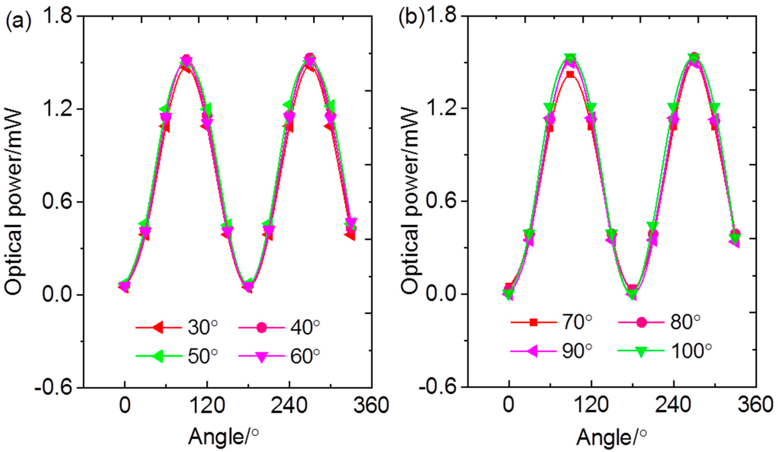
In this section, the 650 nm red laser used in §3.1 was replaced with a 532 nm green laser, while the experimental setup and measurement procedure remained unchanged. The resulting transmittance–temperature curves of the LC cell are displayed in
Figure 4. At 30 °C, when the polarizing direction of the polarizer is parallel to that of the LC cell (
θ = 90°), the measured optical power is 2.13 mW. As the LC cell is rotated through the full 0–360° range, the transmitted power curve follows a cosine-like trend.
As shown in
Figure 4a, the LC cell demonstrates polarization behavior characteristic of a uniaxial crystal at 30–60 °C. When the polarizer’s principal polarization direction is perpendicular to that of the LC cell (θ = 0°), the transmitted powers measured at 30 °C, 40 °C, 50 °C, and 60 °C are 0.39 mW, 0.39 mW, 0.50 mW, and 0.51 mW, respectively. The corresponding maximum transmitted powers at these temperatures are 2.13 mW, 1.98 mW, 1.94 mW, and 1.58 mW. Using the extinction ratio formula for polarizing devices (Equation (1)), the extinction ratios between the LC cell and the polarizer at 30 °C, 40 °C, 50 °C, and 60 °C are calculated to be 0.181, 0.195, 0.258, and 0.323, respectively. These results indicate that the LC cell achieves optimal extinction performance at 30 °C. In other words, under 532 nm green laser illumination, the LC cell functions most effectively as a polarizer at 30 °C.
At 60 °C, the liquid crystal cell has an extinction ratio greater than 0.3 and is not suitable to be used as a polarizer.
In the temperature range of 70 °C to 100 °C, the LC cell was rotated from 0° to 360°, with transmitted power measurements taken at 30° intervals. The results are presented in
Figure 4b. When the polarization direction of the polarizer is aligned with that of the LC cell, the transmitted powers recorded at 70 °C, 80 °C, 90 °C, and 100 °C are 1.53 mW, 1.65 mW, 1.50 mW, and 1.33 mW, respectively. The corresponding extinction ratios are 0.35, 0.35, 0.43, and 0.58. Clearly, the extinction ratio of the liquid crystal cell gradually increases as temperature rises, and at 100 °C, the extinction ratio even exceeds 0.5. As the temperature rises, the alignment of molecules in super-twisted nematic liquid crystals undergoes a transformation, accounting for the variation in the extinction ratio of liquid crystals as the temperature increases.
Within the temperature range of 70 °C to 100 °C, the average maximum transmitted power of the liquid crystal cell is 1.50 mW, while within the temperature range of 30 °C to 60 °C, the average maximum transmitted power is 1.91 mW. It can be seen that as the temperature increases, the overall trend of the transmitted power values is a decrease. In the temperature range of 70 °C to 100 °C, the curve between the transmission power and the rotation angle of the liquid crystal cell remains a cosine-like trend, and the liquid crystal cell still exhibits the polarization characteristics of a uniaxial crystal.
Analysis of the experimental data reveals that under 532 nm green laser illumination, the variation in transmitted power through the LC cell is markedly greater than that observed under 650 nm red laser. In the temperature range of 30 °C to 100 °C, the extinction ratio is always greater than 0.1, indicating poor extinction performance. When testing the polarization characteristics of liquid crystals using the rotational measurement method, important properties such as transmittance and extinction ratio can be obtained. This is of great significance for correctly understanding the molecular orientation distribution within the liquid crystal layer at a certain temperature.
3.3. Polarization Characteristics of the LC Cell as a Function of Temperature Under 405 nm Laser Illumination
In the experimental setup shown in
Figure 1, a 405 nm laser was employed as the light source. A polarizer was positioned in front of the LC cell, and the cell was rotated. The angle corresponding to the minimum transmitted power measured by photodetector 5 was defined as the starting position (0°). Transmitted power was then recorded at 30° intervals as the LC cell was rotated through a full 360°. The resulting relationship between transmitted power and temperature is presented in
Figure 5. As illustrated in
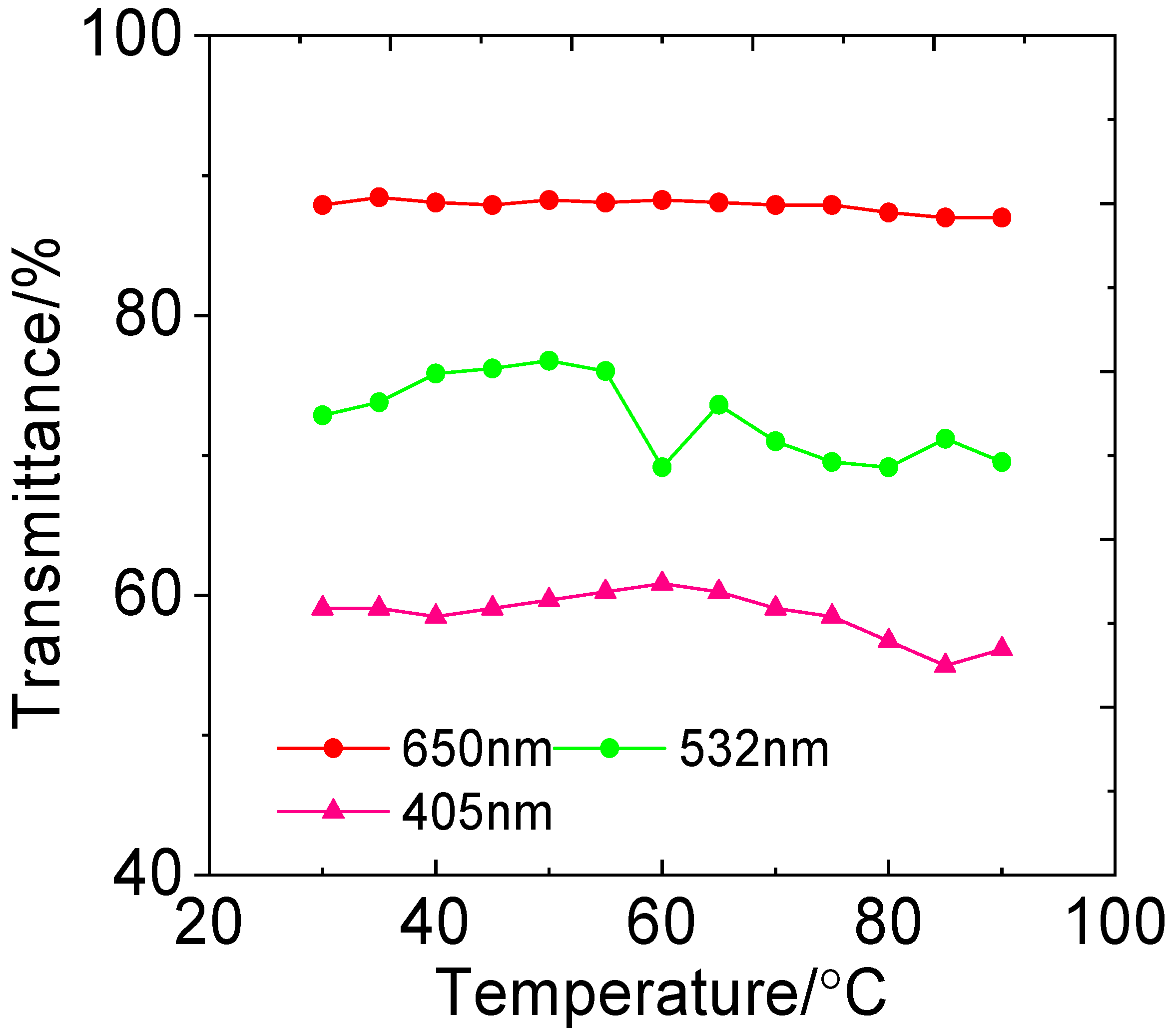
Figure 5a, at 30 °C, with increasing temperature, the overall transmitted power exhibits a decreasing trend; however, a local maximum of 0.32 mW is observed at 60 °C. When the polarization direction of the polarizer is perpendicular to the principal polarization axis of the LC cell, the transmitted power approaches 0. Using Equation (1), the extinction ratio at 60 °C is calculated to be 0.103. By comparison, the extinction ratio at the same temperature under 650 nm laser illumination is 0.040. This indicates that at 60 °C, the extinction performance of the LC cell is slightly inferior when illuminated with 405 nm light compared to 650 nm light.
In the temperature range of 70 °C to 100 °C, the relationship between the LC cell’s transmittance and temperature is shown in
Figure 5b. At 70 °C, the maximum transmitted power through the LC cell is 0.31 mW, which is nearly identical to the value observed at 60 °C. When the polarization direction of the polarizer is perpendicular to the principal polarization axis of the LC cell, the extinction ratio is 0, indicating excellent polarization performance and negligible depolarization effects. At 80 °C, when the principal polarization directions of the LC cell and the polarizer are aligned, the transmitted power decreases to 0.26 mW. However, as the temperature continues to increase, the transmitted power gradually rises, reaching 0.29 mW at 100 °C. At this temperature, the extinction ratio is 0.034, suggesting that the LC layer still exhibits polarization characteristics similar to those of a uniaxial crystal. The transmitted power–rotation angle curve is generally symmetrical between the angle range of 0–180° and 180–360°.
Within the temperature range of 30 °C to 100 °C, when using a 405 nm laser as the light source, the extinction ratio of the liquid crystal cell is slightly higher compared to when using a 650 nm laser as the light source. However, the extinction ratio values are all less than 0.1. The transmittance of the liquid crystal cell under a 405 nm light source is significantly lower than that under a 650 nm light source. Therefore, the liquid crystal cell used in this experiment is most suitable for use as a polarizer when illuminated with a 650 nm light source.
5. Conclusions
This study explored the transmittance of an STN-LC cell under laser illumination at wavelengths of 650 nm, 532 nm, and 405 nm. The measurement results show that the average transmittance is highest when the incident wavelength is 650 nm and lowest at 405 nm. For a given wavelength, the variation in transmittance with increasing temperature is relatively small. At room temperature, the STN-LC cell demonstrates good extinction performance under all three wavelengths, confirming its suitability for use as a linear polarizer. When illuminated with 650 nm and 405 nm lasers, the extinction ratio remains stable with rising temperature. It approaches 0 even at 100 °C, meaning that the STN-LC cell retains effective linear polarization characteristics under high-temperature conditions. However, under 532 nm illumination, the cell no longer functions effectively as a standard linear polarizer above 60 °C and exhibits multiaxial crystal-like polarization behavior at 100 °C. These findings indicate that the polarization characteristics of the STN-LC cell are strongly dependent on the wavelength of the incident light.
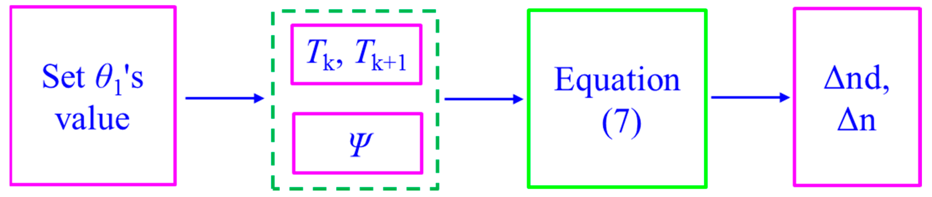
Based on the LC transmittance equation and the transmittance difference method, a formula was derived to calculate the birefringence of the LC layer. This method effectively circumvents the challenges posed by the unknown absorption effects of the glass substrates, which often obscure the intrinsic transmittance of the LC layer. When the LC layer thickness is known, based on experimental data obtained via the rotational measurement method, the birefringence can be accurately extracted using the transmittance difference method. This method requires only basic optical components, including a polarizer, the LC cell under test, a photodetector, and an optical power meter. This makes it both simple and cost-effective to implement, thus offering substantial potential for broader application.

