Article

Spectral Tuning and Angular–Gap Interrogation of Terahertz Spoof Surface Plasmon Resonances Excited on Rectangular Subwavelength Grating Using Attenuated Total Reflection in Otto Configuration

1
Research School of Physics, The Australian National University, Canberra, ACT 2601, Australia
2
Budker Institute of Nuclear Physics, Siberian Branch of RAS, Novosibirsk 630090, Russia
3
Department of Physics, Novosibirsk State University, Novosibirsk 630090, Russia
4
Synchrotron Radiation Facility SKIF, 1, pr. Nikolsky, Kol’tsovo 630559, Russia
5
Institute of Solid State Chemistry and Mechanochemistry, Siberian Branch of RAS, Novosibirsk 630090, Russia
*
Author to whom correspondence should be addressed.
Photonics 2025, 12(7), 651; https://doi.org/10.3390/photonics12070651 (registering DOI)
Submission received: 4 June 2025 / Revised: 13 June 2025 / Accepted: 24 June 2025 / Published: 26 June 2025
(This article belongs to the Special Issue Photonics Metamaterials: Processing and Applications)

Abstract

In this paper, we experimentally investigated the excitation of spoof surface plasmon polaritons (SSPPs) supported by a 1D subwavelength grating with a rectangular profile in the terahertz (THz) frequency range. Using the attenuated total reflection technique and the THz radiation of the Novosibirsk free electron laser, we carried out detailed studies of both angular and gap spectra at several wavelengths. A shallow grating supporting a fundamental mode was fabricated by means of multibeam X-ray lithography and used as a test sample. The results indicated that we achieved 1-THz tunability of resonance in the frequency range from 1.51 to 2.54 THz on a single grating, which cannot be obtained with active tunable metamaterials. The Q factors of the resonances in the angular spectra were within the range of 19.4–37.6, while the resonances of the gap spectra had a Q factor lying within the 1.17–2.03 range. The gap adjustment capability of the setup shown in the work has great potential in modulation of the absorption efficiency, whereas the angular tuning and recording data from each point of the grating will enable real-time monitoring of changes in the surrounding medium. All of this is highly important for enhanced terahertz real-time absorption spectroscopy and imaging.

1. Introduction

Surface plasmon polaritons (SPPs) are TM-polarised waves exponentially bound to a metal–dielectric interface and propagating along it. These kinds of waves have found widespread use in sensor and nonlinear applications in the visible and infrared spectral ranges due to their capability to field enhancement, light concentration, and sensitivity to minute changes of analyte [1,2,3]. However, the promising technological potential of SPPs on metals cannot be directly transferred to the terahertz (THz) frequency range (0.1–10 THz). Since surface waves arise from a collective oscillation of electrons, their existence is related to the negative dielectric permittivity of metals. Being an evanescent wave, SPPs penetrate into the metal to a distance referred to as the skin depth. In the optical range, a skin layer depth of about 15–30 nm can be observed with a similar penetration depth into the dielectric medium [4], whereas in the THz range the dielectric permittivity of metals increases significantly, leading to a slight excess of these values in metals (30–50 nm depth at 2 THz =150 µm) and a gigantic penetration depth into the space above them (the experimental value for gold is ≈5λ ≈ 750 µm) [5]. Thus, THz SPPs have low confinement near the surface and weak coupling (the proportion of the SPP energy carried in metals is much less than that in air), which results in their emitting into bulk waves at any slight roughness or optical inhomogeneities of the surface [6,7] and makes them virtually useless in the context of the above applications.
The coupling and confinement problems can be overcome with three effective approaches. First of all, it is possible to replace a metal material with semiconductors [8] or carbon materials, such as graphene [9]. At low frequencies, metals behave like a nearly perfect conductor due to the high density of electrons, while doped semiconductors or carbon nanoparticles can be considered as metallic systems, with the electron density significantly lower than that of metals. Moreover, their properties can be tuned via the doping density [10]. Another way to reduce the delocalization is to use metals with a thin dielectric coating. Such a multilayer system can be seen as a dielectric film waveguide, which has only the TM0 mode if the film thickness is in the deep subwavelength regime. This mode corresponds to surface plasmons, and using this method can increase their confinement by an order compared to a bare metal [6,11]. The third approach is related to subwavelength textured periodic structures on metal surfaces. In this case, the patterned metal supports surface modes, and its average response corresponds to that of an effective metal with a larger skin depth and lower dielectric permittivity. The excited surface waves on such metamaterials imitate well the properties of classical surface waves, having yet completely different dispersion relations, which depend on the geometry and material. Due to this similarity, they are called spoof surface plasmon polaritons (SSPPs) [12].
The high flexibility in manipulating and changing the properties of the SSPPs not only gave rise to various applications, but also made it possible to transfer some field concepts; for example, localised surface plasmon polaritons, from the visible range to the terahertz frequency one [13]. The experimental configurations for the implementation of the SSPP potentialities, mainly in sensing, include 1D subwavelength metal gratings, on which the SSPP resonance is excited with an attenuated total reflection setup. The first experimental demonstration of refractive index sensing of various fluids with this scheme was given in 2013. In 2014, Ng with his colleagues used the scattering edge coupling configuration to extract broadband dispersion data [14,15]. Since then, various scientists have conducted extensive numerical studies on the influence of various parameters on SSPP resonances and sensor capabilities of 1D subwavelength gratings in this scheme [16,17,18,19,20,21,22]. For instance, Yao H. and Zhong S. investigated the properties of high-order modes excited on subwavelength gratings [16], whereas Chen L. et al. demonstrated an analysis of their groove shape [19]. In another work [18], it was shown that by measuring the angular spectra, one can attain a high resolution for refractometry of substances. Further experimental works related to excitation of fundamental SSPP modes appeared in 2019 and 2020, when Huang et al. demonstrated the modulation of resonances via gap variation and realised a liquid sensor with direct phase readout capacity [23,24].
There have only been a few experimental works on the generation of spoof surface plasmon resonances on a subwavelength grating by the Otto method, where the time-domain spectroscopy (TDS) technique with broadband radiation sources was used. In the reflection spectrum, a resonant frequency corresponding to the resonance on the grating was observed, and refractometry of the substance surrounding the grating was performed based on the frequency shift. Despite the TDS method advantages, such as the possibility of simultaneous reconstruction of amplitude and phase spectra, there can be some disadvantages for SSPP sensing: (1) low spectral brightness (especially in the high-frequency region > 2 THz of the THz range for most TDS spectrometers), which complicates study of substances with absorption lines in this range; (2) numerical errors arising during spectrum reconstruction, which reduce the spectral resolution of the surface plasmon resonance (SPR) method; (3) not the entire spectral range of the source can be effectively used because of the subwavelength nature of the grating in relation to the wavelength; (4) excitation of SSPPs requires inducing THz waves with various incident angles at a certain frequency, which could be a challenge with the TDS method because of the need to adjust the optical path [25].
Recently, we made the first attempt to experimentally observe a plasmon resonance in the angular spectrum on a shallow subwavelength grating using a cylindrical silicon prism and monochromatic laser radiation [26]. The results showed poor resonance quality because of (1) the necessity to work near the critical angle (due to the high refractive index of silicon), which led to appearance of interference effects due to the leakage of some radiation from the prism; (2) the focusing properties of the cylindrical prism, which increased the dispersion of the incidence angles of radiation on the prism–air-grating interface; (3) a non-optimal system for recording the reflected signal. In this paper, we modify the experimental setup, taking into account the shortcomings of the first experiments. The new setup allowed us to suppress most of the side effects mentioned in the previous work and carry out detailed studies of both the angular and gap spectra at several wavelengths. A shallow grating supporting a fundamental mode was fabricated by means of multibeam X-ray lithography and used as a test sample.

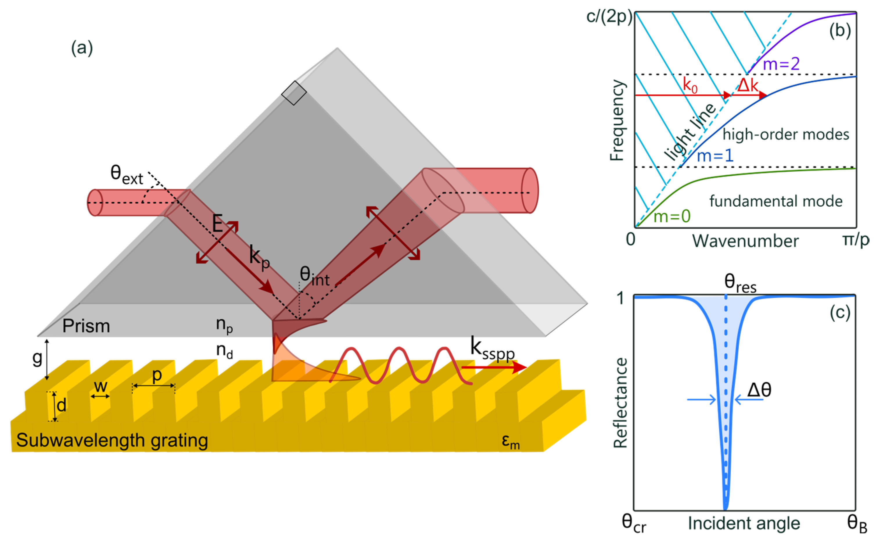
2. Theoretical Description

Many scientists have proposed descriptions of spoof surface plasmon polaritons excited on 1D subwavelength gratings using an effective medium and the mode matching technique [27,28,29,30,31,32]. We will use the theory written by Rusina et al. [29] for such structures with losses. In the framework of this consideration, a subwavelength grating (see Figure 1a) with period p, groove width w, and depth d satisfying the conditions p ,   w λ and w d can be described as a three-layer medium consisting of a homogeneous anisotropic layer with height d placed between metal and dielectric layers. The dispersion relation of SSPPs is as follows:
k S S P P = ε d k 0 2 + w ε d p ε g 2 · k g 2 t a n 2 k g d 1 2 ,
where k g = k 0 ε g 1 + l s i + 1 w 1 2 is the wave vector of the wave propagating in the groove; ε g and ε d is the dielectric permittivity of substance inside and outside grooves, respectively; k 0 = 2 π λ is the wavenumber of the wave in free space. This model takes into account the finite conductivity of the metal ε m via the skin depth l s = k 0 R e ε m 1 .
The typical dispersion relation is shown in Figure 1b. It exhibits high dependence on the width, depth, and period of the grooves, which provides flexibility in designing gratings for various applications. Among all these parameters, the depth has the greatest influence on the asymptotic frequency of spoof SPPs and excitation of the higher spoof plasmon modes, which can be seen as follows. If the higher-order mode exists, then the dispersion curve will intersect the light line, that is, k S S P P = ε d k 0 . This condition corresponds to t a n k g d = 0 and k g d = m π , where m = 0 ,   1 ,   2 , is the order of the spoof plasmon. The wavevector of the surface wave propagating along the corrugated surface is limited by the first Brillouin zone of k g < π p . Thus, clearly, modes with m 1 begin to be supported when d m p [31].
To excite a spoof plasmon, the incident wave must have a similar frequency and wavevector. However, for a given frequency, because of differing dispersion relations, the wavevector of a free-space wave is smaller than that of the SSPPs. This mismatch can be overcome with the attenuated total reflection technique. In this approach, a plane wave incident at the angle θ e x t onto a prism positioned against the subwavelength grating in the Otto configuration (see Figure 1a) creates an evanescent field from the prism surface at angles θ i n t greater than θ c r :
θ i n t > θ c r = a r c s i n n d / n p ,
where n p is the refractive index of the prism.
This field satisfies the spoof plasmon wave vector matching condition when
k S S P P = k 0 n p s i n θ i n t .
The coupling of the spoof plasmon affects not only the matching condition but also the gap between the prism and the subwavelength grating. In the first approximation, excitation of the mode appears when the evanescent wave from the prism overlaps with the mode of the subwavelength grating. This process is related to the penetration depths
l s s p p = 1 k S S P P 2 ε d k 0 2
of the spoof plasmon waves and
l p = 1 k 0 2 n p 2 s i n θ i n t ε d k 0 2
of the evanescent wave from the prism. As can be seen from Equation (4), l s s p p is smaller in the region above the surface for the higher operation frequencies due to the larger deviation of the parallel component of wavevector from the light line. In turn, l p (see Equation (5)) becomes smaller for prisms with higher refractive indices, which leads to higher confinement. The coupling process can be accompanied by side effects. If the prism is in close proximity to the grating, this significantly enhances the scattering and reflection between the prism and grating surfaces, which reduces the coupling efficiency, especially for strongly localised modes. On the contrary, a larger gap will result in a small overlap of the waves and poor coupling.
The coupling process can be explained precisely by the interference of the incident wave and reflected beam from the grating [33,34]. To our knowledge, this problem has not yet been analytically solved for the spoof surface plasmon polaritons excited on subwavelength gratings. However, we can draw on theoretical results developed for classical surface plasmon polaritons, assuming that the mechanisms for SSPPs are similar.
In this context, the transfer of the evanescent wave to the SSPPs is associated with losses in the system under consideration. On one hand, the resonance in the spectrum (see Figure 1c) can be described using a complex wavenumber, as follows [35,36,37]:
q r e s = q r e s + i q r e s = k 0 n p s i n θ r e s + i k 0 n p c o s θ r e s · Δ θ r e s ,  
where q r e s corresponds to the angle of minimum reflectivity, i.e., the phase matching condition, and q r e s is related to the losses and determines the halfwidth of the resonance Δ θ r e s .
On the other hand, the shape of the resonance is entirely determined by the characteristic of the spoof surface plasmon polaritons. The imaginary part of the wavenumber represents the damping rate of the SSPP, which consists of two damping mechanisms:
  • Internal damping ( q i ), associated with absorption in the metallic grating and proportional to the imaginary part of the effective dielectric constant.
  • Radiation damping ( q r ), arising from the emission of SSPPs into the prism, which depends on the gap between the prism and the grating.
It is expected that the critical coupling condition (corresponding to a minimum in the reflection spectrum) is achieved when the internal losses equal radiation losses that is q i = q r [35,36]. Furthermore, the influence of losses on the optimal gap can be understood in terms of SSPP skin depth into the grating. Lower internal losses result in a smaller skin depth and stronger localization of the spoof plasmon, thereby increasing the coupling between the SSPP and the incident wave. Consequently, a system with lower losses will exhibit a larger optimal gap.

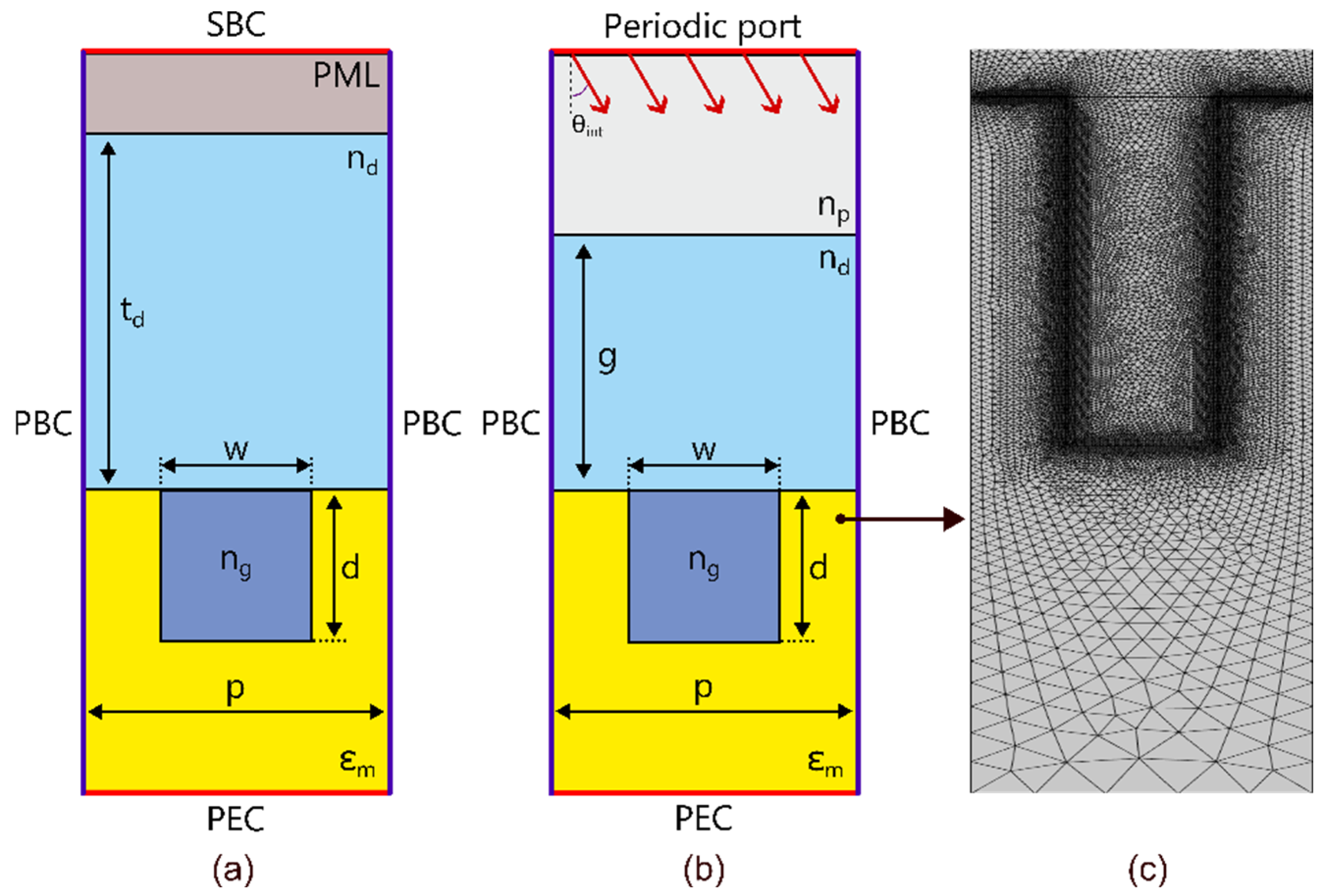
3. Numerical Simulation

The above theoretical model of SSPP on the grating is limited by the lack of consideration of diffraction of higher modes and interaction of fields arising above the grating grooves. These effects can be taken into account through either more rigorous, complicated theories [30] or a numerical simulation chosen as a basis. We performed numerical simulations using the finite difference method with the Radio Frequencies module of the commercially available COMSOL Multiphysics Software (version 6.0) [38]. The COMSOL eigenmode solver was applied to finding numerical dispersion curves, whereas the analysis of the reflection spectra was carried out with the frequency domain solver.
The numerical scheme for searching for eigenmodes is shown in Figure 2a. We calculated the dispersion curves of a 1D subwavelength grating with rectangular grooves infinite in the y-direction, which enabled us to use a 2D Floquet cell during the analysis. The right and left boundaries of the cell were limited by periodic boundary conditions, while the upper side was closed by a scattering boundary condition (SBC) with a perfect matched layer (PML) domain, and the lower one was defined as a perfect electric conductor (PEC). The SBC and the PEC almost did not affect the result of the simulation because of the high absorption of the grating and PML domains.
The x-component of the wavevector directed across the grooves varies, and an eigenmode is excited when k x coincides with the propagation constant of the spoof plasmon supported by the structure. The variation range was limited by the first Brillouin zone, that is, k x π p . The distance between the upper surface of the groove and the PML domain was large enough (greater than the penetration depth of the evanescent wave) to avoid the influence of the latter on the SSPP modes. The number of modes to be found was defined as M = 1 + d p , while the initial frequency for search resulted from solution to Equation (1). “Larger real part” was chosen as “the search method around shift” parameter.
The calculation of the reflection spectra was carried out using the numerical configuration consisting of the prism domain, dielectric gap, and grating shown in Figure 2b. As in the previous case, the left and right boundaries were periodic Floquet boundary conditions, but the wavevector magnitude was governed by the periodic port applied to the upper boundary. This boundary must not interact with the evanescent surface plasmon modes; thus, the prism domain size was large enough to allow waves from the port to propagate and reflect inside it. The remaining side was the PEC, which did not affect the response but made it possible to close the cell. The port excited a plane TM wave of H x H y H z = 0 0 1 . The electric field component was solved for the “in-plane vector.” The simulations were conducted at various angles θ i n t , frequencies, and gaps g. In both simulations, the permittivity of the metal was modeled with the Drude model
ε m = 1 ω p 2 ω 2 + i ω ω τ = 1 ω p 2 ω τ 2 ω 4 + ω 2 ω τ 2 + i ω p 2 ω τ ω ω 2 + ω τ 2 ,  
where ω τ is the electron-collision frequency, and ω p is the plasma frequency. The parameters of gold were ω τ = 4.05 · 10 13 rad/s and ω p = 1.37 · 10 16 rad/s [39]. For account of the metal loss and tiny skin depth, the mesh size at the metal–air interface was set to 100 nm and 300 nm as the minimum and maximum element sizes, respectively. The correctness of the definition of the mesh size around the metal–dielectric boundary significantly impacts the value of the optimal gap obtained in the simulation. The rest parameters of meshing were set to “extremely fine”, and the mesh was built automatically. The typical meshing around the metal–dielectric interface is shown in Figure 2c.

4. Fabrication Process

The process of rectangular grating fabrication consisted of two stages. At the first stage, we fabricated a rectangular grating using multibeam X-ray lithography in a manner similar to that described in the previous papers [40,41]. The gratings were embedded in a 50 × 50 × 10 mm polished glass substrate. The patterned area was 22 × 20 mm. The lithographic process used synchrotron radiation with energy in the range of 4–12 keV from the VEPP-3 electron storage ring, transmitted to the LIGA station of the Siberian Center of Synchrotron and Terahertz Radiation of Budker Institute of Nuclear Physics SB RAS [42].
The fabrication process was as follows. After wet cleaning in an aqueous solution of sulfuric acid, SU-8–100 photoresist layer about 50 µm thick was deposited by the centrifugation method and then dried on a hotplate. Then the photoresist layer was exposed to synchrotron radiation through a slit diaphragm with step-by-step motion of the substrate [43]. The exposure time depended on the required depth of the grating. This approach enabled quickly changing the design parameters through variation of the slit width and scanning speed. Once the photoresist layer had hardened on the hotplate at a temperature of 95 °C, liquid development of the photoresist layer was carried out in the PGMEA solvent.
At the second stage, a thin metal film was deposited on the patterned substrate using magnetron sputtering. The grating was covered with a 0.3 µm-thick gold (Au) layer with a 10 nm thick chromium sublayer, which was necessary to improve the adhesion of Au to the resist. Due to the small thickness of the Au layer, the geometric dimensions of the grating remained the same as before the sputtering. The choice of gold was due to its chemical inertness to the atmosphere and high conductivity. A fragment of the microstructure with a height and width of 14.5 ± 0.2 µm and period of 40 ± 0.1 µm is shown in the inserts of Figure 3.

5. Experimental Scheme

To excite SSPPs we built the experimental scheme shown in Figure 3. The Novosibirsk free electron laser (NovoFEL) [44] was used as a source of monochromatic terahertz radiation. The power of the incident p-polarised beam (E ⊥ grating grooves) was controlled using a metal wire polarizer, whereas its direction was governed by a system of mirrors. The beam splitter directed part of the beam energy to the laser power meter, which enabled detecting the current reference value of the power and tracking changes in the power during the experiment. The other part of the wave passed through the lithographic polarizer to be filtered from the parasitic s-polarised background (E || grating grooves). Then the beam impinged on the ZEONEX rectangular prism ( n p = 1.531 ) [45], transparent in both the THz and visible ranges. To adjust the 20-mm beam to the small size of the prism (≈7 mm), we used the 7-mm iris diaphragm placed near the prism. The incident angle exceeded the total internal reflection angle, resulting in the appearance of the evanescent wave interacting with the subwavelength grating. In our case, the relation between θ e x t and θ i n t can be calculated with Snell’s law as
θ i n t = 45 ° a s i n s i n 45 ° θ e x t 1 n p
in the assumption that the prism is surrounded by air. Therefore, the experimental angles were θ e x t > 38.56 ° and θ i n t > 40.8 ° . The beam reflected from the interface (prism–air–grating) was recorded using a TPX lens (f = 50 mm) in the 2f-2f configuration and a pyroelectric matrix detector (Pyrocam-IV) with a receiving area of 25 × 25 mm2 (320 × 320 pixels).
The subwavelength grating sample was attached to the optic mount at the distance g from the prism surface along the vertical axis. The motorised rotation stage (Standa) controlled the angular position of the prism with increments of 0.01 ° , while the vertical motorised stage (Standa) moved the gap with a step of 83 nm. The mechanically adjusted goniometer managed the parallel position of the prism surface and the subwavelength grating. The whole setup was adjusted using the red beam of the diode laser, combined with the THz beam.

6. Simulation Results

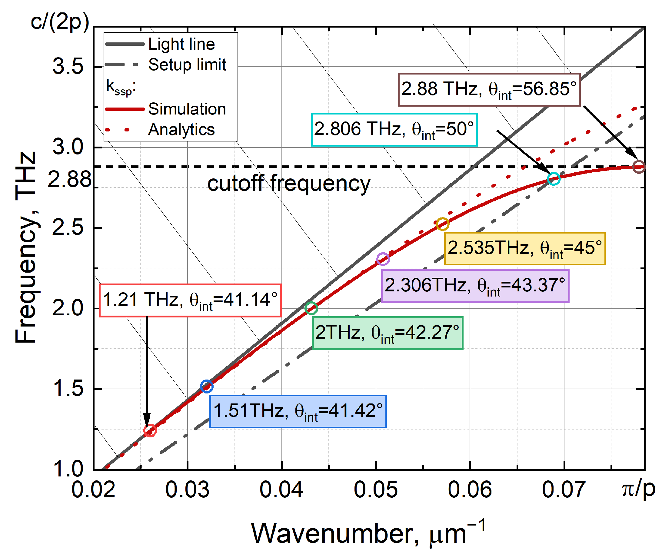
6.1. Dispersion Curve

The groove depth of our sample is 14.5 ± 0.2 μm, which is smaller than its period of 40 ± 0.1 μm, and thus it can support only the fundamental mode. The dispersion curves obtained with the simulation and Equation (1) are shown in Figure 4. As can be seen, a significant deviation of the analytical theory from the numerical results can be observed in the case of a shallow grating (w~d), as follows from the Rusina theory limitation (see the theory and numerical sections).
We conducted experiments in the vicinity of several frequencies and angles (see Figure 4). Their choice was determined by the atmospheric frequency transparency windows (in the absence of strong water vapor absorption lines) and the angles that can be adjusted with our in-house setup. The NovoFEL frequency can be tuned over a wide range (0.75–38 THz), but there are well-established operating regimes. Some of them correspond to 1.51 THz, 2 THz, 2.306 THz, and 2.535 THz. The range of angles covered by our setup is limited by both the prism size and the diameter of the incident beam. Due to this, the angle has to be between 40.8 (the ATR critical angle) and 50 degrees. The limited angular range has narrowed the operating frequency range to 1.21–2.806 THz. Both the frequencies and angles at which we work satisfy the matching condition (Equation (3)) and limitations of the setup.

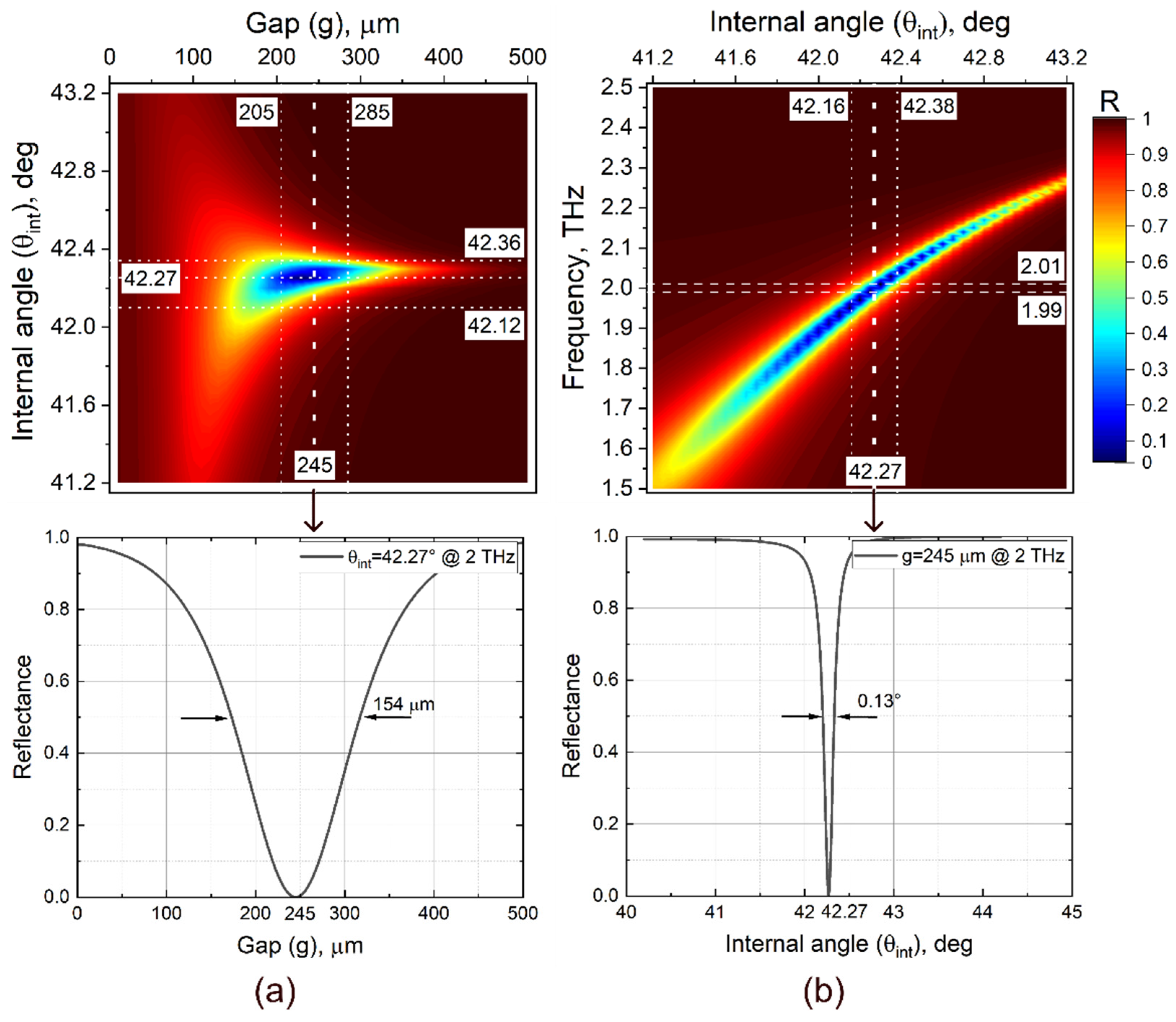
6.2. Gap and Frequency Variations

The gap between the grating and the prism base affects the efficiency of coupling of the evanescent wave into spoof surface plasmon polaritons. Through several simulations, we obtained gap–angular maps for the chosen excitation frequencies. One of the maps is shown in Figure 5a. By comparing the dip values of the reflectivity at the SPR points for different gap distances, we could find the optimal coupling distance. The optimal gap distance varies with the position on the dispersion curve, and the larger optimal gap corresponds to the closest position to the light line.
Although for many applications it is preferable to have a highly confined field, it requires more sophisticated experimental solutions in controlling the gap distance. In our setup, this complex task is not fully solved, which leads to the gap dispersion and zero gap error. Because of tilts, the gap distance varies for different points of the grating surface. This effect can be called gap dispersion. As a result, the SSPPs interact non-uniformly with the evanescent wave and are excited with different efficiencies. Another challenge is the difficulty of experimental determination of the zero position of the gap because of the mechanical adjustment prior to the experiment. The inaccuracy of the zero setting could be about 0–40 μm, while the tilt of the prism base could be ~0.2–0.3°, which leads to a gap dispersion of ~25–40 μm (see Figure 5a). All these effects can be eliminated by increasing the optimal gap distances in the experimental measurements and choosing the excitation points on the dispersion curves closer to the light line.
In the experiment, in addition to the gap dispersion, we have the spectral width of the laser. The NovoFEL radiation usually has a spectral width of ~1% of the central frequency [46]. For instance, if we have an excitation frequency of 2 THz, then the spectral width will be 0.02 THz. In addition, the beam incident on the prism has diffraction divergence. This means that the light will fall onto the prism at different angles, which leads to different efficiencies of excitations of SSPPs related to different points on the dispersion curves. This effect can be reflected with the frequency–angular map shown in Figure 5b.
To estimate the contribution of these effects, we will consider excitation of a spoof plasmon on the gold grating at 2 THz (150 μm). At this frequency, we have an optimal gap and an optimal angle, equal to 245 μm and 42.27°, respectively. The spectral width of the incident beam affects the optimal-coupling incident-angle broadening. Since we have a diaphragm diameter of 7 mm in the experiment, the diffraction angular spread will be ~ λ d = ± 1.2 ° . However, due to the relatively narrow spectral width of the beam, only angles lying in the range of ± 0.11 ° from the optimal one will contribute to the excitation process, as shown in Figure 5b. The angular components that do not interact with the grating will reduce the energy transferred into the spoof plasmons in the experiment. The gap dispersion enables more efficient coupling of different angular and frequency components of the beam, resulting in an almost twofold expansion of the angular spectrum width from 0.13° to 0.22°. The gap spectrum remains virtually unchanged due to its large width.

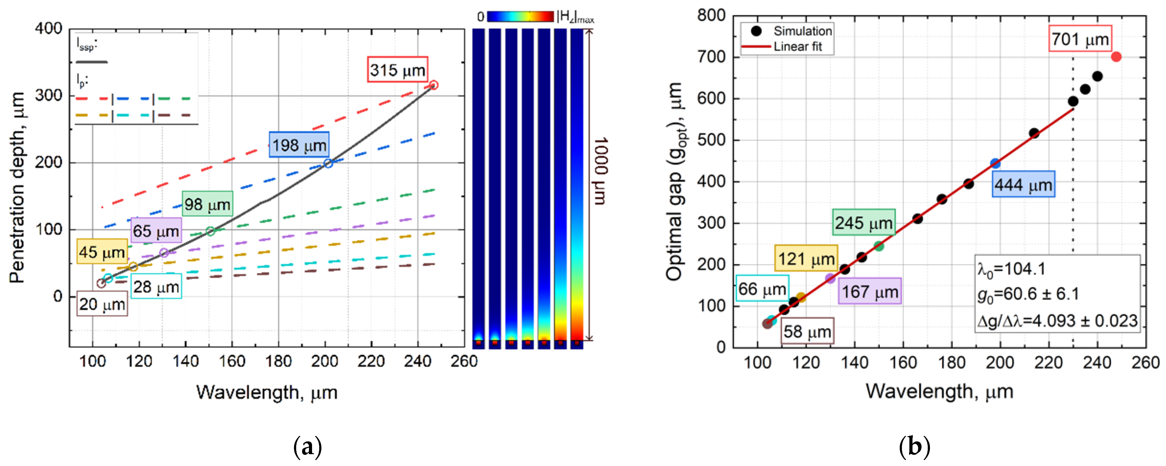
6.3. Field Confinement and Optimal Gap

The confinement of the electromagnetic field above the grooves is dependent on the position of the excited mode on the dispersion curve. According to Equation (4), the closer the wavenumber of the spoof plasmon to the Brillouin zone boundary, the better its confinement. We estimated the penetration depth of the spoof surface plasmon using Equation (4) and the numerical dispersion curve, as shown in Figure 6a. The value of l s s p p decreases relatively fast from 780 μm (≈3 λ) in the vicinity of the light line to 20 μm (≈0.2 λ) at the Brillouin zone boundary. Excitation of SSPPs occurs when the wave vector matching condition is met (see Equation (3)), which looks like the intersection of l p (see Equation (5)) with l s s p p .
However, the optimal gap is not equal to the SSPP penetration depth and cannot be fully described as an overlap of two evanescent waves when l p = l s s p p . It is associated with the appearance of additional reflection and interference effects, which result in a complicated interaction of the SSPP waves and the evanescent wave of the prism in the gap between the prism and the subwavelength grating. We conducted several simulations to find the optimal gaps at various wavelengths. The obtained dependence of the optimal gap on the wavelength is plotted in Figure 6b. To approximate it, we used the equation
g = g 0 + Δ g Δ λ λ λ 0 ,
where g 0 is the minimum gap corresponding to the cutoff wavelength, λ 0 is the cutoff wavelength, and Δ g Δ λ is the rate of gap variation with change in the wavelength. This approximation is valid up to the proximity to the light line, where transition effects occur and enable quick determination of the optimal coupling gap distance.

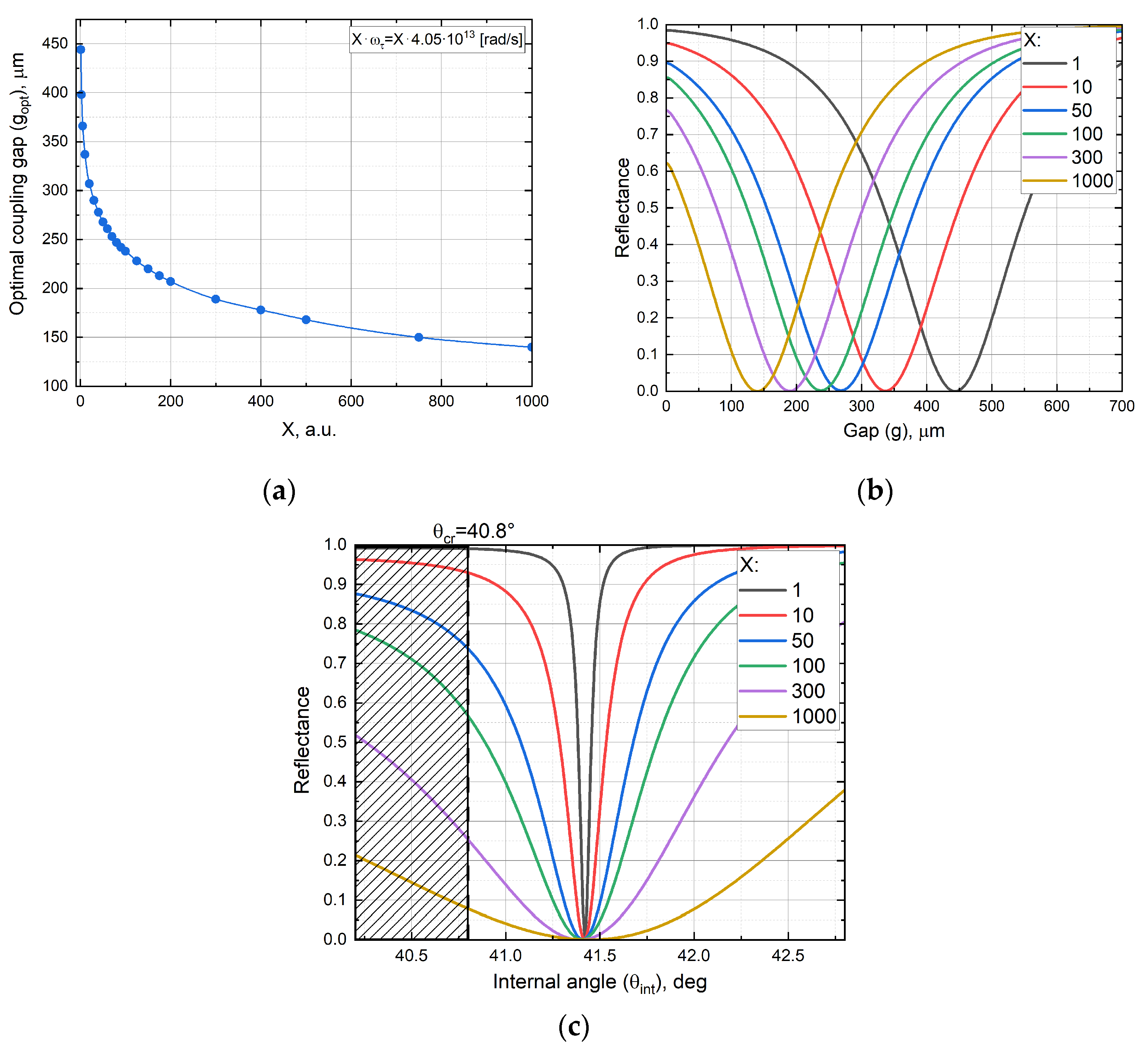
6.4. Losses and Optimal Gap

As mentioned in the theoretical section, the gap distance between the prism and the grating is influenced by losses in the system. To demonstrate this, we can consider two ways to increase internal losses: either by increasing the metal losses ( I m ε m ) or by increasing the losses in surrounding media ( I m n d ). We chose the former approach and increased the imaginary part of the metal permittivity by scaling ω τ by a factor of X. As can be seen from Equation (7), this parameter has only a minor effect on the real part of the metal permittivity at high values of ω τ , while significantly increasing the imaginary part. Radiative losses have a much more complex and diverse nature, which does not allow us to estimate them for our task. Since the resonance parameters depend on the sum of internal and radiative losses, and we cannot separate them from each other in the experiment, then here and further we will be able to increase the total losses of the SSPPs only by increasing the internal losses by the way mentioned above.
This approach allows us to qualitatively assess the influence of internal losses on the resonance behaviour. Figure 7a,b show the dependence of internal losses on optimal gaps at a wavelength of 198 μm. As the losses increase, the optimal gap decreases, while the FWHM of the gap resonance remains nearly constant at approximately 242 μm. In contrast, the angular spectrum exhibits the opposite trend (see Figure 7c). The optimal angle of the resonance continues to satisfy the phase matching condition, although the angular resonance becomes significantly broader.

7. Experimental Results

7.1. Measurement Procedure

To find the optimal conditions of SSPP excitation in the experiment, we set up the beam incidence angle according to the simulation results, and then we varied the gap distance. However, the experimental optimal angle usually differs from the simulation one; therefore, we slightly varied it in the vicinity of the first predicted angle and repeated the procedure with the gap until we were able to determine the absolute minimum dip in the reflection spectra.
In the experiments, we recorded the 2D distribution of the beam reflected from the prism base in the ATR regime (see Section 5). This method of beam recording can be applied in the future to the analysis of the local characteristics of the analyte at each point of the grating in the same manner as in our previous article on the excitation of surface plasmons on InSb [47]. In this article, we processed the recorded data in the following way:
  • The beam signal normalised to the reference one was averaged over the detector matrix to yield the integral response of the grating.
  • The obtained angular spectra at various spectral frequencies were then normalised to the attenuated total reflection angular spectrum without the grating in the vicinity of the prism to account for the interaction of the incident beam with the prism under different conditions.
  • To obtain the reflectance, we divided the entire angular and gap spectrum by its maximum value reached at large air gaps and angles far from the resonance, correspondingly.
  • The measured intensity errors were about ±5%, which corresponded to the NovoFEL average power instability.
Figure 8 shows an example of reflected beam images obtained at the resonant angle and wavelength for different gaps. It is evident that at g = 150 μm, the greatest attenuation of the beam is observed, which corresponds to the surface plasmon resonance. The distortions observed in the beam profile in the resonance region indicate re-radiation of the SSPPs generated on the grating and their interference with the reflected beam. At large gaps (g ≈ 300 μm), in the absence of bulk wave transformation into SSPPs, it is possible to observe the reflected beam profile under conditions of total internal reflection, which corresponds to the profile of the beam incident on the air–prism boundary. The white dotted line highlights the region over which the signal was averaged for all frames in this series.

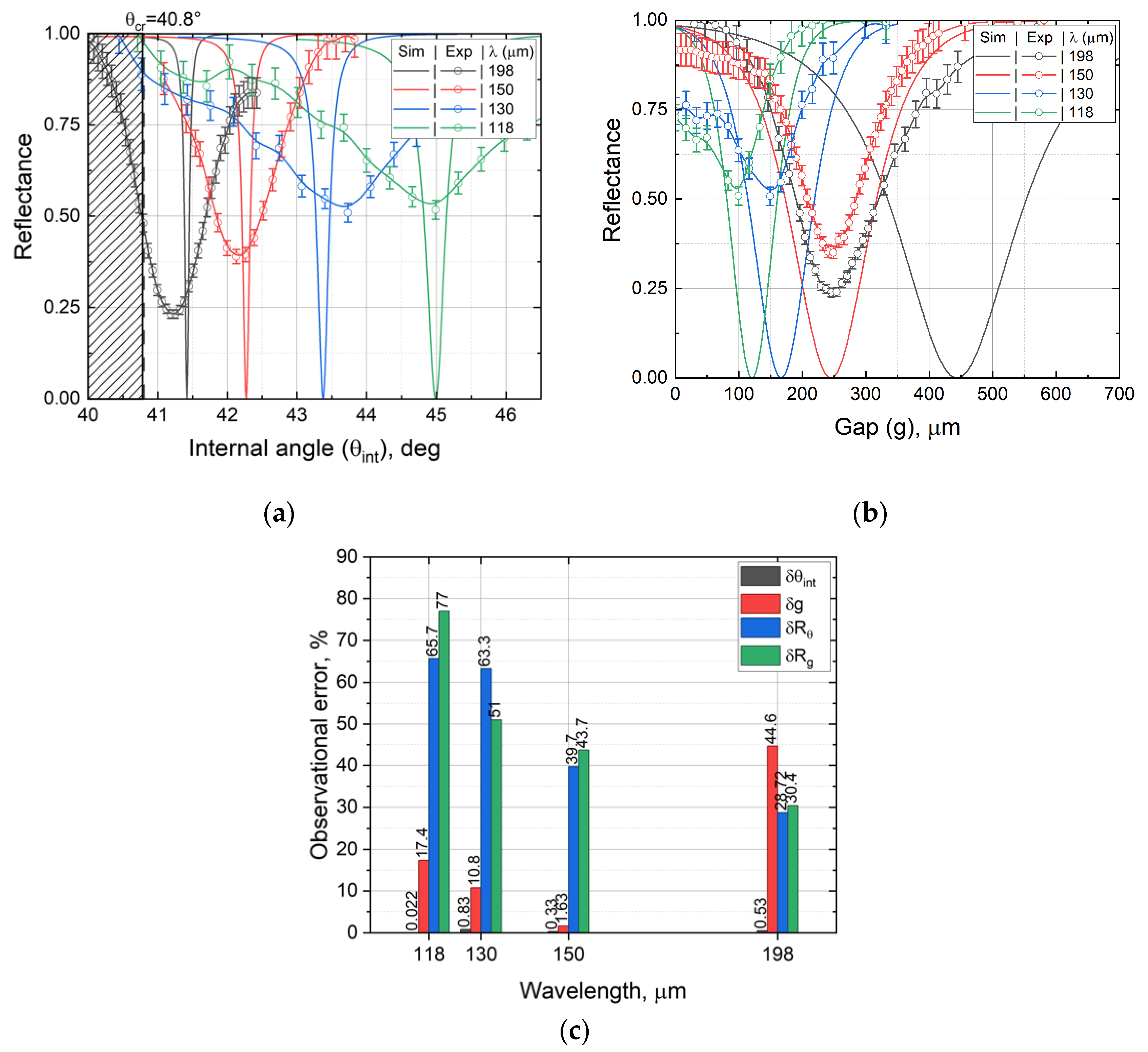
7.2. Angular and Gap Spectra

The angular spectra are shown in Figure 9a. It is immediately clear that the experimental dip width was significantly larger than the simulated one, while the dip depth in the experiments was smaller than that in the simulation. For example, (see Section 6.2), the angular width is estimated at about 0.22° at 150 μm, while the experiment gives 1.2° at 150 μm, which is 5.5 times larger.
This shows that the spectral and angular widths of the incident beam have less impact on the experimental results than the broadening caused by absorption and diffraction due to the grating surface roughness, dispersion of the grating parameters, and the finite size of the grating. The assumption about the significant effect of the sources of the experimental angular broadening is confirmed by the increase in the depth and the decrease in the width of the dip with the growth of the radiation wavelength (see Figure 9a,b).
In addition to this, it can be noted that the experimental dip, corresponded to 198 μm (black line) slightly outside of the ATR regime. This is due to the higher losses in experiments and the relatively close proximity of the resonance to the critical angle. A similar effect is observed in the simulation results when the metal losses are increased (see Figure 7c).
The gap spectra are demonstrated in Figure 9b. The depth values in these spectra are almost similar to those we obtained in the angular spectra at the corresponding wavelengths (see δRθ and δRg in Figure 9c). The non-zero depth of the experimental resonance is attributed to the angular width of the beam and indicates that only a portion of the beam transforms into the SSPPs (see Section 6.2). The angular components of the beam that are not involved in the excitation process cannot be excluded from consideration, as the reflected beam is normalised with respect to the entire incident beam. The resonance depth can be increased, for example, by reducing the angular width of the incident beam. The dip width suffers less from the broadening effects than the angular spectra do, and their values are closer to the simulation results.

7.3. Optimal Incident Angle and Gap Distance
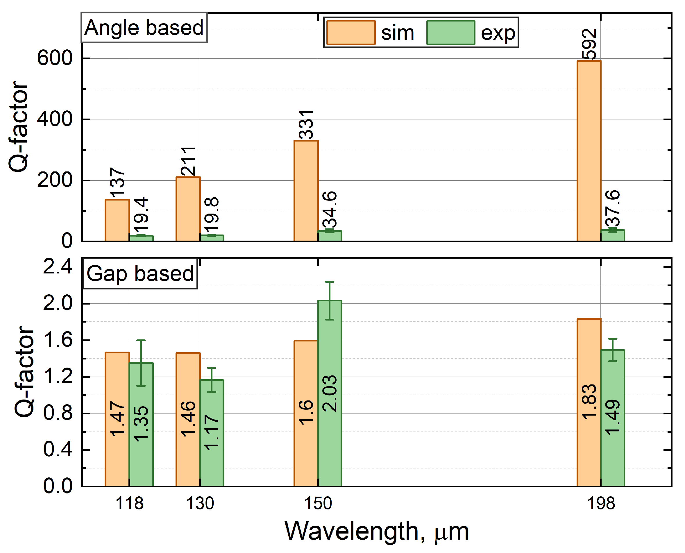
The optimal excitation angle and gap obtained experimentally and numerically are summarised in Table 1. In most cases, the experimental angles and gaps are close to the simulation ones. The observation error in the determination of the angular position of the resonance δθint does not exceed 1%, while the experimental gap position δg coincides with the simulation one with an accuracy of less than 17.4% (see Figure 9c).
As discussed earlier, the optimal angle is primarily determined by the phase matching conditions and its position can be affected by variation in structural parameters and the system misalignment. This explains the relatively low angular error observed in the experiment. In contrast, the optimal gap distance is governed by a combination of internal and radiation losses, which depend on various interrelated factors such as roughness of the surface, plasmon localisation, metal absorption, boundary effects due to the finite size of the grating, and even zero gap position errors. As a result, a relatively large deviation in the gap is acceptable. In absolute values, the gap error is less than 21 μm.
There exists only one large shift from the value predicted by the simulation, observed in several experimental series at a wavelength of 198 μm. In this case, the measured gap distance was nearly half that predicted by the simulation. This shift is related to the fact that, at this frequency, the resonance lies close to the light line, indicating strong coupling between the SSPP and the incident wave. Due to weak localisation, the scattering of THz SSPPs on the roughness occurs more intensely [48], which leads to the interference of waves in the gap with diffracted ones, resulting in the non-uniformity of the FEL beam intensity profile at the surface plasmon resonance (see Figure 8). As a result, the optimal coupling gap distance shifted to the lower values in the experiment. This effect can be replicated in the simulation by introducing additional losses into the system. For example, a similar critical coupling condition is observed in the simulation when X=85, as shown in Figure 7a.
Despite the fact that we used only a discrete number of frequencies in the experiment, the results indicate that we can continuously switch the resonant frequency in at least the 1-THz range from 1.51 to 2.54 THz and theoretically can increase the value up to 1.67 THz using a single grating. The obtained frequency tuning is significant compared to the other strategy of resonance switching. For instance, the active tunable metamaterials allow only achieving about 3–5% of frequency tuning from the initial position of resonance, which is typically less than 0.3 THz [49,50]. Table 2 summarises the typical spectral tunable ranges observed experimentally for both active and angle-dependent terahertz metamaterials.

7.4. Quality Factor

The Q factor for the gap and angular resonances can be defined as Q g = g o p t g and Q θ = θ o p t θ , correspondingly, where g o p t and θ o p t are the optimal gap and angular resonance positions, and g and θ are the full widths at half maximum of the resonances. Due to the broadening and position errors described in the previous sections, Q g in the experiments turned out to be of the same order as in the simulation, while the experimental Q θ was one order of magnitude smaller than the simulation one, as shown in Figure 10. The Q factor of the resonances in the angular spectra was within the range of 19.4–37.6, while the resonances of the gap spectra had the Q factor lying within the 1.17–2.03 range. Both the gap and angular quality factors grew with an increase in the resonance wavelength and achieved their maximum values at a wavelength of 198 μm. As mentioned in the previous section, this wavelength dependency is clear because of the growing effects of the gap dispersion, absorption, and diffraction on the propagation of the spoof surface plasmon waves along the grating at smaller wavelengths. The maximum angular quality factor Q θ = 37.6 ± 6.7   a t   1.51   T H z 198   μ m is comparable to a value of 43.3 at 0.738 THz, which was obtained with frequency spectrum and phase measurements by Huang [24], but is lower than a Q factor of 170 at 1.71 THz, obtained by the similar phase method by Binghao Ng [14].

8. Discussion

The experimental excitation of spoof surface plasmons on a 1D subwavelength grating in the attenuated total reflection scheme is a new topic. The first experimental demonstration was carried out in 2013 by Binghao Ng [14], repeated in 2019–2020 by Huang [23,24]. Moreover, they showed the sensor capabilities of this type of metamaterial using various liquids. The authors were not limited to that and demonstrated the possibility of improving the quality of resonances through phase measurements and coupling gap variation. Although all these measurements were conducted using a time domain spectrometer, and the grating responses were recorded over a wide frequency range, the work was performed in one frequency resonance regime. The authors did not study, for example, the analyte–grating interaction at various frequencies and were not able to unleash the full potential of the TDS and this metamaterial.
Compared to the above works, we operated in the frequency domain and realised the attenuated total reflection technique with angular interrogation to collect data at various frequencies and angles. This allowed us to change the resonance of the subwavelength grating in the dispersion curve through variation of the incidence angle and variation and implement passive tuning of the resonance. We were not able to collect phase information, which would significantly improve the resonance quality and enable work with highly absorbent substances. However, as shown in our article, the angular spectra with a tunable quasi-monochromatic source of radiation might be a good alternative, without the necessity of using a complicated TDS technique, which has various experimental limitations and uncertainties. It is especially promising in connection with the development of compact frequency-tunable THz radiation sources, such as quantum cascade lasers and frequency multipliers based on avalanche diodes [56].
Moreover, like other authors, we presented gap variation to enable modulation of the coupling efficiency. It is highly important for the adjustment of the field enhancement when the refractive index of the surrounding medium changes or during layer scanning, for instance. Another difference is that we recorded our data with a matrix detector. This new feature of our setup opens up new ways to analyse local interactions of SSPPs with the surrounding media.
Although our experimental results are in good agreement with the theory, the capability of our setup is still limited. (1) We still cannot provide precise control of the zero gap distance. (2) The limited prism size and the large beam diameter do not allow us to tune the full available frequency region across the entire dispersion curve and reduce the diffracted components of the incident beam that do not contribute to the formation of the spoof plasmon resonance. (3) The system of phase measurements has not been implemented yet. We will continue developing the setup to improve the quality of the resonances and expand its potential applications.
The attenuated total reflection scheme in the Otto configuration combined with the subwavelength grating can become a platform for the terahertz real-time enhanced spectroscopy and imaging since it provides full control over spoof plasmon resonances. However, the interaction of spoof plasmon resonances with liquid analytes is unclear, and the problem of calibration of resonances over a wide frequency range to extract parameters of the analyte has not been solved. In addition, excitation and analysis of higher SSPP modes have not been realised experimentally yet. All of these might be topics for further research.

9. Conclusions

We demonstrated excitation of the fundamental spoof surface plasmon mode on a 1D subwavelength rectangular profile grating in the terahertz frequency range. Using the attenuated total internal reflection technique with angular interrogation in the Otto configuration in the frequency domain, we successfully carried out experiments and measured spectra at different frequencies by tuning the resonance from 1.51 to 2.54 THz, which corresponds to 1-THz tunability, which cannot be achieved with active tunable metamaterials. The obtained Q factors of the angular resonances lie within the range of 19.4–37.6, reaching the maximum at a wavelength of 198 μm. These values are comparable to those other authors obtained earlier using similar structures. By changing the gap, we were able to control the efficiency of coupling of the prism evanescent wave and the spoof surface plasmon wave, which leads to modulation of the absorption characteristics. In addition, a new recording system realised in our in-house setup makes it possible to monitor the local response of the grating, which will enable real-time tracking of changes in the surrounding medium. An experimental realisation of all capabilities of this metamaterial at once was shown for the first time. All of this is highly important for enhanced terahertz real-time absorption spectroscopy and imaging, and the presented results bring us closer to the implementation of these techniques.

Author Contributions

This work was realised through the collaboration of all authors. O.K.: contributing to the main results, original draft preparation; V.G.: reviewing and editing; experimental investigation. B.G.: sample preparation, resources V.N.: sample preparation, resources. All authors have read and agreed to the published version of the manuscript.

Funding

This research received no external funding.

Data Availability Statement

The raw data supporting the conclusions of this article will be made available by the authors on request.

Acknowledgments

The work was carried out at the shared research facility Siberian Center for Synchrotron and Terahertz Radiation on the basis of the Novosibirsk Free Electron Laser at Budker Institute of Nuclear Physics SB RAS.

Conflicts of Interest

The authors declare no conflicts of interest.

Abbreviations

The following abbreviations are used in this manuscript:
SSPPspoof surface plasmon polariton
SPPsurface plasmon polaritons
THzterahertz
ATRattenuated total reflection
NovoFELNovosibirsk free electron laser

References

  1. Zayats, A.V.; Smolyaninov, I.I.; Maradudin, A.A. Nano-Optics of Surface Plasmon Polaritons. Phys. Rep. 2005, 408, 131–314. [Google Scholar] [CrossRef]
  2. Shalabney, A.; Abdulhalim, I. Sensitivity-enhancement Methods for Surface Plasmon Sensors. Laser Photonics Rev. 2011, 5, 571–606. [Google Scholar] [CrossRef]
  3. Maier, S.A. Plasmonics: Fundamentals and Applications; Springer: New York, NY, USA, 2007; ISBN 978-0-387-33150-8. [Google Scholar]
  4. Knyazev, B.A.; Kuzmin, A.V. Surface electromagnetic waves: From visible range to microwaves. Vestn. NGU Ser. Fiz. 2007, 2, 108–122. [Google Scholar] [CrossRef]
  5. Kukotenko, V.D.; Gerasimov, V.V.; Khasanov, I.S.; Lemzyakov, A.G.; Ivanov, A.I.; Antonova, I.V. Experimental Study of Terahertz Surface Wave Field on Metallic and Composite Graphene Films. In Proceedings of the 2024 IEEE 25th International Conference of Young Professionals in Electron Devices and Materials (EDM), Altai, Russian, 28 June–2 July 2024; pp. 1070–1073. [Google Scholar] [CrossRef]
  6. Gerasimov, V.V.; Knyazev, B.A.; Lemzyakov, A.G.; Nikitin, A.K.; Zhizhin, G.N. Growth of Terahertz Surface Plasmon Propagation Length Due to Thin-Layer Dielectric Coating. J. Opt. Soc. Am. B 2016, 33, 2196. [Google Scholar] [CrossRef]
  7. Gerasimov, V.V.; Nikitin, A.K.; Lemzyakov, A.G.; Azarov, I.A.; Kotelnikov, I.A. Obtaining the Effective Dielectric Permittivity of a Conducting Surface in the Terahertz Range via the Characteristics of Surface Plasmon Polaritons. Appl. Sci. 2023, 13, 7898. [Google Scholar] [CrossRef]
  8. Isaac, T.H.; Barnes, W.L.; Hendry, E. Determining the Terahertz Optical Properties of Subwavelength Films Using Semiconductor Surface Plasmons. Appl. Phys. Lett. 2008, 93, 241115. [Google Scholar] [CrossRef]
  9. Gerasimov, V.V.; Khasanov, I.S.; Kukotenko, V.D.; Lemzyakov, A.G.; Ivanov, A.I.; Antonova, I.V.; Cherevko, A.G. Terahertz Surface Plasmon Refractometry of Composite Graphene Nanoparticle Films. IEEE Trans. THZ Sci. Technol. 2025, 15, 61–68. [Google Scholar] [CrossRef]
  10. Rivas, J.G.; Kuttge, M.; Bolivar, P.H.; Kurz, H.; Sánchez-Gil, J.A. Propagation of Surface Plasmon Polaritons on Semiconductor Gratings. Phys. Rev. Lett. 2004, 93, 256804. [Google Scholar] [CrossRef]
  11. Gong, M.; Jeon, T.-I.; Grischkowsky, D. THz Surface Wave Collapse on Coated Metal Surfaces. Opt. Express 2009, 17, 17088. [Google Scholar] [CrossRef]
  12. Garcia-Vidal, F.J.; Fernández-Domínguez, A.I.; Martin-Moreno, L.; Zhang, H.C.; Tang, W.; Peng, R.; Cui, T.J. Spoof Surface Plasmon Photonics. Rev. Mod. Phys. 2022, 94, 025004. [Google Scholar] [CrossRef]
  13. Gao, Z.; Wu, L.; Gao, F.; Luo, Y.; Zhang, B. Spoof Plasmonics: From Metamaterial Concept to Topological Description. Adv. Mater. 2018, 30, 1706683. [Google Scholar] [CrossRef]
  14. Ng, B.; Wu, J.; Hanham, S.M.; Fernández-Domínguez, A.I.; Klein, N.; Liew, Y.F.; Breese, M.B.H.; Hong, M.; Maier, S.A. Spoof Plasmon Surfaces: A Novel Platform for THz Sensing. Adv. Opt. Mater. 2013, 1, 543–548. [Google Scholar] [CrossRef]
  15. Ng, B.; Hanham, S.M.; Wu, J.; Fernández-Domínguez, A.I.; Klein, N.; Liew, Y.F.; Breese, M.B.H.; Hong, M.; Maier, S.A. Broadband Terahertz Sensing on Spoof Plasmon Surfaces. ACS Photonics 2014, 1, 1059–1067. [Google Scholar] [CrossRef]
  16. Yao, H.; Zhong, S. High-Mode Spoof SPP of Periodic Metal Grooves for Ultra-Sensitive Terahertz Sensing. Opt. Express 2014, 22, 25149. [Google Scholar] [CrossRef] [PubMed]
  17. Yao, H.; Zhong, S.; Tu, W. Performance Analysis of Higher Mode Spoof Surface Plasmon Polariton for Terahertz Sensing. J. Appl. Phys. 2015, 117, 133104. [Google Scholar] [CrossRef]
  18. Zhang, Y.; Hong, Z.; Han, Z. Spoof Plasmon Resonance with 1D Periodic Grooves for Terahertz Refractive Index Sensing. Opt. Commun. 2015, 340, 102–106. [Google Scholar] [CrossRef]
  19. Chen, L.; Yin, H.; Chen, L.; Zhu, Y. Ultra-Sensitive Fluid Fill Height Sensing Based on Spoof Surface Plasmon Polaritons. J. Electromagn. Waves Appl. 2018, 32, 471–482. [Google Scholar] [CrossRef]
  20. Zhao, R.; Lu, G.; Yin, H.; Liang, J.; Zeng, D.; Xiao, H. Terahertz Sensor Study Based on Spoof Surface Plasmon Polaritons. Int. J. Antennas Propag. 2020, 2020, 2504626. [Google Scholar] [CrossRef]
  21. Chen, X.; Xiao, H.; Lu, G.; Zhao, R. Refractive Index Sensing Based on Terahertz Spoof Surface Plasmon Polariton Structure. J. Phys. Conf. Ser. 2020, 1617, 012008. [Google Scholar] [CrossRef]
  22. Yao, H.; Zhang, W.; Liu, W.; Mei, H. Resolved Terahertz Spectroscopy of Tiny Molecules Employing Tunable Spoof Plasmons in an Otto Prism Configuration. J. Opt. 2022, 24, 045301. [Google Scholar] [CrossRef]
  23. Huang, Y.; Zhong, S.; Shi, T.; Shen, Y.-C.; Cui, D. HR-Si Prism Coupled Tightly Confined Spoof Surface Plasmon Polaritons Mode for Terahertz Sensing. Opt. Express 2019, 27, 34067. [Google Scholar] [CrossRef] [PubMed]
  24. Huang, Y.; Zhong, S.; Shi, T.; Shen, Y.; Cui, D. Terahertz Plasmonic Phase-Jump Manipulator for Liquid Sensing. Nanophotonics 2020, 9, 3011–3021. [Google Scholar] [CrossRef]
  25. Huang, Y.; Singh, R.; Xie, L.; Ying, Y. Attenuated Total Reflection for Terahertz Modulation, Sensing, Spectroscopy and Imaging Applications: A Review. Appl. Sci. 2020, 10, 4688. [Google Scholar] [CrossRef]
  26. Kameshkov, O.E.; Gerasimov, V.V. Excitation of Terahertz Plasmonic Resonance on a Subwavelength Metallic Grating in an Attenuated Total Reflection Scheme Using a Monochromatic Radiation Source. J. Surf. Investig. 2023, 17, 1463–1471. [Google Scholar] [CrossRef]
  27. Garcia-Vidal, F.J.; Martín-Moreno, L.; Pendry, J.B. Surfaces with Holes in Them: New Plasmonic Metamaterials. J. Opt. A Pure Appl. Opt. 2005, 7, S97–S101. [Google Scholar] [CrossRef]
  28. Shen, L.; Chen, X.; Yang, T.-J. Terahertz Surface Plasmon Polaritons on Periodically Corrugated Metal Surfaces. Opt. Express 2008, 16, 3326. [Google Scholar] [CrossRef] [PubMed]
  29. Rusina, A.; Durach, M.; Stockman, M.I. Theory of Spoof Plasmons in Real Metals. Appl. Phys. A 2010, 100, 375–378. [Google Scholar] [CrossRef]
  30. Erementchouk, M.; Joy, S.R.; Mazumder, P. Electrodynamics of Spoof Plasmons in Periodically Corrugated Waveguides. Proc. R. Soc. A 2016, 472, 20160616. [Google Scholar] [CrossRef] [PubMed]
  31. Jiang, T.; Shen, L.; Zhang, X.; Ran, L.-X. High-order modes of spoof surface plasmon polaritons on periodically corrugated metal surfaces. PIER M 2009, 8, 91–102. [Google Scholar] [CrossRef]
  32. Bulgakova, V.V.; Gerasimov, V.V.; Goldenberg, B.G.; Lemzyakov, A.G.; Malkin, A.M. Study of Terahertz Spoof Surface Plasmons on Subwavelength Gratings with Dielectric Substance in Grooves. Procedia Eng. 2017, 201, 14–23. [Google Scholar] [CrossRef]
  33. Khasanov, I.S.; Gerasimov, V.V.; Kameshkov, O.E.; Nikitin, A.K.; Kassandrov, V.V. Observation of Surface Plasmon Resonance in Monochromatic Terahertz Radiation on Indium Antimonide. J. Surf. Investig. 2023, 17, 1052–1059. [Google Scholar] [CrossRef]
  34. Dominique, B.; Otto, A. Excitations of Surface Plasmon Polaritons by Attenuated Total Reflection, Revisited. Riv. Nuovo C. 2013, 36, 173–209. [Google Scholar] [CrossRef]
  35. Otto, A. Excitation of Nonradiative Surface Plasma Waves in Silver by the Method of Frustrated Total Reflection. Z. Phys. 1968, 216, 398–410. [Google Scholar] [CrossRef]
  36. Mason, D.R.; Menabde, S.G.; Park, N. Unusual Otto Excitation Dynamics and Enhanced Coupling of Light to TE Plasmons in Graphene. Opt. Express 2014, 22, 847. [Google Scholar] [CrossRef]
  37. Yeatman, E.M. Resolution and Sensitivity in Surface Plasmon Microscopy and Sensing. Biosens. Bioelectron. 1996, 11, 635–649. [Google Scholar] [CrossRef]
  38. RF Module User’s Guide, version 6.0, COMSOL, Inc. Available online: https://doc.comsol.com/6.0/doc/com.comsol.help.rf/RFModuleUsersGuide.pdf (accessed on 13 June 2025).
  39. Ordal, M.A.; Bell, R.J.; Alexander, R.W.; Long, L.L.; Querry, M.R. Optical Properties of Fourteen Metals in the Infrared and Far Infrared: Al, Co, Cu, Au, Fe, Pb, Mo, Ni, Pd, Pt, Ag, Ti, V, and W. Appl. Opt. 1985, 24, 4493. [Google Scholar] [CrossRef]
  40. Reznikova, E.; Mohr, J.; Boerner, M.; Nazmov, V.; Jakobs, P.-J. Soft X-ray Lithography of High Aspect Ratio SU8 Submicron Structures. Microsyst. Technol. 2008, 14, 1683–1688. [Google Scholar] [CrossRef]
  41. Goldenberg, B.G.; Lemzyakov, A.G.; Zelinsky, A.G.; Nazmov, V.P.; Pindyurin, V.F. Multibeam X-ray Lithography to Form Deep Regular Microstructures. J. Synch. Investig. 2016, 10, 92–95. [Google Scholar] [CrossRef]
  42. Siberian Center for Synchrotron and Terahertz Radiation on the Basis of the Novosibirsk Free Electron Laser at Budker Institute of Nuclear Physics SB RAS. Available online: https://ssrc.biouml.org (accessed on 24 March 2025).
  43. Goldenberg, B.G.; Lemzyakov, A.G.; Nazmov, V.P.; Pindyurin, V.F. Multifunctional X-ray Lithography Station at VEPP-3. Phys. Procedia 2016, 84, 205–212. [Google Scholar] [CrossRef]
  44. Shevchenko, O.A.; Vinokurov, N.A.; Arbuzov, V.S.; Chernov, K.N.; Davidyuk, I.V.; Deichuly, O.I.; Dementyev, E.N.; Dovzhenko, B.A.; Getmanov, Y.V.; Gorbachev, Y.I.; et al. The Novosibirsk Free-Electron Laser Facility. Bull. Russ. Acad. Sci. Phys. 2019, 83, 228–231. [Google Scholar] [CrossRef]
  45. Tydex. Available online: https://www.tydexoptics.com (accessed on 24 March 2024).
  46. Kubarev, V.V.; Kulipanov, G.N.; Kolobanov, E.I.; Matveenko, A.N.; Medvedev, L.E.; Ovchar, V.K.; Salikova, T.V.; Scheglov, M.A.; Serednyakov, S.S.; Vinokurov, N.A. Modulation Instability, Three Mode Regimes and Harmonic Generation at the Novosibirsk Terahertz Free Electron Laser. Nucl. Instrum. Methods Phys. Res. Sect. A Accel. Spectrometers Detect. Assoc. Equip. 2009, 603, 25–27. [Google Scholar] [CrossRef]
  47. Gerasimov, V.V.; Kameshkov, O.E.; Nikitin, A.K.; Khasanov, I.S.; Lemzyakov, A.G.; Antonova, I.V.; Ivanov, A.I.; Lien, N.T.H.; Nghia, N.T.; Anh, L.T.; et al. First Experimental Demonstration of the Wide-Field Amplitude Surface Plasmon Resonance Microscopy in the Terahertz Range. Photonics 2023, 10, 723. [Google Scholar] [CrossRef]
  48. Gerasimov, V.V.; Nikitin, A.K.; Vanda, V.S.; Lemzyakov, A.G.; Azarov, I.A. Dispersion of attenuation of surface plasmon polaritons on metal in the terahertz range. J. Infrared Millim. Terahz. Waves 2025, 46, 32. [Google Scholar] [CrossRef]
  49. Wang, L.; Wang, Y.; Zong, G.; Hu, W.; Lu, Y. Liquid Crystal Based Tunable Terahertz Metadevices. J. Mater. 2025, 11, 100888. [Google Scholar] [CrossRef]
  50. Li, J.; Chen, J.; Yan, D.; Fan, F.; Chen, K.; Zhong, K.; Wang, Y.; Tian, Z.; Xu, D. A Review: Active Tunable Terahertz Metamaterials. Adv. Photonics Res. 2024, 5, 2300351. [Google Scholar] [CrossRef]
  51. Tumashov, M.A.; Baena, J.D.; Del Risco, J.P.; Lazorskiy, P.A.; Glybovski, S.B.; Kuznetsov, S.A. Angle-Dependent Metasurface for Nonspectroscopic THz Sensing of Submicrometer Films. IEEE Sens. J. 2023, 23, 27262–27272. [Google Scholar] [CrossRef]
  52. Xie, Y.; Liu, X.; Zhou, J.; Zhang, H.; Lin, J.-Y.; Chen, W.; Zhu, L.-G.; Meng, K.; Liu, Q.H.; Zhu, J. Enhancing Trace Terahertz Fingerprint Sensing by the Lossy Silicon Metagrating with a Gold Mirror. IEEE Trans. Microw. Theory Tech. 2024, 72, 2368–2377. [Google Scholar] [CrossRef]
  53. Zhu, W.M.; Liu, A.Q.; Zhang, X.M.; Tsai, D.P.; Bourouina, T.; Teng, J.H.; Zhang, X.H.; Guo, H.C.; Tanoto, H.; Mei, T.; et al. Switchable Magnetic Metamaterials Using Micromachining Processes. Adv. Mater. 2011, 23, 1792–1796. [Google Scholar] [CrossRef]
  54. Pitchappa, P.; Manjappa, M.; Krishnamoorthy, H.N.S.; Chang, Y.; Lee, C.; Singh, R. Bidirectional Reconfiguration and Thermal Tuning of Microcantilever Metamaterial Device Operating from 77 K to 400 K. Appl. Phys. Lett. 2017, 111, 261101. [Google Scholar] [CrossRef]
  55. Wang, L.; Ge, S.; Hu, W.; Nakajima, M.; Lu, Y. Graphene-Assisted High-Efficiency Liquid Crystal Tunable Terahertz Metamaterial Absorber. Opt. Express 2017, 25, 23873. [Google Scholar] [CrossRef]
  56. Lewis, R.A. A Review of Terahertz Sources. J. Phys. D Appl. Phys. 2014, 47, 374001. [Google Scholar] [CrossRef]
Figure 1. (a) Attenuated total reflection scheme in Otto configuration; (b) Typical dispersion curve. X-axis is limited by Brillouin zone, while Y-axis is restricted by condition of grating period being twice as small as wavelength, which is necessary for considering grating as subwavelength one; (c) Typical reflectance spectrum.
Photonics 12 00651 g001
Figure 2. Numerical schemes for calculation of (a) eigenmodes, (b) reflection spectra, and (c) meshing around grating domain.
Photonics 12 00651 g002
Figure 3. Scheme of experimental setup with photo inserts of its part and subwavelength grating after magnetron sputtering.
Photonics 12 00651 g003
Figure 4. SSPP dispersion curve obtained with numerical simulation and analytical equation. Highlighted points with filled rectangles reflect positions of experimental resonances, while limiting points of our setup and grating are shown in rectangles without color.
Photonics 12 00651 g004
Figure 5. (a) Gap–angular map (λ = 150 μm) with inset of gap spectrum with optimal parameters of SPP coupling below it; (b) Frequency–angular map (g = 245 μm) with inset of angular spectrum with optimal parameters of SPP coupling below it.
Photonics 12 00651 g005
Figure 6. (a) Penetration depth of electric field above grating and (b) optimal coupling gap. Values in coloured circles correspond to those in circles of similar colours in Figure 4.
Photonics 12 00651 g006
Figure 7. (a) Dependence of the optimal coupling gap on factor X at λ = 198 μm; (b) Gap reflectance spectra as a function of factor X at λ = 198 μm; (c) Angular reflectance spectra as a function of factor X at at λ = 198 μm.
Photonics 12 00651 g007
Figure 8. Reflected beam images for subwavelength grating with different gaps between prism and grating. Radiation wavelength λ = 130 μm (2.3 THz); internal angle of incidence θint = 43.7 degrees. White dotted line: region of averaging of reflected beam signal.
Photonics 12 00651 g008
Figure 9. Experimental results: (a) angular spectrum; (b) gap spectrum; (c) observation errors.
Photonics 12 00651 g009
Figure 10. Q factors obtained experimentally and numerically.
Photonics 12 00651 g010
Table 1. Optimal SSPP excitation incident angles (θint) and gap distances (gopt).
SimulationExperiment
Wavelength,
μm
Frequency, THzGap,
μm
Angle,
deg
Gap,
μm
Angle,
deg
198 ± 0.511.51 ± 0.008444 ± 0.541.42 ± 0.005245.8 ± 541.2 ± 0.1
150 ± 0.852 ± 0.01245 ± 0.542.27 ± 0.005249 ± 542.13 ± 0.1
130 ± 0.672.306 ± 0.012167 ± 0.543.37 ± 0.005149 ± 543.73 ± 0.1
118 ± 0.342.535 ± 0.013121 ± 0.544.99 ± 0.005100 ± 544.98 ± 0.1
Table 2. Typical tunable range of terahertz metamaterials.
ApproachSpectral Tuning Range, THzTunable Range, GHzReference
Angle-dependent metasurface0.139–0.149810.8[51]
Angle-dependent metagrating0.5–0.5550[52]
MEMS, thermal tuning0.32–0. 43110[53]
MEMS, mechanical tuning2.12–2.28160[54]
Liquid crystal, electrical tuning0.75–1250[55]
Metal grating with angular dispersion1.51–2.541030This work
Disclaimer/Publisher’s Note: The statements, opinions and data contained in all publications are solely those of the individual author(s) and contributor(s) and not of MDPI and/or the editor(s). MDPI and/or the editor(s) disclaim responsibility for any injury to people or property resulting from any ideas, methods, instructions or products referred to in the content.

