Article

Design and Optimization of Broadband Optical Half-Band Filters Based on Cascaded MZIs

The State Key Laboratory of Precision Manufacturing for Extreme Service Performance, The College of Mechanical and Electrical Engineering, Central South University, Changsha 410083, China
*
Author to whom correspondence should be addressed.
Photonics 2025, 12(6), 618; https://doi.org/10.3390/photonics12060618
Submission received: 11 May 2025 / Revised: 15 June 2025 / Accepted: 16 June 2025 / Published: 18 June 2025

Abstract

:
In optical communication systems, optical half-band filters are essential for efficient spectral separation, necessitating stringent performance criteria such as a wide spectral range, low insertion loss, and minimal crosstalk. This paper proposes a broadband optical half-band filter based on a cascaded Mach–Zehnder Interferometer (MZI) structure, which effectively improves spectral separation by enhancing flatness and sharpness at transition edges through the optimization of delay line length differences and phase compensation values. The results demonstrate that the proposed design achieves an insertion loss below 0.45 dB and inter-band crosstalk under −20.7 dB over a 40 nm bandwidth, with a roll-off of 2.2 dB/nm between 1517 nm and 1528 nm. The findings highlight the technical advantages of cascaded MZI structures in achieving high-precision spectral separation, offering a valuable reference for the development of future high-performance optical communication networks and integrated optical devices.

1. Introduction

Optical filters are critical components in modern optical communication networks [1,2], serving the essential functions of precise spectral separation and channel management. Optical half-band filters selectively divide the spectrum, ensuring high transmission in one band while effectively suppressing the other. Leveraging the unique advantage of spectral symmetry, such filters meet the demand for precise separation in modern optical communication systems. Characterized by high-precision spectral control and low insertion loss, these filters are widely applied in wavelength-division multiplexing (WDM) systems [3,4,5], optical signal processing [6,7], and optical network performance optimization [8,9]. However, achieving wide passband coverage, low insertion loss, and minimal crosstalk in narrow-gap spectral separation remains a major technical challenge.
The C-band is the most widely used operating wavelength range in optical communication, while the S-band offers potential for capacity expansion and distinct application value. This study focuses on the C-band (1528–1568 nm) and a subset of the S-band (1480–1517 nm). These two sub-bands are separated by only 11 nm, representing a typical scenario of narrow-gap spectral separation. Achieving sharp transition edges between the two bands in a broadband context while maintaining flat passbands remains a key challenge in optical half-band filter design. However, most existing filter designs focus on optimizing the spectral performance of broadband single-channel filters or narrowband multi-channel devices [10]. For example, integrated optical filters using adiabatic optimization of coupled waveguides have achieved significant progress in broadband operation, delivering a spectral range close to 100 nm with low insertion loss and flat passband characteristics [11]. Nevertheless, these designs face difficulties in balancing low insertion loss with sharpness at transition edges for multi-channel separation. Some studies have proposed innovative approaches to improve transition edge sharpness, such as filters based on silicon nitride and silicon oxynitride composite waveguides, which enhance dispersion contrast to achieve sharp transition edges across a wide spectral range [12]. However, these designs still face challenges in achieving precise adjacent band separation, particularly in boundary control, while material properties often result in high fiber coupling losses and challenges in achieving low insertion loss. In contrast, cascaded MZI-based filters offer an effective solution for narrow-gap spectral separation, offering structural flexibility, design simplicity, and tunable performance [13,14]. Flat passbands, low insertion loss, and low crosstalk performance can be achieved by adjusting coupling angles and delay line parameters [15]. Existing studies have demonstrated that increasing the number of cascaded MZI stages significantly improves passband flatness and reduces crosstalk [16]. However, most existing designs employ only a few stages, limiting their ability to fully meet the high-performance demands of narrow-gap spectral separation.
This study proposes an optical half-band filter design based on a 13-stage cascaded MZI structure to address the demands for low insertion loss, low crosstalk, and wide passband coverage. By optimizing delay line length differences and phase compensation values, the spectral separation performance between the C-band (1528–1568 nm) and the S-band (1480–1517 nm) is significantly enhanced. Theoretical analysis and simulation validation were conducted using the transfer matrix method and the beam propagation method (BPM), systematically examining how key parameters in the cascaded MZI design affect filter performance, including passband flatness, crosstalk suppression, and insertion loss control. The results demonstrate that the proposed design achieves excellent performance across a wide spectral range, providing a technical reference and practical guidance for the optimization of broadband optical filters.

2. Theoretical Model of Cascaded MZI

Figure 1 illustrates the schematic of the FIR half-band filter, composed of cascaded MZIs. The first coupler is a 3 dB coupler, and the delay line length difference for this first stage is ∆L. From the second stage onward, the delay line length difference is 2∆L. Each stage also includes a phase shift factor φk, with a value of π. Each directional coupler is characterized by a coupling angle θ, which determines the power splitting ratio, where the through port transmits cos2 θ and the cross port transmits sin2 θ [17]. The transfer function of the cascaded MZI can be expressed as follows [15]:
S ( z ) = G ( z ) j H * ( z ) z ( 2 N 1 ) j H ( z ) G * ( z ) z ( 2 N 1 )
where G(z) and H(z) represent the transfer functions of the through and coupling arms of the cascaded MZI, respectively, and G(z) is the para-Hermitian conjugate of G(z), defined as G(z) = G(1/z).
Equation (1) defines the signal transfer characteristics of the cascaded MZI, forming the theoretical basis for designing the maximally flat half-band filter. For the filter structure shown in Figure 1, its power expansion coefficients are given as follows [15]:
A 2 k 1 = 1 k + N i = 1 2 N ( N + 0.5 i ) 2 ( N k ) ! N 1 + k ! ( 0.5 k )
where k = 1, 2, …, N, and N is the number of cascaded MZIs (N ≥ 2).
According to Ref. [15], the filter design requires that G(z)G(z) satisfy the following:
G ( z ) G * ( z ) = 1 2 + k = 1 N A 2 k 1 z ( 2 k 1 ) + k = 1 N A ( 2 k 1 ) z 2 k 1
By solving G(z)G(z) = 0, a total of 4N−2 solutions are obtained. These zeros appear in reciprocal conjugate pairs. That is, if α 0 is a zero, then its corresponding reciprocal conjugate zero is 1 / α 0 * . During the selection process, only one zero from each reciprocal conjugate pair is retained ( α 0   α 1 α 2 N 1 ), while its reciprocal conjugate (e.g., 1 / α 0 * ) is excluded.
The transfer functions G(z) and H(z) can be calculated as follows:
G ( z ) = a 0 k = 1 2 N 1 ( 1 α k z 1 )
H ( z ) = a 0 k = 1 2 N 1 ( 1 + α k z 1 )
The coefficient a0 is determined by the following:
a 0 = 1 k = 1 2 N 1 ( 1 α k ) ( 1 α k * ) + k = 1 2 N 1 ( 1 + α k ) ( 1 + α k * )
After obtaining a0  α 0   α 1 α 2 N 1 , G(z) and H(z) can be fully determined. Subsequently, by extracting the coefficients of G(z) and H(z), the coupling angles from the first to the N-th stage can be determined using the decomposition algorithm described in the reference, with a phase shift factor of π for each stage [18]. This theoretical model supports the design of maximally flat half-band filters with an arbitrary number of stages and provides a theoretical foundation for optimizing the number of stages in such filters, as elaborated in Section 3.1.

3. Results and Discussion

As shown in Figure 2, the design aims to divide the 1480–1568 nm band into two parts: 1480–1517 nm (S-band) and 1528–1568 nm (C-band). After passing through the filter, the optical signal should achieve the performance requirements of a transmission loss below 0.9 dB and crosstalk below −12 dB. The crosstalk remains below −12 dB for both the separated 1480–1517 nm and 1528–1568 nm channels. Given the nearly equal lengths of the two bands, a design based on a maximally flat half-band filter effectively achieves this goal. The beam propagation method (BPM) is adopted for simulation, with a silica cladding and a silica waveguide core featuring a relative refractive index difference of 1.5%. To ensure single-mode transmission, the waveguide width and thickness are both set to 4.5 μm, with a simulation wavelength range of 1480–1568 nm.

3.1. Number of Stages in Cascaded MZIs

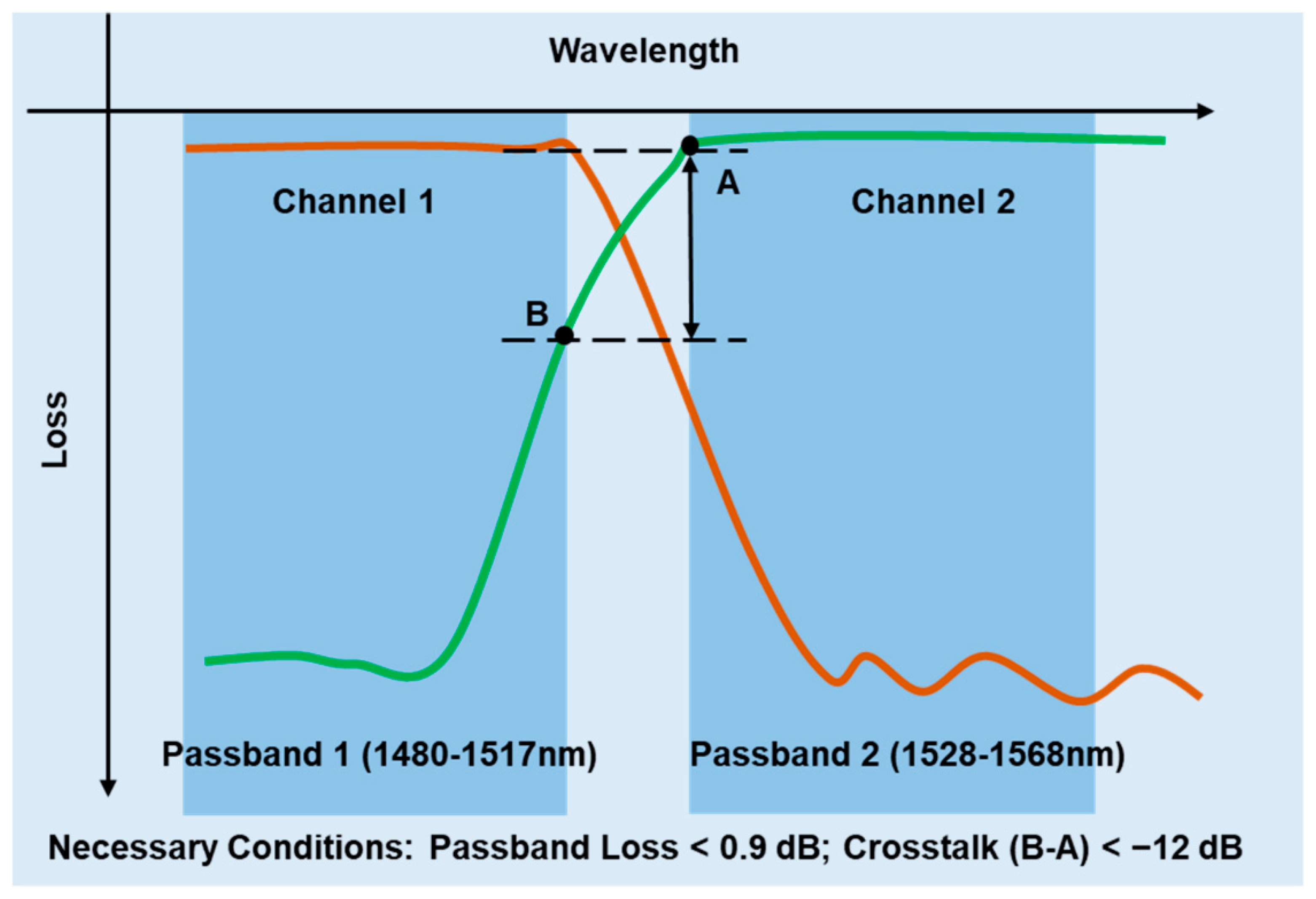
The channel spacing between the two filter channels is ∆λ = 51 nm, and the central wavelength of the filter is λ0 = 1522.5 nm. The refractive index of the cladding and the core is 1.444 and 1.474, respectively. The relationship between the path length difference (∆L) of the delay line in the first stage of the cascaded MZI, the channel spacing, and the central wavelength is given as follows:
Δ L = λ 0 2 2 n eff Δ λ
where neff is the effective refractive index of the waveguide at the central wavelength, with a value of 1.457. It should be noted that when the dispersion effect is weak, the effective refractive index (neff) can be used as an approximation of the group index (ng) to simplify the calculation [19].
Calculation with Equation (7) yields ∆
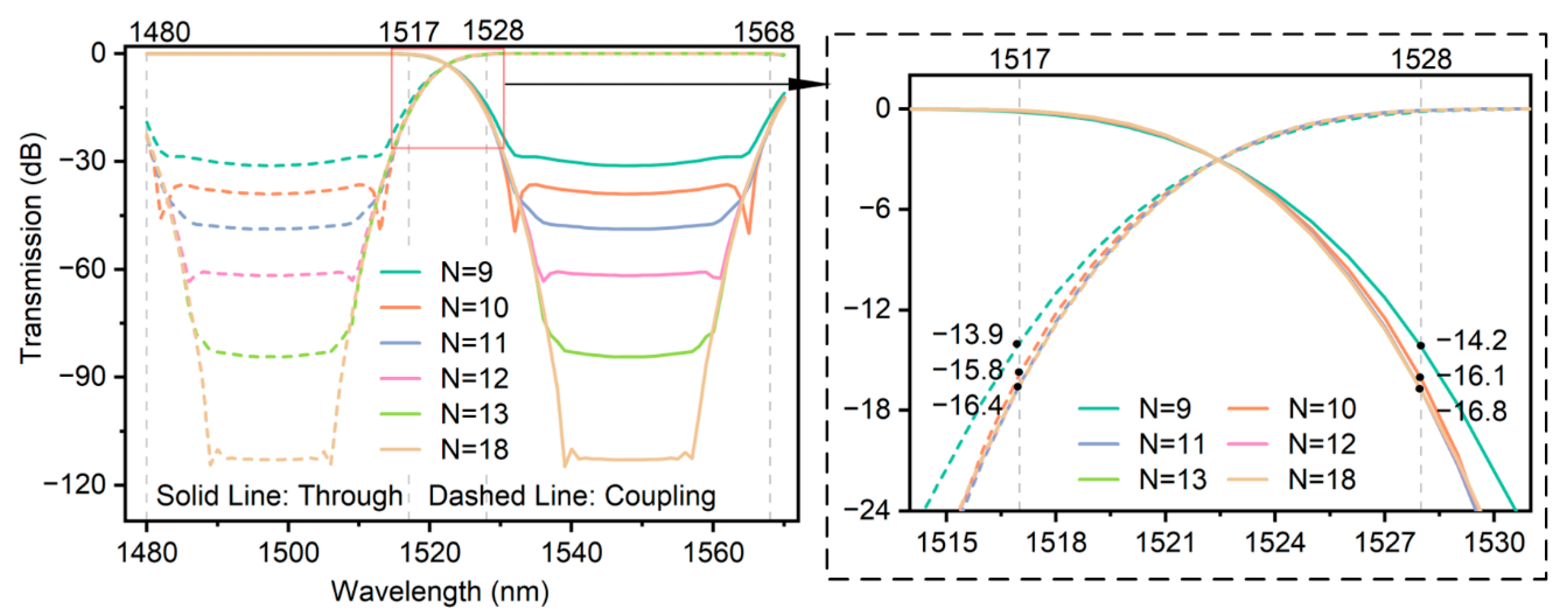
L = 15.60 μm as an initial estimate, while the transfer matrix calculation provides a more accurate result of 15.41 μm. This refinement accounts for the approximation error introduced by using the central wavelength in Equation (7). As the number of stages increases, both bands exhibit enhanced flatness within their passband ranges. Theoretical analysis indicates that the cascaded MZI satisfies the design requirements when the number of stages exceeds 11. Considering the inherent transmission loss in cascaded MZIs, it is essential to incorporate a design margin to compensate for attenuation and ensure optimal performance. Verification confirms that with 18 stages, the worst crosstalk occurs at 1517 nm, reaching −16.3 dB (yellow line in Figure 3). In this case, the phase shift factor is π, rendering it wavelength-independent.
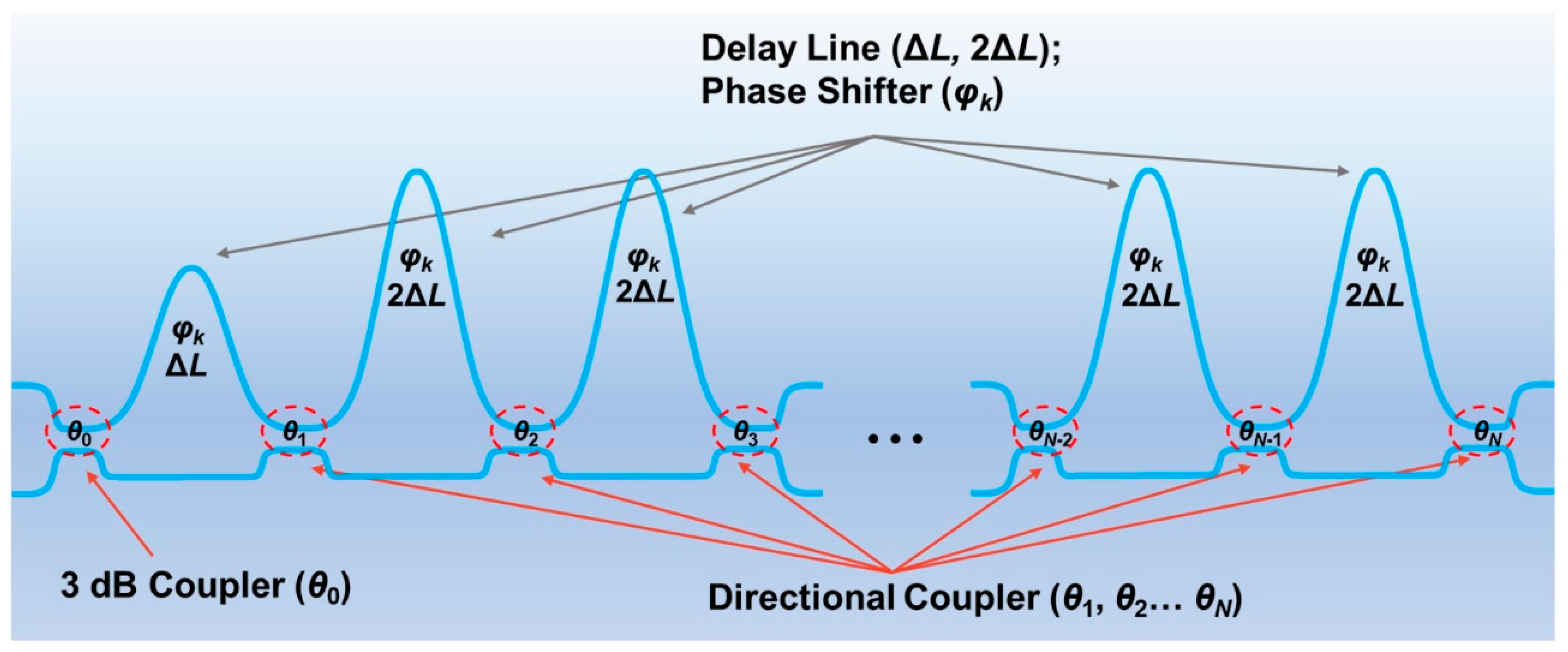
However, designing with the full 18-stage cascaded MZI presents several challenges. In such structures, an N-stage cascaded MZI contains (N+1) directional couplers. Table 1 lists the coupling angles and their corresponding cosine-squared and sine-squared values for the final (M+1)-th coupler within the first M stages of the full 18-stage cascaded MZI. In the first 9 stages of the full 18-stage cascaded MZI, the 10th directional coupler exhibits a coupling angle of 0.085 rad, corresponding to cos2 θ = 0.9928 and sin2 θ = 0.0072. In the first 12 stages, the 13th directional coupler exhibits a coupling angle of 0.0045 rad (cos2 θ = 0.9999, sin2 θ = 0.0001), making it impractical to design a coupler with such an extreme 1:0 power splitting ratio. In the maximally flat half-band filter model by Kaname Jinguji [15], the coupling angles decrease from the second stage onward, and the approach of zero angles in the final stages renders the design impractical. The analysis of the power spectra for the truncated structures (Figure 3) shows that crosstalk improves by 2 dB when increasing from the 9-stage to the 10-stage configuration, but only by 0.6 dB from the 10-stage to the 11-stage configuration. Moreover, beyond the 11-stage configuration, the crosstalk values at 1517 nm and 1528 nm converge, indicating diminishing performance gains. Therefore, increasing the number of stages does not effectively improve crosstalk performance and only increases device length. To meet the design requirements, the following three constraints are proposed: (1) The final coupling angle of the cascaded MZI should be no less than 0.02 rad; (2) To minimize layout size, the number of stages is limited to 13; (3) Crosstalk should be less than −16 dB to provide sufficient margin.
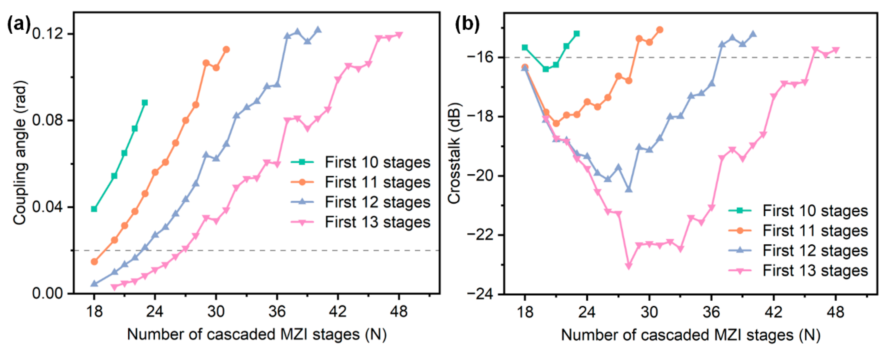
Based on these three aforementioned constraints, Figure 4 illustrates the design of cascaded MZIs that meet the requirements. In Figure 4, the horizontal axis represents the total number of stages N in the full cascaded MZI, while the vertical axis in Figure 4a indicates the coupling angle of the final directional coupler in the first M stages (M = 10, 11, 12, 13). It can be observed that as the total number of stages (N) increases, the corresponding final coupling angle in the truncated structure also increases. Meanwhile, Figure 4b shows that crosstalk initially improves but eventually worsens as N grows. If only Condition 1 (coupling angle > 0.02 rad) is considered, all cascaded MZIs above the dashed line in Figure 4a meet the requirement. Similarly, if only Condition 2 (crosstalk < −16 dB) is considered, all cascaded MZIs below the dashed line in Figure 4b meet the requirement. However, if both conditions must be satisfied simultaneously, then for a truncated 10-stage cascaded MZI to meet the requirements, it must be derived from a full 21- or 22-stage design; other stage numbers do not satisfy both constraints. Under the constraints of Condition 1 and Condition 2, while increasing the number of stages gradually enhances crosstalk performance, it also leads to a significant increase in device size, necessitating a trade-off between performance and size.
To clearly present the impact of directional couplers on filter performance, a summary of their structural characteristics is provided as follows. First, the coupling angles of the directional couplers vary across stages, as determined by the theoretical model of the maximally flat half-band filter [15]. In a complete cascaded MZI structure, the first coupler is a 3 dB directional coupler, while the coupling angles of subsequent couplers generally decrease stage by stage. As the number of stages increases, the total number of directional couplers also increases, leading to improved passband flatness and enhanced control over the transition band. However, it should be noted that the later-stage coupling angles may approach zero, significantly increasing the design and fabrication complexity of the couplers. Therefore, the filter design must strike a balance between performance optimization and fabrication feasibility.
The first 11 stages of the full 28-stage cascaded MZI have met the design requirements for the minimum coupling angle and crosstalk, while the crosstalk of the first 13 stages is further reduced to approximately −23 dB. This paper focuses on analyzing the performance of the first 13 stages of the full 28-stage cascaded MZI in Section 3.2 and compares the BPM simulation results with the theoretical lossless transmission. It should be noted that the maximally flat half-band filter design model proposed by Kaname Jinguji has certain limitations. Specifically, when the total number of stages N is 14–17 or 19, the crosstalk is approximately −4 dB, which fails to meet the design requirements. Since these issues are beyond the scope of this study, they are not analyzed further in this paper.

3.2. Optimization of Broadband Optical Half-Band Filters

In a cascaded MZI, the coupling ratio of directional couplers varies significantly with wavelength. By replacing directional couplers with an MZI structure and introducing delay lines at both ends, a wavelength-independent coupler (WIC) can be realized, enabling stable coupling ratios over a broadband range while maintaining a 90° output phase difference [4,20], as shown in Figure 5a. In the design of the WIC, the phase compensation values required to maintain a constant 90° output phase difference vary across different wavelengths. When the phase shift introduced by the delay lines equals an integer multiple of 2π, it does not affect the overall phase. Therefore, by comparing the phase deviation variances under different integer-multiple conditions, the group with the minimum variance is selected, and its average value is used as the phase compensation to ensure phase stability across the broadband range.
Figure 5b shows the phase compensation values versus wavelength for the first WIC in the 13-stage cascaded MZI within the minimum variance group. The wavelength range spans from 1480 nm to 1568 nm, with a sampling interval of 4 nm, resulting in 23 sampling points. It can be observed that different wavelengths require different compensation values to maintain the 90° output phase difference. In this case, the average compensation value is 4.18 μm, and the minimum variance is 9.75 × 10⁻⁵. Figure 5c further illustrates the phase compensation characteristics of the adjacent groups. The lower-adjacent group yields an average compensation of 3.13 μm with a variance of 7.78 × 10⁻⁴, while the upper-adjacent group has an average compensation of 5.23 μm with a variance of 1.39 × 10⁻⁴. Since the 13-stage cascaded MZI contains 14 directional couplers, there are 14 WICs that require phase compensation design.
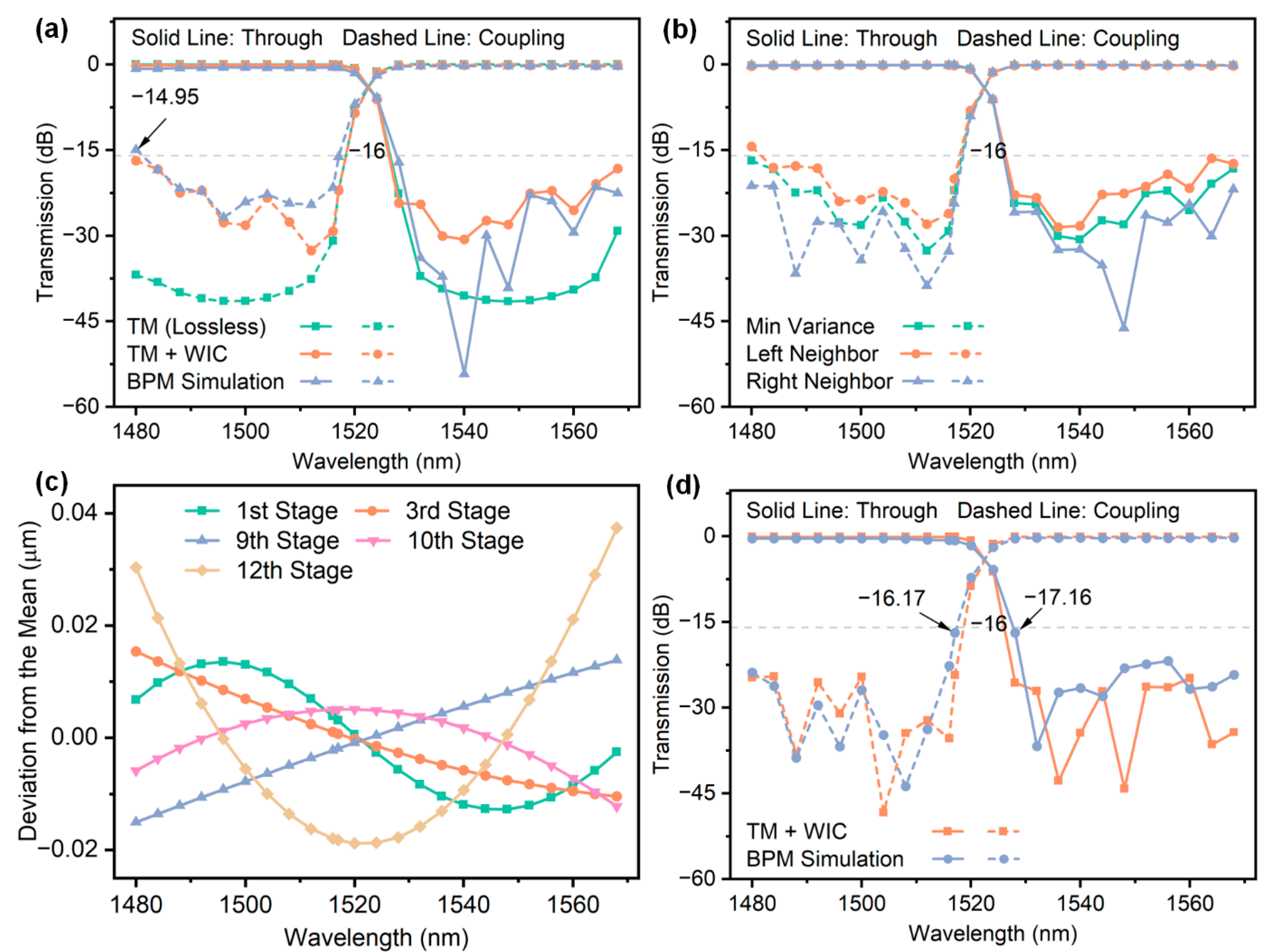
Figure 6a provides a detailed comparison of the spectral characteristics of the 13-stage cascaded MZI under three conditions: the transfer matrix (TM) method for lossless transmission, the TM method with WIC, and BPM simulation. The green line represents the theoretical spectrum under lossless transmission. Since the coupling ratio of the directional couplers does not vary with wavelength, it achieves the best crosstalk performance. The orange line corresponds to the TM method calculated spectrum with the directional couplers replaced by WIC. Due to the inability of the WIC to maintain constant coupling ratios and phase differences across the entire wavelength range, the crosstalk within the passband exceeds the theoretical value, while slightly above −16 dB at the edges. The blue line shows the spectrum obtained from BPM simulations. At the passband edge, the crosstalk further deteriorates to −14.95 dB at 1480 nm, failing to meet the design requirements. As shown in Figure 6b, the green line corresponds to the spectrum of the phase compensation value with the minimum variance, which does not yield the optimal spectral performance (all spectra are based on TM+WIC). Among the adjacent phase compensation values of the minimum variance group, the left-adjacent compensation value (orange line) results in slightly worse crosstalk performance, while the right-adjacent compensation value (blue line) achieves better crosstalk performance than the minimum variance group.
This phenomenon is primarily caused by the inherent limitations of using the average value as the delay line phase compensation. Figure 6c illustrates the difference between the actual phase compensation values of five WICs and their average value in a 13-stage cascaded MZI (note that phase compensation values can be converted to delay line length differences and vice versa). For instance, the green line represents the first WIC difference and exhibits sinusoidal variation with wavelength, while the orange line represents the third WIC difference that decreases monotonically with wavelength. For an individual WIC, the output phase difference is minimized and approaches 90° in the minimum variance group. However, in a cascaded MZI, variations in the differences between actual compensation values and their averages for each WIC across wavelengths cause the phase fluctuations of individual WICs to accumulate gradually, significantly impacting the overall output performance. As shown in Figure 6c, the average value is approximately centered within the 1480–1568 nm wavelength range, ensuring that the transmission spectrum at the central wavelength aligns more closely with the theoretical results. In contrast, at the band edges, random variations in the differences between actual compensation values and the average lead to the worst crosstalk performance. Therefore, even with the minimum variance group, the transmission spectrum may not achieve optimal performance.
In the 13-stage cascaded MZI, each stage exhibits a phase compensation value with minimum variance, accompanied by slightly higher variance values on either side. This results in a total of 313 possible compensation combinations, each generating a set of transmission spectra, from which the optimal combination can be identified by comparing crosstalk performance within the passband. However, with more than 1.5 million possible combinations, exhaustive calculations become too complex and impractical. To address this, a random sampling method is employed that selects a subset of combinations (e.g., 30,000, accounting for 2% of the total combinations) for optimization. Among these random samples, the crosstalk values of the transmission spectra calculated using the TM method reduced significantly from −16.7 dB to −24.3 dB (Figure 6d). Although the sampled combinations account for only 2% of all possible combinations, the optimized crosstalk performance approaches the theoretical lossless transmission level regardless of the limited sample size. Multiple sampling experiments indicate that the optimized crosstalk value stabilizes around −24 dB, validating the effectiveness of this method. In BPM simulations, the crosstalk at the passband edges is also significantly improved. However, at the two boundary wavelengths of 1517 nm and 1528 nm, the crosstalk remains unoptimized at around −16 dB and requires further investigation and optimization.
The first delay line length difference of the 13-stage cascaded MZI is ΔL = 15.41 μm; when the phase difference in the delay line undergoes a π-phase shift, the output spectrum remains unchanged. Specifically, when the delay line length difference changes by ΔLmean = λ0/Neff = 0.52 μm, the waveforms of the through arm and coupling arm are interchanged. As shown in
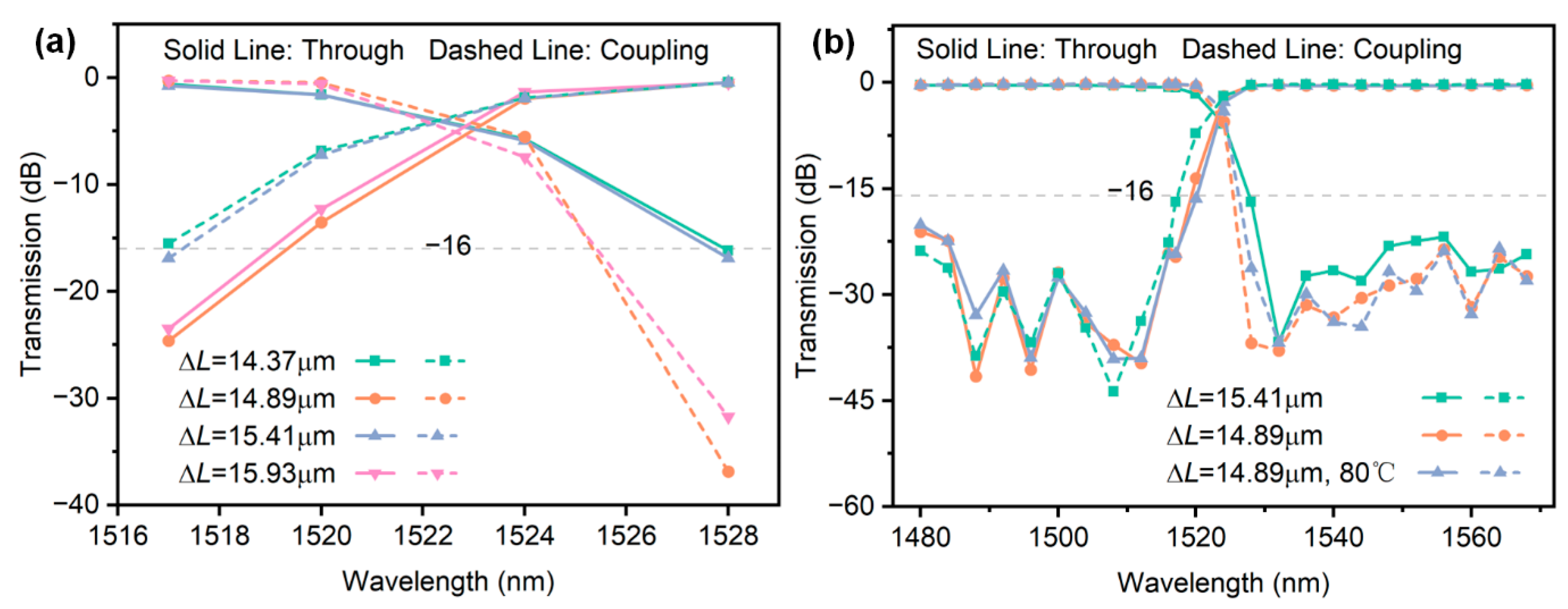
 Figure 7a, when ΔL decreases from 15.41 μm to 14.89 μm, the entire transmission spectrum shifts toward shorter wavelengths (blue shift), improving crosstalk at 1517 nm and 1528 nm. Further reducing ΔL to 14.37 μm causes the crosstalk at 1517 nm and 1528 nm to return to levels comparable to those at ΔL = 15.41 μm. On the other hand, increasing ΔL to 15.93 μm also improves the crosstalk at the passband edges. However, as the average value method for adjusting the delay line phase difference fails to induce a π-phase shift across all wavelengths, further reducing ΔL increases the channel spacing of the filter and worsens the crosstalk at 1517 nm and 1528 nm. Conversely, increasing ΔL decreases the channel spacing of the filter, which, in turn, degrades the crosstalk performance at 1480 nm and 1568 nm. Therefore, ΔL was adjusted from 15.41 μm to 14.89 μm, and BPM simulations were conducted. As shown in Figure 7b, the final crosstalk was optimized from −16.1 dB to −20.7 dB, while the insertion loss was reduced from 0.75 dB to 0.45 dB.
When using the TM method for calculations, changes in ΔL do not affect the crosstalk at the passband edges, whereas, for BPM simulations, variations reveal a significant impact of ΔL on the crosstalk in these regions. Moreover, this phenomenon is not confined to the first 13 stages of the full 28-stage cascaded MZI but is also observed across different numbers of cascaded stages. The most probable explanation is that the derivation of maximally flat half-band filters follows a frequency-division design approach. When mapped to the wavelength domain, this frequency division results in asymmetric bandwidths, especially over a broad wavelength range (1480–1568 nm). This non-uniform distribution in the wavelength domain causes the MZI filter to deviate from the theoretical “ideal flatness” during simulations, affecting the interference conditions of the cascaded MZI and leading to different phase compensation effects for various ΔL values [21]. BPM simulations account for the actual interference and dispersion effects of light wave propagation in waveguides, directly incorporating the cumulative errors of light waves in the wavelength domain. As a result, variations in ΔL have a more pronounced impact on simulations, while the TM method, relying on an idealized model, shows less sensitivity to ΔL changes and has minimal impact. In summary, BPM simulations performed with the ΔL = 14.89 μm configuration result in improved crosstalk performance and reduced insertion loss.
To evaluate the thermal stability of the proposed design, additional BPM simulations were performed under the configuration of ΔL = 14.89 μm by considering the thermo-optic effect of silica materials. According to the experimental results reported in [22,23], the thermo-optic coefficients of low-doped silica (used for the core layer) and pure fused silica (used for the cladding layer) are both approximately 1.0 × 10⁻⁵/°C at room temperature, with negligible difference between them. When the ambient temperature increases from 25 °C to 80 °C (a temperature difference of 55 °C), the refractive index increases by approximately 5.5 × 10⁻⁴. The refractive index of the waveguides was accordingly adjusted, and BPM simulations were recalculated. The simulation results are shown in Figure 6b. At 80 °C, the crosstalk of the 13-stage cascaded MZI slightly degrades from −20.7 dB to −19.7 dB, while the insertion loss remains almost unchanged at 0.45 dB. The filter still maintains acceptable performance under temperature fluctuations, demonstrating good thermal robustness. This further confirms that the cascaded MZI structure on the SiO2 platform exhibits excellent stability against temperature variations, making it particularly suitable for optical communication systems that do not require strict temperature control.
Table 2 presents the crosstalk comparison for cascaded MZIs with different stage numbers under various calculation methods. The table shows that when ΔL = 15.41 μm, only the BPM simulation results for the 13-stage cascaded MZI satisfy Condition 3 when ΔL = 15.41 μm. When ΔL = 14.89 μm, the BPM simulation results moved closer to the theoretical calculations, requiring only 12 stages to meet the condition. Under this configuration, the insertion loss is 0.43 dB, and the crosstalk is −18.8 dB. Additionally, with this configuration, the 13-stage cascaded MZI achieves a roll-off value of 2.2 dB/nm in the transition edge region between 1517 nm and 1528 nm, fully demonstrating the advantage of multi-stage cascaded MZIs in enhancing transition edge sharpness and effectively separating adjacent signals.
Although the primary focus of this study is the theoretical design and simulation analysis of the filter structure, practical engineering factors such as manufacturability, repeatability, and fabrication precision have been carefully considered throughout the design process.
First, the design is based on a SiO2 platform, which offers mature fabrication processes, reliable dimensional control, and low optical losses. This platform has been widely adopted in current photonic integration technologies and ensures high stability and process consistency. To enhance practical feasibility, the minimum coupling angle was limited to 0.02 rad. Extremely small coupling angles lead to power splitting ratios approaching 1:0, which are highly sensitive to fabrication deviations and thus difficult to realize with sufficient accuracy. This constraint improves the design’s robustness against process variations. In addition, to limit structural complexity and footprint, the maximum number of cascaded MZI stages was restricted to 13. This setting ensures adequate bandwidth and passband flatness while preventing excessive chip area and layout challenges. In future work, compact layout strategies such as ring-shaped configurations may be explored to further reduce the footprint.
Compared to other types of integrated optical filters—such as ring resonators [10], adiabatic couplers [11], and multimode interference gratings [24]—the cascaded MZI structure offers clearer design rules and greater flexibility in structural control. While it remains sensitive to fabrication accuracy, its adaptability and integration potential have been demonstrated in prior implementations on both Si [4] and SiO2 [25] platforms. Furthermore, the authors’ group has previously fabricated and tested various devices, such as Y-branch splitters, on the same SiO2 platform [26], providing valuable experience and a solid technical foundation for the future experimental validation of the proposed filter structure.
To further highlight the performance advantages of the proposed design, Table 3 summarizes a performance comparison with several recently reported optical filters based on different structures, considering key metrics such as insertion loss, crosstalk, guard band width, and 3 dB bandwidth of individual channels. Compared with other architectures, vernier microring resonators and multimode waveguide grating filters are generally limited by narrow 3 dB bandwidths, while adiabatically coupled waveguide filters exhibit relatively poor crosstalk suppression. AWG-based filters can support broadband operation but often involve trade-offs between passband width and guard band width. In contrast, the proposed maximally flat half-band filter simultaneously achieves a wide passband bandwidth (40 nm), narrow guard band width (11 nm), and strong crosstalk suppression (below −20 dB), offering a favorable balance among broadband capacity, channel isolation, and spectral utilization.
Future research offers several promising directions, such as the design of long-chain cascaded MZIs in a manufacturable ring-shaped layout, which presents a key challenge [25,28]. Such a layout can significantly reduce the device footprint, thereby improving wafer utilization. Additionally, future studies could focus on the optimization of non-half-band cascaded MZIs by flexibly adjusting the parameters of individual couplers and delay lines [29] to further improve filtering performance at boundary wavelengths. Lastly, for multi-channel filter designs, the hybrid integration of cascaded MZIs with other devices, such as arrayed waveguide gratings (AWGs) or micro-ring resonators [30], could be explored to achieve higher system integration and greater functional diversity.

4. Conclusions

This study designed and validated a broadband optical half-band filter based on a 13-stage cascaded Mach–Zehnder Interferometer (MZI), offering a solution for the efficient separation of the C-band (1528–1568 nm) and S-band (1480–1517 nm). By optimizing the delay line length difference and phase compensation values, the filter achieved excellent performance with an insertion loss of less than 0.45 dB and inter-channel crosstalk of less than −20.7 dB over a 40 nm bandwidth. The results demonstrate that increasing the number of cascaded MZI stages significantly enhances passband flatness and sharpness at transition edges. Moreover, optimizing phase compensation further reduces crosstalk at boundary wavelengths, achieving a roll-off value of 2.2 dB/nm at the transition edges. This study provides a new technical approach for the design and optimization of broadband optical half-band filters. However, the size optimization of long-chain cascaded MZIs remains a challenge for future research. Further investigations could aim to develop more efficient non-half-band cascaded MZI designs and highly integrated device layouts to address the demands of complex optical communication systems.

Author Contributions

Conceptualization, K.Z. and Y.Z.; data curation, K.Z. and Y.Z.; formal analysis, K.Z. and S.L.; funding acquisition, Y.Z.; investigation, X.T.; methodology, K.Z. and Y.Z.; project administration, Y.Z.; resources, Y.Z.; supervision, K.F.; validation, C.Y.; writing—original draft, K.Z.; writing—review and editing, K.Z., Y.Z. and X.O. All authors have read and agreed to the published version of the manuscript.

Funding

This work was supported in part by the National Key R&D Program of China (Grant No. 2024YFF0504900), the National Natural Science Foundation of China (Grant No. 52175445, U22A20200), and the Key Research and Development Program of Hunan Province, China (Grant No. 2023GK2024).

Institutional Review Board Statement

Not applicable.

Informed Consent Statement

Not applicable.

Data Availability Statement

Dataset available on request from the authors.

Conflicts of Interest

The authors declare that they have no known competing financial interests or personal relationships that could have appeared to influence the work reported in this paper.

References

  1. Liu, D.; Xu, H.; Tan, Y.; Shi, Y.; Dai, D. Silicon photonic filters. Microw. Opt. Technol. Lett. 2021, 63, 2252–2268. [Google Scholar] [CrossRef]
  2. Saha, N.; Brunetti, G.; di Toma, A.; Armenise, M.N.; Ciminelli, C. Silicon Photonic Filters: A Pathway from Basics to Applications. Adv. Photon. Res. 2024, 5, 2300343. [Google Scholar] [CrossRef]
  3. Ushida, J.; Murao, T.; Shiina, A.; Horikawa, T. Systematic identification of crosstalk and bandwidth upper limit in highly cascaded Mach–Zehnder lattice optical filters. Jpn. J. Appl. Phys. 2022, 61, 022001. [Google Scholar] [CrossRef]
  4. Papadovasilakis, M.; Chandran, S.; Gebregiorgis, Y.; Bian, Y.; Rakowski, M.; Aboketaf, A.; Augur, R.; Viegas, J. Fabrication-Tolerant O-Band WDM Filter With Phase-Balanced Tapered Arms and Wavelength-Independent Couplers. J. Lightw. Technol. 2024, 42, 258–267. [Google Scholar] [CrossRef]
  5. Ning, N.; Wang, X.; Yu, H.; Huang, Q.; Wang, Y.; Yang, J. Comparison of Silicon Lattice-Filter-Based O-Band 1×8 (De)Multiplexers With Flat and Gaussian-Like Passbands. IEEE Photonics J. 2022, 14, 1–5. [Google Scholar] [CrossRef]
  6. Fernández-Ruiz, M.R.; Carballar, A. Fiber Bragg Grating-Based Optical Signal Processing: Review and Survey. Appl. Sci. 2021, 11, 8189. [Google Scholar] [CrossRef]
  7. Samanta, S.; Dey, P.K.; Banerji, P.; Ganguly, P. Development of micro-ring resonator-based optical bandpass filter using SU-8 polymer and optical lithography. Opt. Mater. 2018, 77, 122–126. [Google Scholar] [CrossRef]
  8. Zhang, Y.; Huang, W.; Wang, X.; Xu, H.; Cai, Z. High-Extinction-Ratio Multipassband Filter With Flat-Top and Low-Dispersion. IEEE J. Quantum Electron. 2010, 46, 860–870. [Google Scholar] [CrossRef]
  9. Madsen, C.K. Subband all-pass filter architectures with applications to dispersion and dispersion-slope compensation and continuously variable delay lines. J. Lightw. Technol. 2003, 21, 2412–2420. [Google Scholar] [CrossRef]
  10. Morichetti, F.; Milanizadeh, M.; Petrini, M.; Zanetto, F.; Ferrari, G.; de Aguiar, D.O.; Guglielmi, E.; Sampietro, M.; Melloni, A. Polarization-transparent silicon photonic add-drop multiplexer with wideband hitless tuneability. Nat. Commun. 2021, 12, 4324. [Google Scholar] [CrossRef]
  11. Gorgulu, K.; Magden, E.S. Ultra-Broadband Integrated Optical Filters Based on Adiabatic Optimization of Coupled Waveguides. J. Lightw. Technol. 2023, 41, 5067–5077. [Google Scholar] [CrossRef]
  12. Ma, X.; Shao, Q.; Gu, J.; Lang, T.; Guo, X.; He, J.-J. Integrated Broadband Filter with Sharp Transition Edges Based on SiN and SiON Composite Waveguide Coupler. Photonics 2023, 10, 1285. [Google Scholar] [CrossRef]
  13. Prakash, P.; Ganesh Madhan, M. An Approach to Improve the Performance of FIR Optical Delay Line Filters. Lect. Notes Electr. Eng. 2016, 372, 35–42. [Google Scholar]
  14. Liu, L.; Zhang, L.; Chen, C.; Li, X.; Qiu, Y.; Zhao, P.; Hu, C.; Duan, J. Programmable Optical Filter Combining a FIR Structure and Intelligent Algorithms. IEEE Photonics Technol. Lett. 2024, 36, 1169–1172. [Google Scholar] [CrossRef]
  15. Jinguji, K.; Oguma, M. Optical half-band filters. J. Lightw. Technol. 2000, 18, 252–259. [Google Scholar] [CrossRef]
  16. Horst, F.; Green, W.M.J.; Assefa, S.; Shank, S.M.; Vlasov, Y.A.; Offrein, B.J. Cascaded Mach-Zehnder wavelength filters in silicon photonics for low loss and flat pass-band WDM (de-)multiplexing. Opt. Express 2013, 21, 11652–11658. [Google Scholar] [CrossRef]
  17. Madsen, C.K.; Zhao, J.H. Optical Filter Design and Analysis: A Signal Processing Approach; Wiley: New York, NY, USA, 1999; pp. 126–129. [Google Scholar]
  18. Jinguji, K.; Kawachi, M. Synthesis of coherent two-port lattice-form optical delay-line circuit. J. Lightw. Technol. 1995, 13, 73–82. [Google Scholar] [CrossRef]
  19. Hida, Y.; Jinguji, K.; Takato, N. Wavelength demulti/multiplexers with non-sinusoidal filtering characteristics composed of point-symmetrically connected Mach-Zehnder interferometers. Electr. Commun. Jpn. 1998, 81, 19–28. [Google Scholar] [CrossRef]
  20. Papadovasilakis, M.; Chandran, S.; Gebregiorgis, Y.; Bian, Y.; Rakowski, M.; Krishnamurthy, S.; Aboketaf, A.; Augur, R.; Viegas, J. Fabrication tolerant and wavelength independent arbitrary power splitters on a monolithic silicon photonics platform. Opt. Express 2022, 30, 33780–33791. [Google Scholar] [CrossRef]
  21. Mizuno, T.; Kitoh, T.; Oguma, M.; Inoue, Y.; Shibata, T.; Takahashi, H. Mach–Zehnder interferometer with a uniform wavelength period. Opt. Lett. 2004, 29, 454–456. [Google Scholar] [CrossRef]
  22. Leviton, D.B.; Frey, B.J. Temperature-dependent absolute refractive index measurements of synthetic fused silica. In Optomechanical Technologies for Astronomy; SPIE: Bellingham, WA, USA, 2006; Volume 6273, pp. 800–810. [Google Scholar]
  23. Rego, G.M. Temperature Dependence of the Thermo-Optic Coefficient of GeO2-Doped Silica Glass Fiber. Sensors 2024, 24, 4857. [Google Scholar] [CrossRef] [PubMed]
  24. He, J.; Zhang, M.; Liu, D.; Xiang, Y.; Liu, H.; Zhu, M.; Guo, Z.; Pan, B.; Huang, Y.; Yu, Z.; et al. First Realization of a Three-Channel Lithium-Niobate Photonic Filter for 50G Passive Optical Networks. ACS Photonics 2023, 10, 3740–3747. [Google Scholar] [CrossRef]
  25. Bidnyk, S.; Yadav, K.; Balakrishnan, A. Synthesis of ultra-dense interferometric chains in planar lightwave circuits. Integr. Opt. Dev. Mater. Technol. XXVI 2022, 12004, 91–96. [Google Scholar]
  26. Wang, J.R.; Zheng, Y.; Zou, X.J.; Zhao, Y.B.; Liu, J.Z.; Jiang, X.; Duan, J.A. Design and optimization of non-uniform 1 × 5 PLC splitter using orthogonal experimental method. Opt. Laser Technol. 2024, 168, 109955. [Google Scholar] [CrossRef]
  27. Zou, J.; Sun, F.; Wang, C.; Zhang, M.; Wang, J.; Lang, T.; Wang, X.; Le, Z.; He, J.-J. Silicon-Based Arrayed waveguide gratings for WDM and spectroscopic analysis applications. Opt. Laser Technol. 2022, 147, 107656. [Google Scholar] [CrossRef]
  28. Bidnyk, S.; Yadav, K.; Balakrishnan, A. Systems-on-chip in monolithically integrated silica-on-silicon platform. Integr. Opt. Dev. Mater. Technol. XXVIII 2024, 12889, 38–40. [Google Scholar]
  29. Hong, M.S.; Kim, D.U.; Lim, M.G.; Choi, D.J.; Her, M.J.; Park, Y.J.; Jeong, Y.; Park, J.; Han, S.; Yu, K.; et al. Programmable MZI Based on Si Photonic MEMS Tunable Delay Line. In Proceedings of the Conference on Lasers and Electro-Optics/Pacific Rim, Sapporo, Japan, 31 August–5 September 2022; p. CThP8F_07. [Google Scholar]
  30. Van Wijk, A.C.; Doerr, C.R.; Akca, I.B. Custom Arrayed Waveguide Gratings with Improved Performance. Adv. Photon. Res. 2023, 4, 2300198. [Google Scholar] [CrossRef]
Figure 1. Schematic of the FIR half-band filter in a 2 × 2 configuration.
Photonics 12 00618 g001
Figure 2. Spectral separation characteristics of the filter.
Photonics 12 00618 g002
Figure 3. Lossless spectral characteristics of selected stages from the full 18-stage cascaded MZI structure.
Photonics 12 00618 g003
Figure 4. Performance of truncated M-stage structures (M = 10–13) extracted from full N-stage cascaded MZIs: (a) coupling angle of the final directional coupler; (b) corresponding crosstalk.
Photonics 12 00618 g004
Figure 5. (a) The schematic of a WIC structure with phase compensation [4]; (b) phase compensation values for the first WIC in the 13-stage cascaded MZI; (c) phase compensation values for the lower-adjacent and upper-adjacent groups of the minimum variance group.
Photonics 12 00618 g005
Figure 6. (a) Spectra of the 13-stage cascaded MZI under different calculation methods; (b) spectra of the minimum variance group and its adjacent compensation groups; (c) difference between compensation values and their calculated mean across wavelengths; (d) optimized spectra after random sampling method.
Photonics 12 00618 g006
Figure 7. (a) Spectra of the 13-stage cascaded MZI at different ΔL values within the 1517–1528 nm range; (b) spectra of the 13-stage cascaded MZI after ΔL adjustment.
Photonics 12 00618 g007
Table 1. Final coupling angles in the first M stages of the 18-stage cascaded MZI.
M-Stage Cascade MZI (from Full 18-Stage MZI)91011121318
Coupling angle of (M+1)-th coupler (θ)0.0850.0390.0150.00458.9 × 10−49.1 × 10⁻⁶
cos2 θ0.99280.99850.99980.999911
sin2 θ0.00720.00150.00020.000100
Table 2. Crosstalk comparison for different stages under different calculation methods (full 28-stage, unit: dB).
Different Calculation Methods11-Stage12-Stage13-Stage
TM Method (Lossless)−16.3−19.7−22.0
BPM Simulation (ΔL = 15.41 μm)−12.7−14.6−16.1
BPM Simulation (ΔL = 14.89 μm)−15.8−18.8−20.7
BPM Simulation (ΔL = 14.89 μm, 80 °C)−15.1−17.8−19.7
Table 3. Performance comparison of different optical filters with this work.
Filter TypeInsertion Loss (dB) Crosstalk (dB)Guard Band Width (nm) 3dB Bandwidth (nm)
Vernier Microring Resonator [10]1−16N/A~0.32
Adiabatic Coupled Waveguides [11]1.5−10.0N/A96.6
Multimode Waveguide Gratings [24]0.2−301016
AWG (CWDM) [27]3.2−261412
This Work0.44−20.711>40
Disclaimer/Publisher’s Note: The statements, opinions and data contained in all publications are solely those of the individual author(s) and contributor(s) and not of MDPI and/or the editor(s). MDPI and/or the editor(s) disclaim responsibility for any injury to people or property resulting from any ideas, methods, instructions or products referred to in the content.

