Article

High-Power 650 nm Dense Spectral Beam Combining System Based on a Compression Telescope and Imaging Module

1
School of Information Science and Engineering, Shandong University, Qingdao 266237, China
2
Laboratory of Solid State Optoelectronics Information Technology, Institute of Semiconductors, Chinese Academy of Sciences, Beijing 100083, China
3
Weifang Academy of Advanced Opto-Electronic Circuits, Weifang 261021, China
4
State Key Laboratory on Integrated Optoelectronics, Institute of Semiconductors, Chinese Academy of Sciences, Beijing 100083, China
5
Center of Materials Science and Optoelectronics Engineering, University of Chinese Academy of Sciences, Beijing 100049, China
*
Author to whom correspondence should be addressed.
Photonics 2025, 12(6), 605; https://doi.org/10.3390/photonics12060605
Submission received: 6 May 2025 / Revised: 11 June 2025 / Accepted: 11 June 2025 / Published: 12 June 2025

Abstract

:
In this thesis, a 650 nm dense spectral beam combining (DSBC) system based on a compression telescope module (CM) and an imaging module (IM) is proposed (CM&IM DSBC system). Based on twenty-two (22) 650 nm COS (Chip on Submount) single-emitters, the system successfully achieves the first high-power and non-crosstalk beam combining output in the visible red band, with a maximum beam output power of 29.984 W. Compared with the 650 nm traditional DSBC system we proposed last year, the system solves both the crosstalk problem due to its larger optical path and the beam combining power drop caused by the direct reduction in the optical path. The final output power and DSBC efficiency are improved by more than 53% and 10%, respectively. The final beam brightness is improved by nearly 30%. Compared to a COS single-emitter, the brightness increase is more than 22 times. This achievement provides a new idea for the subsequent experimental research and product development of higher-power visible red-light band DSBC systems that can be applied in the industrial field.

1. Introduction

The spectral beam combining structure originated from the pulsed dye laser of the Littman team at the Massachusetts Institute of Technology (MIT) in 1978 [1]. Twenty years later, the first dense spectral beam combining based on fibre lasers and laser bar was realised by the teams of Cook and Fan at MIT, respectively [2,3]. By 2025, dense spectral beam combining has undergone more than 20 years of development. In recent years, dense spectral beam combining systems have been increasingly researched, and the output power has even been able to reach the kilowatt level. From 2014 to 2017, TRUMF in Germany used the thin-film filter (TFF) to increase the CW output power of the 960 nm semiconductor laser bars from 350 W to more than 1 kW, with the final combined beam parameter product BPP at 8.7 mm·mrad and the combining beam spectral width stabilised at 43 nm [4,5,6]. In 2017, the China Academy of Engineering Physics (CAEP) successfully realised a 976 nm dense spectral beam combining system with a CW output power of about 579 W and a beam quality factor M2 of about 10.9 [7]. In 2018, TRUMF in Germany continued to integrate the dense spectral beam combining module and finally succeeded in developing an infrared combining product with an CW output power of more than 2.5 kW [8]. From 2020 to 2022, led by Sichuan University in China, individual spectral beam combining modules were stacked using fibre coupling and polarisation beam combining, ultimately succeeding in increasing the CW output power of 976 nm semiconductor lasers from the hundred-watt level to over 2 kW [9,10,11]. In 2022, the Institute of Semiconductors of the Chinese Academy of Sciences (CAS) succeeded in increasing the beam combining efficiency of 960 nm laser bar to more than 100% by DSBC, with the CW output power of 59.2 W and a beam parameter product, BPP, at 2.028 mm·mrad [12]. In the same year, Teradiode of the United States of America successfully achieved DSBC in the blue band with an output power of about 400 W for the application of annealing amorphous silicon [13]. In 2023, the Beijing University of Technology (BJUT) used a solid-state laser as a light source and successfully increased the pulse energy of the combined beam output to 170 mJ, with a pulse width of 118 μs and a total beam quality factor M2 of about 2.8 × 2.2 [14]. In recent years, researchers around the world have further broadened the research scope of DSBC. Experimental studies combining DSBC with coherent beam combining and experimental concepts of DSBC in the mid-infrared band using metasurface have been realised [15,16].
So far, the research on dense spectral beam combining has mainly focused on the infrared and near-infrared band of more than 800 nm, while there are fewer studies on DSBC for the visible red-light band. High-power DSBC in the visible red band can be applied to solid-state laser pumping [17] and industrial composite processing. Our group achieved the first dense spectral beam combining based on 650 nm COS semiconductor single-emitters last year [18]. However, due to the large crosstalk and unstable spectrum, the initial beam combining system is difficult to apply in the field of solid-state and fibre lasers using visible red light as the pumping source. Crosstalk is a common phenomenon in spectral beam combining, mainly due to the mutual oscillation of different emitters involved in the combining process. The crosstalk phenomenon is mainly manifested as the appearance of additional oscillation wave peaks on the combined spectrum, apart from the normal locked oscillation peaks. This phenomenon can affect the beam quality. Although directly reducing the optical path can substantially scale down the crosstalk, it will likewise lead to a significant reduction in the combined output power. Therefore, in this paper, we successfully built the first high-power visible red-light DSBC system based on a compression telescope and imaging module (CM & IM DSBC system) through software simulation and structural optimisation. The system successfully combines 22,650 nm single-emitters into one high-beam-quality laser beam, and achieves spectrally stable oscillations with almost no crosstalk. Compared with the previous experiment [18], this system solves both the crosstalk problem due to its larger optical path and the decrease in beam power due to its direct reduction in the optical path. The final output power and beam efficiency are improved by more than 53% and 10%, respectively. The final beam brightness of the combined beam is improved by nearly 30%. The design and construction of this experiment and the analysis of the results are described in detail below.

2. Theoretical Simulation and Experimental Setup

2.1. 650 nm COS Single-Emitter and Simulation of Crosstalk Model

The semiconductor laser used in this experiment is a quantum well (QW) 650 nm COS (Chip on Submount) semiconductor laser single-emitter developed by Weifang Academy of Advanced Opto-Electronic Circuits. The internal laser chip structure of this single-emitter adopts an asymmetric waveguide design, with an active region size of about 1 μm × 100 μm and a centre wavelength (λ0) of 650 nm. The main chip structure is shown in Figure 1a. As can be seen from the figure, the quantum well (QW) layer, P waveguide layer, P cladding layer, N cladding layer, and N waveguide layer of this chip are all made of AlGaInP. The P contact layer and N contact layer are all made of GaAs. The thickness of the quantum well (QW) is about 8 nm. The package of this single-emitter is in the form of the COS (Chip on Submount), where the P-side is face-down on the brass heatsink. The operating performance of the 650 nm COS single-emitter is shown in 
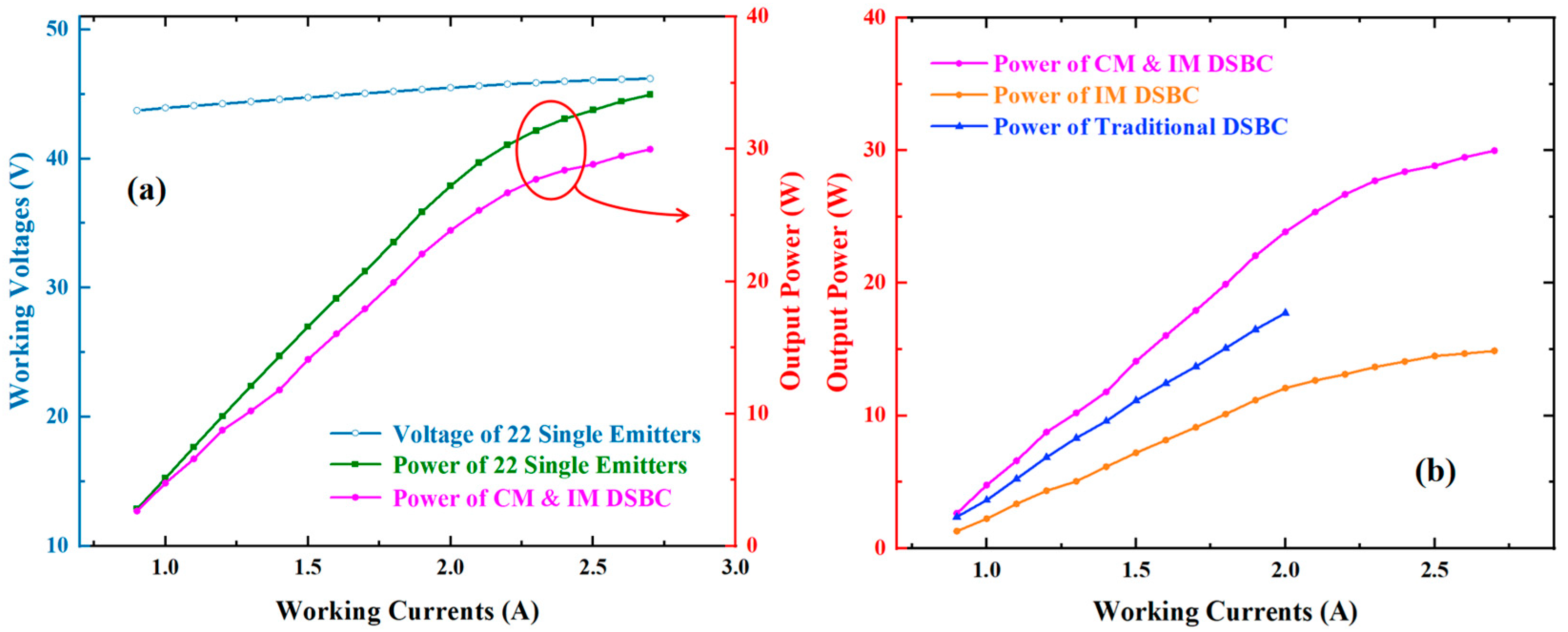
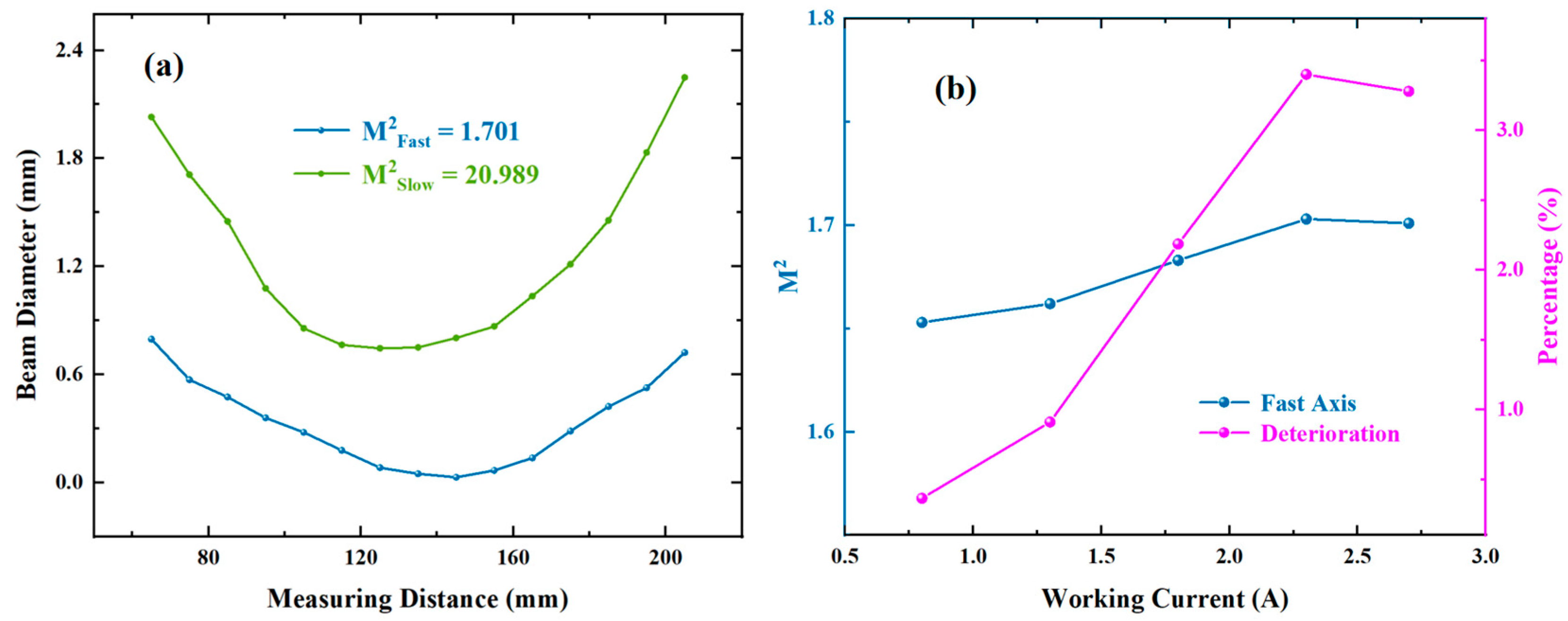
Figure 1b. The working voltage of this emitter is about 2 V, the threshold current is about 0.8 A, and the COD (Catastrophic Optical Damage) working current is 3.0 A. Therefore, the maximum current was set to 2.7 A in subsequent experiments. The output power of the single-emitter when the working current is controlled at 2.7 A is about 1.55 W. All the above data were measured at 25 °C in a water-cooled system, and the whole experiment was also conducted at this temperature. When the working current is 2.7 A, the divergence half-angles (the divergence angle at full-width at half-maximum) of the single-emitter in the fast-axis and slow-axis directions were 34.8° and 4.5°, respectively. The measured beam quality factors (M2) in the fast-axis and slow-axis directions, M2Fast and M
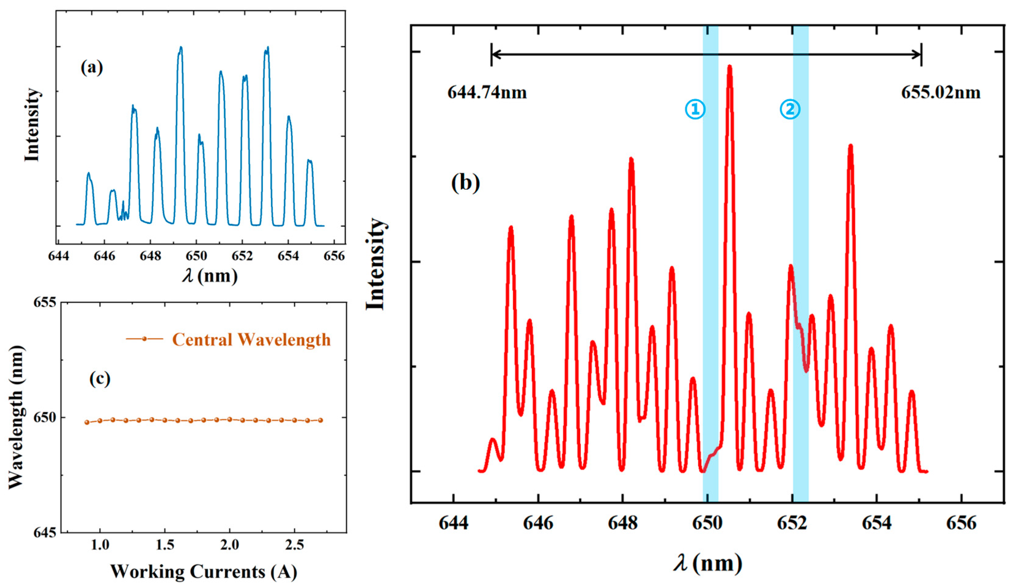
2Slow, were approximately 1.649 and 20.176, respectively. At 2.7 A, the free-running spectral width of the single-emitter was approximately 2 nm, with a total gain spectral width of 11 nm. The output surface of the 650 nm single-emitter was coated with a 0.5% antireflective film, and the rear cavity surface was coated with a 99.8% reflective film.
At present, the basic principles and mathematics of the dense spectral beam combining system have been the subject of international discussion, and were also elaborated in the previously published article [
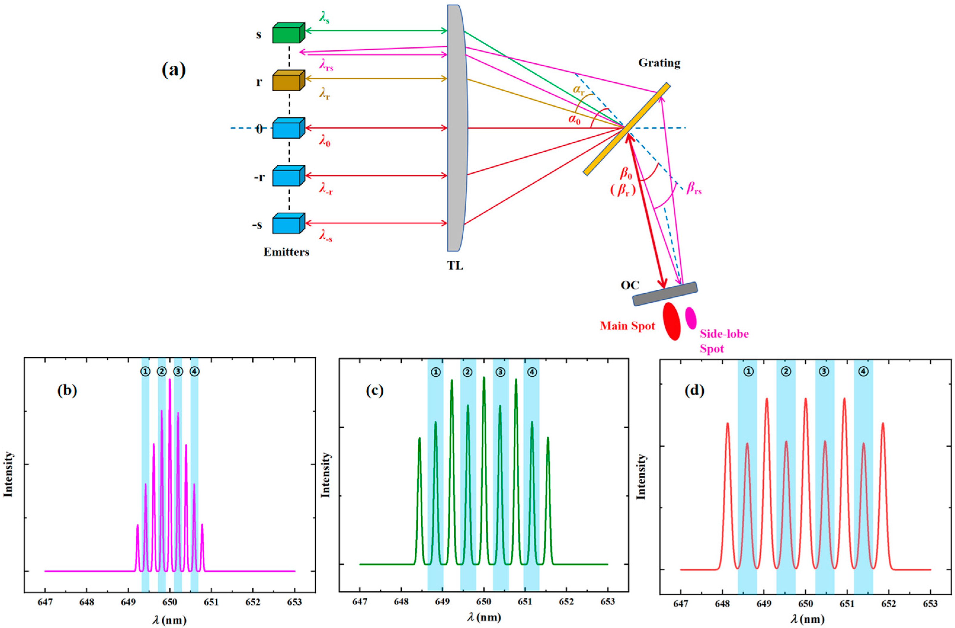
18] of our study. Therefore, instead of expanding the basic structure and principles of DSBC in this paper, we directly provide a schematic diagram of the DSBC system in the presence of crosstalk phenomena. As shown in Figure 2a, the blue dashed lines in the figure represent the optical axis as well as the optical normal of the grating and the output coupler (OC), respectively. In Figure 2a, there are 2s + 1 COS semiconductor emitters, the focal length of the transform lens (TL) is f, the diffraction grating period is Λ, and the spacing between each emitter is h. The visible red-light output from the central level 0th emitter has an incidence angle of α0 and a diffraction angle of β0 with respect to the grating normal. Based on the Littrow structure that is to be satisfied for DSBC, we know that the diffraction angles of all emitters, such as the -sth emitter, the -rth emitter, the rth emitter, and the sth emitter, are β0. From this, we can determine the specific value of the Littrow angle corresponding to the system, as well as the final locked wavelength for each level (ith) of the emitters by using Equations (1) and (2):
θ Littrow = α 0 = β 0 = β r = arcsin λ 0 2 Λ ,
λ i = λ 0 + i Λ h f cos α 0 i h f .
In the absence of feedback crosstalk, the emitters of each level are locked to oscillate at the corresponding wavelength. (For instance, the rth level emitter is locked to oscillate at λr.) In the schematic presented in Figure 2a, we mainly show the crosstalk generated between the rth emitter and the sth emitter. Due to the divergence and deviation of the light source or the optical path, the output light of the rth emitter (brown line) may return to the sth stage emitter (green line) after being partially reflected by the OC. Eventually, a steady oscillating crosstalk light (pink line) is formed between the two emitters. According to the formula given in a related crosstalk paper [19], we can conclude that the equivalent locked wavelength of the crosstalk beam can be obtained from Equation (3):
λ rs = λ r + λ s 2 .
Since the beam is actually output from the rth emitter but is finally locked to a wavelength of λrs, the crosstalk beam (pink line) is not entirely consistent with the Littrow structure through the diffraction grating. The diffraction angle of the crosstalk beam βrsβ0 results in an angle between the crosstalk beam (pink line) and the main combining beam (thick red line). Finally, as shown in Figure 1a, the crosstalk beam forms a pink side-lobe spot next to the main red spot. The same occurs for other cases of crosstalk beams. In order to be consistent with the experimental structure we designed, we set the central wavelength λ0 of the light source to be 650 nm, the spacing between the centres of the emitters to be 1 mm, and the grating period Λ to be 450 nm.
For the purpose of making the results clearer, we only set up five emitters in the simulations. The emitter levels were −2nd, −1st, 0, 1st, and 2nd. From the previous experimental results [18], we know that the main reason for the initial existence of large crosstalk is the long optical path of the system. Thus, we first need to reduce the optical path of the whole structure, which requires us to choose a transform lens with smaller focal lengths. We use the simulation model to further simulate the TL with different focal lengths (600~100 mm). It is worth noting that the intensities at all levels are expressed using normalised intensities. Here, representative spectral results of 600 mm, 300 mm, and 250 mm are shown in Figure 2b–d. The white background peaks in the figure represent the case of normal oscillation, while the light blue background peaks represent the case of crosstalk oscillation. It can be noticed that when the focal length is 600 mm, the intensity of the crosstalk oscillation is even greater than that of the normal oscillation. When the focal length is reduced to 300 mm, it can be observed that the crosstalk intensity is significantly weakened, indicating that reducing the focal length helps to weaken the crosstalk phenomenon. Further, when the focal length is reduced to about 250 mm, the crosstalk intensity is lower than the normal beam peak intensity. It is worth noting that each locking wave peak width is inversely related to the transform lens’s focal length. The longer the transform lens focal length, the narrower the locking wave peak width. Although further reducing the focal length of the transform lens can directly attenuate the intensity of crosstalk, we know through Equation (2) that the smaller focal length of the TL corresponds to the larger total spectral width of the combining beam. COS semiconductor lasers, on the other hand, have a fixed gain spectrum width, so the number of emitters that can participate in beam combining decreases, resulting in a significant decrease in the total output power. Therefore, we set the focal length of the converging lens to 250 mm, and the remaining crosstalk was solved by designing the imaging and compression telescope module (the specific principles and parameters will be described in the next section).

2.2. Experimental Setup

In this section, we will elaborate on the specific principles of the experimental system as well as the component parameters. 
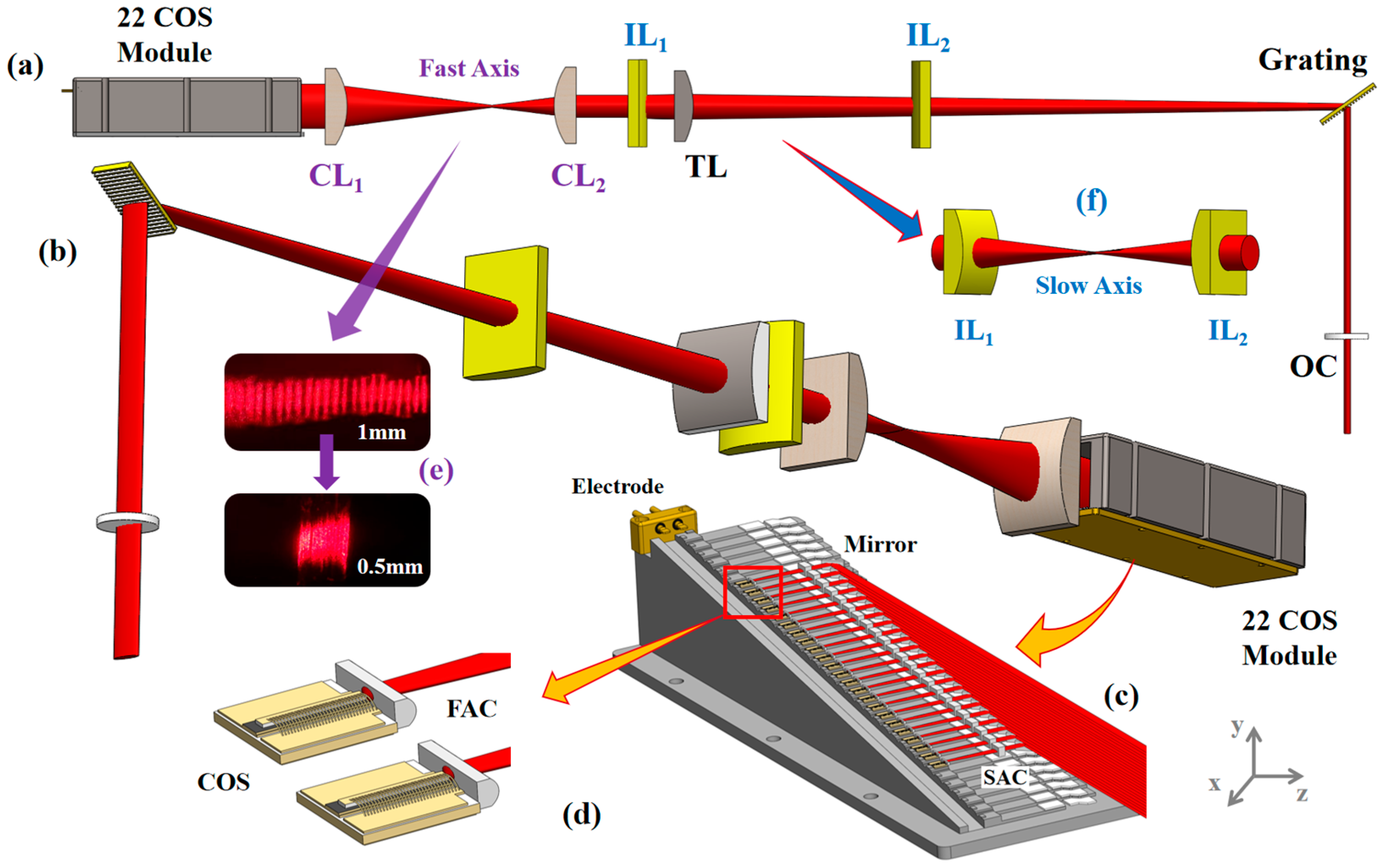
Figure 3a,b show the CM&IM DSBC system in the yoz planar schematic and 3D stereoscopic schematic. The system consists of four main modules. The first part is a 22,650 nm COS single-emitter module. In this case, the number of COS single-emitters is mainly determined using Equation (2) and the gain spectral width, which will be explained in detail later. The second part is a beam compression telescope module (purple). The third part is the imaging module (blue). The fourth part is the traditional DSBC module. The traditional DSBC module consists of a transform lens (TL), a diffraction grating, and an output coupler (OC). The transform lens is made of N-BK7, with a curvature radius of about 129.2 mm and an effective focal length of about 250 mm. The apertures of the TL in the diffractive (fast axis, y) and non-diffractive (slow axis, x) directions are 60 mm and 62 mm, respectively. The diffraction grating is a 2500 line/mm transmission diffraction grating from Gitterwerk, Germany, with a period Λ of 400 nm and a diffraction efficiency of about 93.5% for the TE-polarised (S) beam at 600~700 nm. The apertures of the grating in the diffractive (fast axis, y) and non-diffractive (slow axis, x) directions are 30 mm and 15 mm, respectively. The custom-made output coupler is 55 mm in diameter and coated with a 10% @ 600~700 nm reflective film on the laser-incidence side. Both side of the TL and the rear surface of the OC are coated with 99.8% @ 600~700 nm transmittance enhancement film. The internal structure of the 22 COS single-emitter module and the partial enlargement of the COS single-emitter are shown in Figure 3c,d. As can be seen from the figures, 22 COS single-emitters are soldered to a stepped water-cooled brass base using silver-tin solder, with spacings between the fast-axis and slow-axis directions of 1 mm and 10 mm, respectively. Each COS single-emitter is collimated by an aspherical fast-axis collimator (FAC) with a focal length of 256 μm, and then by a slow-axis collimator (SAC) with a focal length of 20 mm. After this, they are reflected by a 7 mm total reflection mirror with a 45° position. Finally, all 22 collimated red laser beams are deflected by 90° and aligned in the fast-axis direction for output. The FACs, SACs, and reflection mirrors are fixed to the cooling base using UV adhesive and are made of fused silica. The front and rear surfaces of the collimators are coated with 99.8% @ 600~700 nm transmittance enhancement film.
A picture of the actual output beam spot of the 22 COS module before and after passing through the compression telescope module (CM) is shown in Figure 3e. The telescope module consists of two spherical column lenses made of fused silica with effective focal lengths of 150 mm and 75 mm, respectively. The 150 mm lens was made of N-BK7 with a curvature radius of about 77.5 mm and an effective focal length of about 150 mm. The apertures of the 150 mm lens in the diffractive (fast axis, y) and non-diffractive (slow axis, x) directions were 100 mm and 90 mm, respectively. The 75 mm lens was made of H-K9L, with a curvature radius of about 38.8 mm and an effective focal length of about 75 mm. The apertures of the TL in the diffractive (fast axis, y) and non-diffractive (slow axis, x) directions were 53 mm and 50.8 mm, respectively. The converging direction of the column lenses was placed along the fast-axis direction, which achieved the purpose of reducing the beam spacing in the fast-axis direction by half. As can be seen in Figure 3e, the output beam spacing of 1 mm was successfully reduced to 0.5 mm after passing through the compression telescope module, and it is worth noting that the difference in the size of each spot in the figure was due to the optical path difference in the stepped structure. Combined with Equation (2), we know that when the beam spacing h is reduced from 1 mm to 0.5 mm, the corresponding total spectral peak spacing is reduced by half. Therefore, at a constant gain spectral width, the number of COS single-emitters involved in the system can be doubled compared to those of the structure without CM. It should be noted here that the IM DSBC system represents the CM&IM DSBC system without the compression telescope module (CM). This solves the problem of the large reduction in output power associated with reducing the focal length of the TL. Taking the above parameters (h = 1 mm; f = 250 mm; α0 = 54.5°, Λ = 400 nm) into Equation (2), the peak-to-peak spacing of the spectrum was calculated to be about 0.93 nm. With a gain spectral width of 11 nm, the DSBC system without CM allows up to 11 COS single-emitters to participate in the process. Therefore, with the addition of the 1/2 beam compression telescope module, it is expected that 22 COS single-emitters should be involved in the beam combining process.
We know from the simulation results in the previous section that the crosstalk phenomenon still exists in the spectrum of the 250 mm transform lens. In the simulation, we can observe that when the focal length of the TL is less than 100 mm, the system will no longer experience the crosstalk phenomenon. When looking at the analysis of the principle of crosstalk phenomenon presented in the previous section and the actual experimental structure, the main reason for crosstalk in this structure is found to be that the beam is constantly dispersed in the direction of the slow axis, which leads to a larger spot size. Therefore, an additional imaging module (IM) is needed to reduce the optical path in the slow-axis direction by 150 mm, as shown in the 3D schematic of the imaging module in Figure 3f. The imaging module consists of two 75 mm column lenses, consistent with the 75 mm lens in the CM. The converging direction of the column lenses is placed along the slow-axis direction to reduce the optical path of the whole system by 150 mm in the slow-axis direction. It is worth noting that the imaging module should normally be placed in front of the transform lens, but since the transform lens is optimally spaced at 250 mm from the 22 COS module and the CM occupies a total distance of 225 mm, the space before TL is not enough for a whole IM. Furthermore, it is important to keep all mirrors as far away as possible from the more fragile diffraction gratings. Therefore, in this imaging module, the first column lens was placed in front of the transform lens and the second column lens was placed behind the transform lens. Since the TLs converge in the fast-axis direction, they do not affect the imaging process in the slow-axis direction. The front and rear surfaces of the four column lenses in the CM and IM were coated with 99.8% @ 600~700 nm transmission enhancement film. All the experimental results are shown and analysed in the next chapter.

3. Results and Discussion

The output power and DSBC efficiency results of the CM&IM DSBC system were plotted as shown in Figure 4a and Figure 5a. The DSBC efficiency represents the ratio of the combined beam output power of the CM&IM DSBC system to the free-running power of the 22,650 nm COS single-emitters. The E-O efficiency represents the ratio of the combined beam output power of the CM&IM DSBC system to the total electrical input power from the power supply. When the working current is 0.9 A and the working voltage is about 42.729 V, the system exceeds the threshold current and enters normal operation. At this time, the 22,650 nm COS single-emitters’ free-running power is about 2.794 W, and the output power of the CM & IM DSBC system is about 2.642 W. At this time, the CM & IM DSBC system DSBC efficiency is about 94.58%, while the E-O efficiency is about 6.71%. When the working current reaches 2.7 A, the working voltage is about 46.206 V. At this time, the free-running power of 22,650 nm COS single-emitters is about 34.106 W, and the output power of the CM&IM DSBC system is about 29.984 W. The DSBC efficiency of the system is about 87.93%, while the E-O efficiency is about 24.03%. Throughout the process, we can observe that the E-O efficiency is basically consistent with the E-O efficiency of a COS single-emitter, so we will not analyse this too much here. Regarding the DSBC efficiency, the figure shows that this decreases from high to low, and finally stabilises. This is due to the fact that the threshold current of the whole system is inversely related to the system cavity length and the equivalent reflectivity. After adding the external cavity DSBC system, the system cavity length and equivalent reflectivity both increase compared to the results obtained for the COS single-emitter. This reduces the threshold current of the whole system and causes the system to start realising the output oscillation earlier. As a result, the DSBC efficiency of the entire CM&IM DSBC system is greater when the working current is 0.9~1.1 A. As the working current continues to increase, the entire system resumes normal output, but all types of intracavity and all cavity surface losses (surface loss is the energy lost due to the non-ideal reflection or transmission of light at the mirror surface of a resonant cavity) increase with the working current. Therefore, when the working current is 1.2~1.8 A, the DSBC efficiency of the whole CM&IM DSBC system is in an unstable state, fluctuating in the range 85~89%. Finally, as the working current increases to the high current stage, the output and loss of the whole CM&IM DSBC system reach a balance. Therefore, when the working current is 1.9~2.7 A, the DSBC efficiency of the whole system is stable at approximately 87~88%.
A comparison of the results of the output power of the CM&IM DSBC system, the IM DSBC system, and the traditional DSBC system is shown in Figure 4b and Figure 5b. The results for the traditional DSBC system were directly obtained from the experimental results of the 650 nm DSBC first realised by our team last year [18]. Here, we only analyse cases in which each system is able to operate stably at the maximum operating current. When the maximum operating current of the conventional DSBC system of 2.0 A is reached (the first version of the COS module used in traditional DSBC systems has a maximum working current of 2.0 A), the combined beam output powers of the CM&IM DSBC system, the IM DSBC system, and the traditional DSBC system are 23.855 W, 12.072 W, and 17.742 W, respectively. The combined output power of the IM DSBC system is reduced by more than 31% compared to the traditional DSBC system. This is due to the fact that the IM DSBC system incorporating only the imaging module has only 11 COS single-emitters involved in the combining beam due to the reduced focal length of the transform lens, which can be seen in the spectral results of the IM DSBC system presented in Figure 6a. Therefore, although the structure does achieve the desired crosstalk elimination results, the number of COS single-emitters involved in the beam combining is much smaller than that of the traditional DSBC beam combining system, resulting in a substantial reduction in the beam power. At the same working current, the combined output power of the CM&IM DSBC system is increased by more than 125% and 53% compared to that of the IM DSBC system and the traditional DSBC system, which is a very significant increase in output power. This indicates that the compression telescope module we added successfully increased the number of COS single-emitters involved in the beam combining process to even more than the number of single-emitters in the traditional DSBC system [18], consistent with the expected results achieved when we initially designed the system. When the working current increased to 2.7 A, the CM&IM DSBC system achieved an significant increase in the output power of about 129.12% compared to the IM DSBC system, which further validates the excellence of the compression telescope module. The results will be further analysed using the spectral results.
A plot of the spectral results of the IM DSBC system mentioned in the previous paragraph is shown in Figure 6a. As can be seen from the figure, there are 11 wave peaks that oscillate completely independently. This indicates that there are 11 COS single-emitters involved in the system within the gain spectral range at a 250 mm focal length. This is consistent with the calculations we performed in the experimental setup. The spectral results of the CM&IM DSBC system are shown in Figure 6b. From the figure, we can see that the number of independently oscillating wave peaks increases substantially compared to the IM DSBC system. After careful identification, there are 21 independently oscillating peaks in the figure, with a total spectral width of about 10.28 nm, which is basically the same as the calculation results obtained in the previous chapter. The missing peak is at position ① against a light blue background in the figure. A closer look at this position reveals that the intensity of its neighbouring peaks abnormally increased compared to the other peaks. Therefore, the main reason for the missing peaks is that although the COS single-emitter ensures accuracy when adjusting the directivity, the curing offset of the UV adhesive, as well as the aberration brought by the addition of the compression lenses, may lead to large errors. Ultimately, the feedback beam from the missing single-emitter may have been fed back into a single-emitter that is not adjacent to the missing single-emitter after the OC. Then, according to Equation (3), the locked centre wavelength of the oscillation formed between these two non-adjacent emitters is the same as the locked wavelength of the emitter in the middle, which results in a missing wave peak in the final spectrum. For instance, if the 1st single-emitter feeds back into the 3rd single-emitter, then the locked wave peak of the 1st emitter overlaps with that of the 2nd emitter, resulting in a missing 1st wave peak. A slight degree of crosstalk exists at location ②, presented against a light blue background in the figure; the main reason for this is essentially the same as the reason for that at location ①. Figure 6c presents the results of the central wavelength of the CM&IM DSBC system spectra for different working currents. From the figure, it can be seen that as the operating current increased from 0.9 A all the way up to 2.7 A, the central wavelength of the spectra remained around 650 nm. This phenomenon shows that the entire CM&IM DSBC system’s final spectrum does not exhibit a red-shift phenomenon, and the beam combining effect is very stable.
The results of the beam quality factor measurements for the CM&IM DSBC system are shown in Figure 7. From the figure, it can be seen that the fast-axis CM&IM DSBC system beam quality factor M2Fast is about 1.653 when the working current is 0.8 A. At this time, the deterioration is only 0.364% compared with that of a COS single-emitter. As the working current increases, the combined beam-quality factor increases. This is mainly due to the fact that some semiconductor laser models appear only at a high working current, resulting in a degradation in the beam quality of the combined beam. Finally, the fast-axis and slow-axis beam-quality factors of the CM&IM DSBC system, M2Fast and M2Slow, are 1.701 and 20.989 when the working current reaches 2.7 A. The deterioration of the beam-quality factor in the fast-axis and slow-axis directions is no more than 5% in comparison with that of a COS single-emitter. This indicates that the beam quality of the combined beam is excellent.
B = P λ 0 2 M 2 Fast M 2 Slow
Equation (4) shows the laser beam brightness formula, where B is the beam brightness symbol and P is the system’s combined beam output power. When the working current is 2.0 A, based on Equation (4), the CM&IM DSBC system beam brightness can be obtained and is about 159.647 mW·cm−2·sr−1. Compared with the traditional DSBC system [18], the beam brightness increases by more than 29.37%. When the working current reaches 2.7 A, the CM&IM DSBC system beam brightness is about 198.777 mW·cm−2·sr−1. Compared with a COS single-emitter, the beam brightness is enhanced by more than 22 times.

4. Conclusions

In this paper, a 650 nm dense spectral beam combining (DSBC) system based on the combination of a compression telescope module (CM) and an imaging module (IM) (CM&IM DSBC system) was successfully constructed based on a 22,650 nm COS single-emitter module. For the first time, the system achieves a high-power non-crosstalk beam combining output in the visible-red band, with a maximum beam combining output power of 29.984 W and a DSBC efficiency of about 87.93%. Compared with the 650 nm traditional DSBC first realised by our group [18], this system solves both the crosstalk problem of a larger optical path and the decrease in beam power caused by the direct reduction in the optical path. The final output power and beam efficiency are improved by more than 53% and 10%, respectively. The beam brightness of the final combined beam is improved by nearly 30%. Compared to a COS single-emitter, the brightness is improved by more than 22 times. This achievement provides new possibilities for the subsequent experimental research and product development of higher-power visible-red-band DSBC systems that can be used for the industrial processing and pumping of solid-state lasers. In subsequent studies, we plan to optimise the system through a combination of internal and external approaches. First, we will optimise the internal chip structure of the COS single-emitter to improve the output power and gain spectral width, while reducing the divergence angle. Second, for the external structure, we plan to add multiple rows of COS single-emitter modules and customise the optical components for higher precision. Ultimately, we hope to achieve the goal of increasing the output power and brightness of the system and aim to achieve productisation in the future.

Author Contributions

Conceptualization, B.Z. and W.Z. (Wanhua Zheng); methodology, B.Z., W.Z. (Weiqiao Zhang), and M.H.; Software, N.Z., A.C., B.Z., and F.T.; investigation, B.Z., L.M., A.Q., and J.L.; writing—original draft preparation, B.Z.; writing—review and editing, J.L., B.Z., and N.Z.; supervision, J.L. and W.Z. (Wanhua Zheng); funding acquisition, W.Z. (Wanhua Zheng) and X.Z. All authors have read and agreed to the published version of the manuscript.

Funding

This work is supported by Key Research and Development Program of Shandong Province (2023ZLYS03) and Key Research and Development Program of Shandong Province (2022CXGC020104).

Institutional Review Board Statement

Not applicable.

Informed Consent Statement

Not applicable.

Data Availability Statement

Data are contained within the article.

Conflicts of Interest

The authors declare no conflicts of interest.

References

  1. Littman, M.G.; Metcalf, H.J. Spectrally narrow pulsed dye laser without beam expander. Appl. Opt. 1978, 17, 2224–2227. [Google Scholar] [CrossRef] [PubMed]
  2. Cook, C.C.; Fan, T.Y. Spectral beam combining of Yb-doped fiber lasers in an external cavity. Opt. Photonics News 1999, 10, 411. [Google Scholar]
  3. Fan, T.Y.; Sanchez, A.; Daneu, V.; Aggarwal, R.; Buchter, S.; Goyal, A.; Cook, C. Laser beam combining for power and brightness scaling. In Proceedings of the 2000 IEEE Aerospace Conference, Big Sky, MT, USA, 25 March 2000; pp. 49–54. [Google Scholar]
  4. Zimer, H.; Haas, M.; Ried, S.; Tillkorn, C.; Killi, A.; Heinemann, S.; Negoita, V.; An, H.; Schmidt, B. Thin film filter wavelength-locked laser cavity for spectral beam combining of diode laser arrays. IEEE Photonics Technol. Lett. 2014, 26, 230–231. [Google Scholar]
  5. Haas, M.; Killi, A.; Tillkorn, C.; Ried, S.; Ginter, M.; Zimer, H. Thin-film filter, wavelength-locked, multi-laser cavity for dense wavelength beam combining of broad-area laser diode bars. Opt. Lett. 2015, 40, 3949–3952. [Google Scholar] [CrossRef] [PubMed]
  6. Haas, M.; Rauch, S.; Nagel, S.; Irmler, L.; Dekorsy, T.; Zimer, H. Thin-film filter wavelength-stabilized, grating combined, high-brightness kW-class direct diode laser. Opt. Express 2017, 25, 17657–17670. [Google Scholar] [CrossRef] [PubMed]
  7. Meng, H.C.; Ruan, X.; Du, W.C.; Wang, Z.; Lei, F.; Yu, J.; Tan, H. Scaling the spectral beam combining channel by multiple diode laser stacks in an external cavity. Laser Phys. Lett. 2017, 14, 045811. [Google Scholar] [CrossRef]
  8. Rieda, S.; Raucha, S.; Irmlera, L.; Rikels, J.; Killi, A.; Papastathopoulos, E.; Sarailou, E.; Zimer, H. Next generation diode lasers with enhanced brightness. Proc. SPIE 2018, 10514, 105140G. [Google Scholar]
  9. Yu, H.; Tan, S.Y.; Pan, H.D.; Sun, S.; Li, J.; Wang, J.; Zediker, M.S. Development of a 350 W, 50 μm, 0.15 NA wavelength stabilized fiber coupled laser diode module for pumping Yb-doped fiber laser. Proc. SPIE 2020, 11262, 112620V. [Google Scholar]
  10. Yu, H.; Tan, S.Y.; Pan, H.D.; Sun, S.; Li, J.; Wang, J. High efficiency 600 W, 100 μm wavelength stabilized fiber coupled laser diode module for fiber laser pumping. Proc. SPIE 2021, 11668, 116680E. [Google Scholar]
  11. Yu, H.; Tan, S.Y.; Pan, H.D.; Sun, S.; Lin, P.; Hu, H.; Wang, J.; Zediker, M.S.; Zucker, E.P. High-brightness fiber-coupled diode module using dense wavelength beam combining technology based on single emitter for material processing and fiber amplifier pumping. Proc. SPIE 2022, 11983, 119830A. [Google Scholar]
  12. Xing, X.X.; Zhou, X.Y.; Qu, H.W.; Zhang, W.; Meng, L.; Liu, J.; Wang, Y.; Zheng, W. High beam quality broad-area diode lasers by spectral beam combining with double filters. Chin. Opt. Lett. 2022, 20, 061402. [Google Scholar]
  13. Tsutsumi, F.; Kato, N.; Kobata, N.; Imoto, D.; Miyano, K.; Kitagawa, H.; Halle, C.; Nobuoka, M.; Kaierle, S.; Heinemann, S.W. Remote Laser Processing of Highly Reflective Materials with Ultra-Bright Lasers Operating at 445nm. Proc. SPIE 2022, 11994, 119940. [Google Scholar]
  14. Zhu, Z.D.; Wu, W.C.; Wang, L.D.; Hui, Y.; Lei, H.; Li, Q. Dual-wavelength laser source by spectral beam combining of two Nd:YAG pulse lasers. Appl. Opt. 2023, 62, 1939–1942. [Google Scholar] [CrossRef]
  15. Meng, L.Q.; Zhang, W.Q.; Liu, J.; Cao, P.; Wang, Y.; Zhou, X.; Zheng, W. High-brightness and high-efficiency diode laser module based on a coherent—Spectral beam combining external cavity. Chin. Opt. Lett. 2024, 22, 121403. [Google Scholar] [CrossRef]
  16. Yang, L.L.; Wang, X.; Li, X.H.; Dong, L. Numerical analyses of a mid-IR metasurface spectral beam combiner with high efficiency and low phase distortion. Opt. Express 2025, 33, 5509–5524. [Google Scholar] [CrossRef]
  17. Peng, J.; Fang, Y.Y.; Lin, Z.J.; Qi, Y.; Yan, B.; Zhou, M.; Han, Z.; Wang, Q.; Wang, Y. Thermal Effects and Output Power Dips in Alexandrite Lasers with F-P Cavity. Chin. J. Lasers 2023, 50, 1901007. [Google Scholar]
  18. Zhao, B.X.; Zhang, W.Q.; Zhou, X.Y.; Liu, J.; Meng, L.; Hu, M.; Zhang, N.; Chen, A.; Zheng, W.-H. High beam quality, high brightness dense spectral beam combining of 650 nm laser diode module. Opt. Express 2024, 32, 35840–35853. [Google Scholar] [CrossRef]
  19. Wu, Z.; Yang, L.; Zhang, B. Effect of crosstalk on spectrally combined beam properties and efficiency in external cavities. Appl. Opt. 2017, 56, 2834–2842. [Google Scholar] [CrossRef] [PubMed]
Figure 1. Structure and performance of the 650 nm single-emitter used in this experiment. (a) Semiconductor laser chip structure and (b) COS single-emitter P-I plot.
Photonics 12 00605 g001
Figure 2. Crosstalk simulation and simulation results of combining spectra corresponding to different TL: (a) schematic diagram of the DSBC system in the presence of crosstalk, (b) 600 mm TL, (c) 300 mm TL, and (d) 250 mm TL. TL, transform lens; OC, output coupler.
Photonics 12 00605 g002
Figure 3. Diagram of the actual experimental structure. (a) CM&IM DSBC system yoz planar schematic; (b) CM&IM DSBC system 3D stereoscopic schematic; (c) internal structure diagram of the 22 COS module; (d) partial enlargement view of the COS single-emitter and the fast-axis collimator; (e) actual beam spot demonstration of the compression telescope module; and (f) 3D schematic of the imaging module. CL, compression lens; IL, imaging lens; TL, transform lens; OC, output coupler; FAC, fast-axis collimator; SAC, slow-axis collimator.
Photonics 12 00605 g003
Figure 4. Output power results. (a) CM&IM DSBC system’s working voltage and output power results; (b) a comparison of the output power between the CM&IM DSBC system, the IM DSBC system, and the traditional DSBC system.
Photonics 12 00605 g004
Figure 5. Percentage results. (a) DSBC efficiency and E-O efficiency results for the CM&IM DSBC system; (b) the percentage comparison of the output power between the CM&IM DSBC system, the IM DSBC system, and the traditional DSBC system.
Photonics 12 00605 g005
Figure 6. Spectral results: (a) IM DSBC system spectral results at 2.7 A; (b) CM&IM DSBC system spectral results at 2.7 A (labels ① and ② refer to two locations in the spectrum where anomalies exist); and (c) spectral stability measurements.
Photonics 12 00605 g006
Figure 7. The beam-quality factor M2 results. (a) M2 of a CM&IM DSBC system at maximum current, and (b) M2 of CM&IM DSBC system at different working currents. Deterioration is defined as the ratio of the difference between the combined beam quality and the single-emitter beam quality to the single-emitter beam quality.
Photonics 12 00605 g007
Disclaimer/Publisher’s Note: The statements, opinions and data contained in all publications are solely those of the individual author(s) and contributor(s) and not of MDPI and/or the editor(s). MDPI and/or the editor(s) disclaim responsibility for any injury to people or property resulting from any ideas, methods, instructions or products referred to in the content.

