Article

Research on Wavelength-Shifting Fiber Scintillator for Detecting Low-Intensity X-Ray Backscattered Photons

1
MOE Key Laboratory of Advanced Micro-Structured Materials, School of Physics Science and Engineering, Tongji University, 1239 Siping Road, Shanghai 200092, China
2
National Key Laboratory of Science and Technology on Near-Surface Detection, Wuxi 214000, China
*
Authors to whom correspondence should be addressed.
Photonics 2025, 12(6), 567; https://doi.org/10.3390/photonics12060567
Submission received: 30 April 2025 / Revised: 29 May 2025 / Accepted: 3 June 2025 / Published: 4 June 2025
(This article belongs to the Special Issue Optical Technologies for Measurement and Metrology)

Abstract

:
High-sensitivity fiber scintillator detectors are the key to achieving high signal-to-noise ratio and high contrast imaging in X-ray Compton backscattering technology. We established a simulation model of wavelength-shifting fiber (WSF) scintillator detectors based on Geant4. The influences of ray source energy, detection area, number of WSFs, and coupling mechanism on detection efficiency were simulated. By using the epoxy resin coupling method, the transmission efficiency between the WSF and scintillator was increased from 4.56% to 19.79%. Based on the simulation data, we developed an X-ray WSFs scintillator detector, built an X-ray backscattering imaging experimental system, obtained high-contrast backscattering images, and verified the performance of the detector.

1. Introduction

The flying spot scanning X-ray Compton backscattering imaging technology has advantages in the fields of medical diagnosis, security screening, and industrial non-destructive testing due to its high sensitivity in detecting low atomic number (low Z) materials [1]. Its physical mechanism relies on the Compton scattering cross-section and electron density [2]. However, the scattering intensity is much lower than the transmission intensity [3,4], and the Compton backscattering is even weaker than the forward scattering. In the application of X-ray Compton backscattering imaging technology, to achieve high resolution, the flying spot scanning beam is only 1–2 mm. The incident light has a small light flux (only 10−3 to 10−5 of the transmission signal) [5,6], and the Compton backscattering signal is extremely weak. These two reasons result in very few effective photons backscattered from the inspected object. Therefore, a detector with extremely high detection sensitivity is required to achieve high signal-to-noise ratio and high contrast imaging [7,8,9].
At present, Compton backscattering detectors mainly adopt the combination method of organic plastic scintillators (such as BC-404, EJ-200) and photomultiplier tubes (PMTs) [10,11]. Their light yield (about 10,000 photons/MeV) and fast time response (decay time < 5 ns) make them the mainstream choice for large-scale security inspection and nuclear detection equipment. However, this technology is limited by the mismatch between the emission spectrum of the scintillator (peaking at 420–450 nm) and the quantum efficiency of the PMT photocathode (peaking at 350–400 nm), which leads to interface photon loss. Moreover, the vacuum tube structure of PMTs makes the detector thickness exceed 30 cm, which makes it difficult to adapt to small-sized devices [12,13,14]. Although the combination of inorganic scintillators (such as cesium iodide thallium) and silicon photomultiplier tubes (SiPM) can achieve small-sized and have a relatively high signal transmission efficiency [15], the effective detection area of the detector is small, and the collection solid angle is limited, resulting in a small number of Compton scattering signals received. Therefore, it is difficult to detect large-sized objects, which limits the wide application of this detector.
To address the aforementioned issues, this study employed a scintillator detector based on WSFs [16]. For this detector, the scintillator parameters, fiber parameters, and coupling methods determine the detection efficiency. This method is compared with the current related methods as shown in Table 1. Therefore, it is necessary to establish a simulation model to analyze the relationship between the detector performance and factors such as the scintillator parameters, the refractive index gradient of WSFs, and the coordinated design of the coupling agent.
This paper established a simulation model of WSF scintillator detectors based on Geant4 and simulated the detector from the aspects of X-ray photon interaction with scintillator and fluorescence photon transport. Based on the established model, the simulation was carried out on the reception and transmission process of Compton scattering signal under the conditions of ray energy, scintillator size, number of WSFs, and coupling mechanism. A Compton scattering efficiency of 25% was achieved, and by filling epoxy resin between the scintillator and the WSF, the photon transmission efficiency from the scintillator to the WSF was optimized from 4.56% to 19.79%. Based on the simulation data, an X-ray Compton scattering imaging system was designed and developed, and verification experiments were carried out to obtain Compton scattering images. The improvement effect of image quality was basically consistent with the simulation results. The research content of this paper can provide a reference for the design of high-resolution and high signal-to-noise ratio Compton imaging systems.

2. Model

Compared with the PMT scintillator, the WSF scintillation detection system (Figure 1) has the advantage of expanding the scintillation photon output area and improving the photon output efficiency. However, this method adds extra components, lengthens the photon transmission path, and the photons will pass through multiple interfaces during transmission, resulting in transmission loss. Therefore, optimizing the Compton scattering signal collection efficiency of this system while reducing the photon transmission loss from the scintillator to the PMT is the key to the research.
To solve the above problems, a Geant4 simulation model (version 11.2.0) was established, as shown in Figure 2. A cubic world volume with an edge length of 3 m was defined, and a scintillator was placed at the origin. The scintillator was 40 cm × 20 cm × 2 cm in size, made of polystyrene (light yield: 10,000 photons/MeV; refractive index: 1.58 at the emission peak of approximately 425 nm; density: 1.032 g/cm3; decay time: approximately 2.4 ns) [17,18]. Rectangular grooves were machined along the x-axis (length: 400 mm, radius: 0.51 mm) to accommodate WSF, and the number of grooves matched the number of WSFs.
A gamma-ray source with an energy range of 20 keV to 1 MeV was located at the coordinate (150, 0, −200) and emitted particles along the direction of (0, 0, −1). A Polymethyl Methacrylate (PMMA) scatter phantom (5 cm cube), which is sensitive to Compton scattering due to its low atomic number composition, was placed at (150, 0, a), where “a” represents the separation between the phantom and the scintillator along the z-axis. The WSF had a single-clad structure (total length: 1 m; radius: 0.5 mm), composed of a polystyrene core (radius: 0.48 mm; refractive index: 1.59; density: 1.05 g/cm3; absorption/emission peak: 430 nm/476 nm) and a PMMA cladding (thickness: 0.02 mm; refractive index: 1.49; density: 1.19 g/cm3; attenuation length: 3 m) [19,20,21]. The WSF was arranged along the x-axis, corresponding to the scintillator grooves. The surface of the scintillator was coated with an aluminum reflective layer with a reflectivity of 0.95. The inner wall of the scintillator hole was defined as a high transmission interface with a transmission rate of 0.95.
This model defines the following physical processes: (1) It defined the interaction between gamma particles and PMMA, including Compton scattering, Rayleigh scattering, photoelectric effect, and pair production. The number of Compton scattered particles in each event was recorded: (2) It defined the deposition and ionization excitation process of charged particles in the scintillator and recorded the number of Compton particles received by the scintillator and the photon yield of the scintillator. (3) The photon transmission from the scintillator to the WSFs included boundary reflection, refraction, and absorption attenuation, and the number of photons entering the WSFs from the scintillator was recorded. (4) After entering the WSFs, the photons will undergo fluorescence re-emission, during which the wavelength of the photons will change. Subsequently, the photons undergo total internal reflection within the WSFs. Finally, the number of photons at the end face of the WSFs was recorded to quantify the transmission efficiency of WSFs.
The simulation was carried out using the Geant4 toolkit, where the detector geometry was constructed with classes such as G4Box and G4Tubs to define the world volume, scintillator, and WSF structures. Materials were assigned using G4Material, with optical properties including refractive index, density, and attenuation length. A gamma-ray source was implemented via G4PrimaryGeneratorAction, emitting particles across a defined energy spectrum and direction. Photon interactions—including Compton scattering, photoelectric effect, Rayleigh scattering, and pair production—were modeled, along with optical processes like scintillation, boundary interactions, and wavelength shifting using G4Scintillation, G4OpBoundaryProcess, and G4OpWLS.
To evaluate detector performance, photon tracking and counting were conducted using G4Event, G4Track, G4Step, and user-defined actions such as UserSteppingAction and UserStackingAction. The simulation recorded photons at key stages: those scattered in the PMMA phantom, those generating scintillation light, photons entering the WSFs, and those reaching the fiber end face. By analyzing the number of photons at each stage, the system’s Compton scattering efficiency, scintillator-to-fiber coupling efficiency, and WSF transmission efficiency were quantitatively assessed. These metrics enabled the optimization of detector geometry, WSF configuration, and coupling methods.

3. Results and Discussion

In this study, we systematically investigated the influence of various parameters on the performance of the WSF scintillator detector. The results were analyzed and discussed, focusing on Compton scattering efficiency, geometric arrangement of WSFs, energy transfer between the scintillator and WSFs, and the overall photon transmission efficiency. An initial particle source emitting 100,000 particles was defined.

3.1. Compton Scattering Efficiency

Compton scattering efficiency reflects the scintillator’s capability to capture gamma photons through Compton scattering, with its magnitude dependent on gamma-ray energy, scintillator area, detection distance, and other parameters. The particle source emits a number of incident particles denoted as Nincident, of which NCompton undergo Compton scattering in PMMA, and NDetect are registered by the scintillator. In experiments with Nincident = 100,000, the Compton scattering efficiency is calculated using Equation (1):
η C o m p t o n = N Detect N i n c i d e n t

3.1.1. The Impact of Gamma-Ray Energy

As shown in Figure 3a, the Compton scattering efficiency exhibits a distinct energy dependence. It reaches a peak of 28.9% at 60 keV, as this energy range favors Compton scattering interactions over photoelectric absorption. When the energy of the radiation source is between 40 keV and 120 keV, the Compton scattering efficiency can all reach above 25%, but it drops to less than 15% at 500 keV and above, which is consistent with the theoretical prediction of the Klein–Nishina formula as Equation (2), indicating that highly penetrating photons are less likely to scatter effectively within the scintillator.
d σ K N d Ω = r e 2 2 1 1 + α 1 cos θ 2 1 + cos 2 θ + α 2 1 cos θ 2 1 + α 1 cos θ
where α = E0/mec2 is the energy of the incident photon in the unit of static energy of the electron, θ is the scattering angle, re is the classical electron radius, and d σ KN / d Ω is the Compton scattering cross-section, which means the probability of scattered photons produced by inelastic collision of photon and free electron in all directions. Additionally, the photon yield of the scintillator increases exponentially with energy for gamma-rays below 200 keV (Figure 3b), owing to the photoelectric effect dominates in this energy range, a large proportion of their energy is deposited in the scintillator material when interacting with it. Above 500 keV, the energy deposition becomes less significant, further decreasing the number of effective interactions between the photons and the scintillator material. These findings suggest that for optimal detection sensitivity, the energy of the incident X-ray source should be limited to below 200 keV, where both Compton scattering efficiency and photon yield are maximized.

3.1.2. The Impact of Scintillator Area

Figure 4 shows that at a detection distance of 10 cm, when the effective detection area of the scintillator increases from 200 cm2 to 1600 cm2, the efficiency rises from 8% to 26%. When the detection area is further expanded to 3200 cm2, the efficiency only slightly improves (28%), this is due to the fact that, as the detection area increases, the solid angle from which photons can be captured expands, but the efficiency gain is less significant once the solid angle reaches a saturation point (when scintillator area further increases, solid angle changes gradually slowly until it is basically saturated).
Moreover, as shown in Figure 4, when the scintillator area remains constant, increasing the distance between the scintillator and the object being detected reduces the number of Compton-scattered photons collected by the scintillator, but it also expands the system’s detection area. However, this leads to an increase in the diameter of the detection spot, thereby reducing the system’s resolution. Therefore, a trade-off needs to be made in system design: the optimal detection area should strike a balance between the sensitivity of signal detection and the spatial resolution required for imaging.

3.2. Scintillator-to-Fiber Transmission Efficiency

3.2.1. The Impact of the Number of WSFs

The geometric arrangement of WSFs plays a pivotal role in the efficiency of photon transmission from the scintillator. The results (Figure 5) show that increasing the number of WSFs leads to a linear increase in photon transmission efficiency, which can be explained by the increased contact area between the scintillator and the fibers. As more fibers are added, the probability of photons being captured by the WSFs increases. However, as the number of WSFs exceeds a certain threshold (approximately 80 fibers), the number of photons transmitted to the WSFs begin to approach saturation, where additional fibers do not significantly improve transmission efficiency. This indicates that when the scintillator’s photon yield is fixed, the system reaches an optimal photon collection area where further increases in fiber count do not lead to a linear improvement in efficiency.
The relationship between the number of fibers and photon transmission efficiency can also be explained by considering the optical path length and the number of interfaces a photon must traverse. With a larger number of WSFs, the photon path becomes increasingly complex, leading to potential photon losses at the fiber interfaces due to reflection and scattering. The results suggest a saturation point beyond which increasing the number of fibers only adds redundant collection paths, rather than enhancing performance.

3.2.2. The Impact of Scintillator–WSF Coupling Mechanism

The efficiency of photon transmission from the scintillator to the WSFs is significantly influenced by the coupling mechanism between the two components. Initially, when no coupling agent is used, only 4–5% of the generated photons are transmitted to the WSFs, primarily due to losses at the interface between the scintillator and the fiber, caused by Fresnel reflection and multiple internal reflections. To mitigate these losses, we employed an epoxy resin with a refractive index matching that of both the scintillator and the WSF (n = 1.5). The introduction of this epoxy resin substantially increased the photon transmission efficiency, improving it by a factor of nearly five, from 4.56% to 19.79% (Table 2). This improvement can be theoretically attributed to reduced photon reflection at the interface, as the refractive index matching minimizes the angle of total internal reflection, facilitating more efficient photon transport into the fibers.
Light transmission at material interfaces suggests that optimal coupling occurs when the refractive index of the materials is closely matched. The epoxy resin effectively reduces the optical mismatch between the scintillator and the WSFs, leading to a significant enhancement in photon collection efficiency. This aligns with the established principles of optical fiber coupling, where minimizing the refractive index difference between the materials involved minimizes photon losses due to reflection.

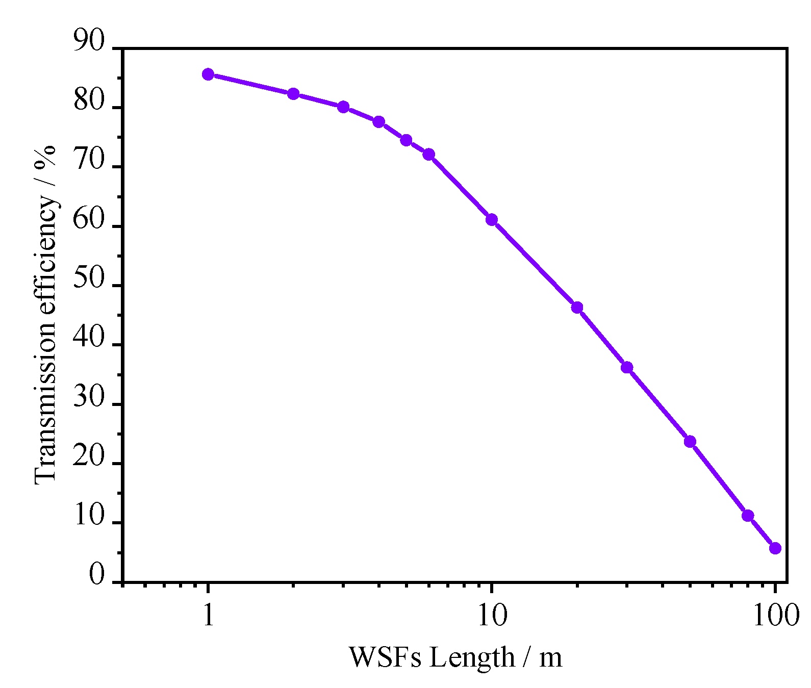
3.2.3. The Impact of WSFs Length
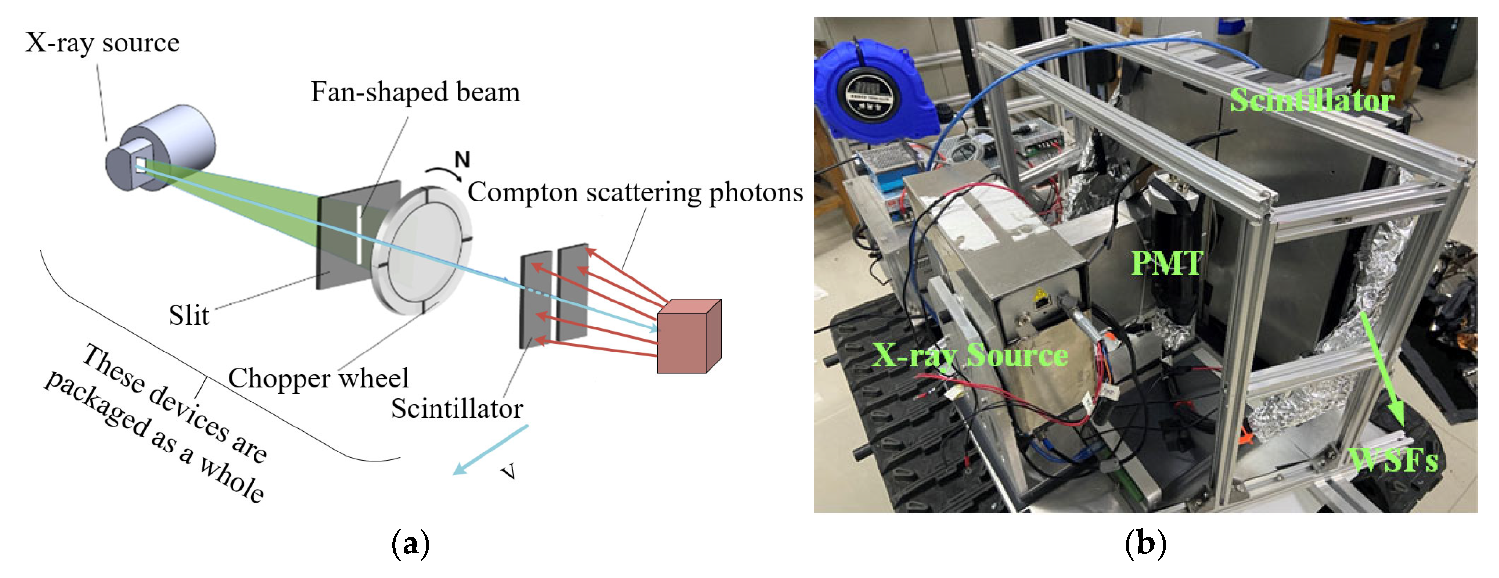
As shown in Figure 6, the transmission efficiency of WSFs decreases with increasing fiber length. This can be explained by the cumulative photon losses due to Rayleigh scattering, absorption, and other inherent material losses that accumulate as the length of the fiber increases. The Beer–Lambert law provides a theoretical framework for understanding how the attenuation of light in optical fibers increases with length. To maintain a sufficiently high transmission efficiency, it is advisable to limit the length of WSFs to below 10 m in practical applications, as longer fibers result in exponentially decreasing efficiency.
In summary, the integration of WSFs with scintillator detectors significantly enhances the detection of Compton scattering signals in X-ray backscattering imaging. Theoretical analysis of the system, including the energy dependence of Compton scattering efficiency, the optimal geometric arrangement of WSFs, and the importance of coupling efficiency, has provided insights into how the system’s performance can be maximized. By optimizing the coupling mechanism with epoxy resin, adjusting the number of WSFs, and considering the impact of fiber length, we achieved an improvement in photon transmission efficiency. These findings not only support the experimental data but also offer a theoretical framework for further improvements in the design of high-sensitivity X-ray imaging systems.

4. Experiments

We developed the WSF detector system. The scintillator material used is the HND-S2 plastic scintillator, manufactured by Beijing Gaonengkedi Company, Beijing, China. The WSF model is Y-11 (200), produced by Kuraray Co., Ltd., Tokyo, Japan. Based on the simulation results, we designed the single detector area to be 40 cm × 20 cm. Using two detectors, the total effective detection area can reach 1600 cm2. A size that is too large not only does not significantly improve the signal collection efficiency but also increases the system volume. We chose 40 and 80 WSF, respectively, for comparison, as the simulation results indicated that a photon transmission efficiency close to saturation can be achieved with around 80 WSF. The developed WSF detector is shown in Figure 7.
Following the aforementioned simulations, a system for acquiring Compton scattering signals was established. This study primarily investigated the effects of detection area and optical fiber density on the quality of Compton scattering images. Incident X-rays were modulated using flying-spot scanning to emulate the collimated particle source beam in the simulation model, as schematically illustrated in Figure 8a. Subsequently, the experimental platform was constructed (Figure 8b), and the scintillator and WSF were shielded and protected. The total thickness of the scintillator and shielding device was 8 cm, and verification experiments were conducted using this device.

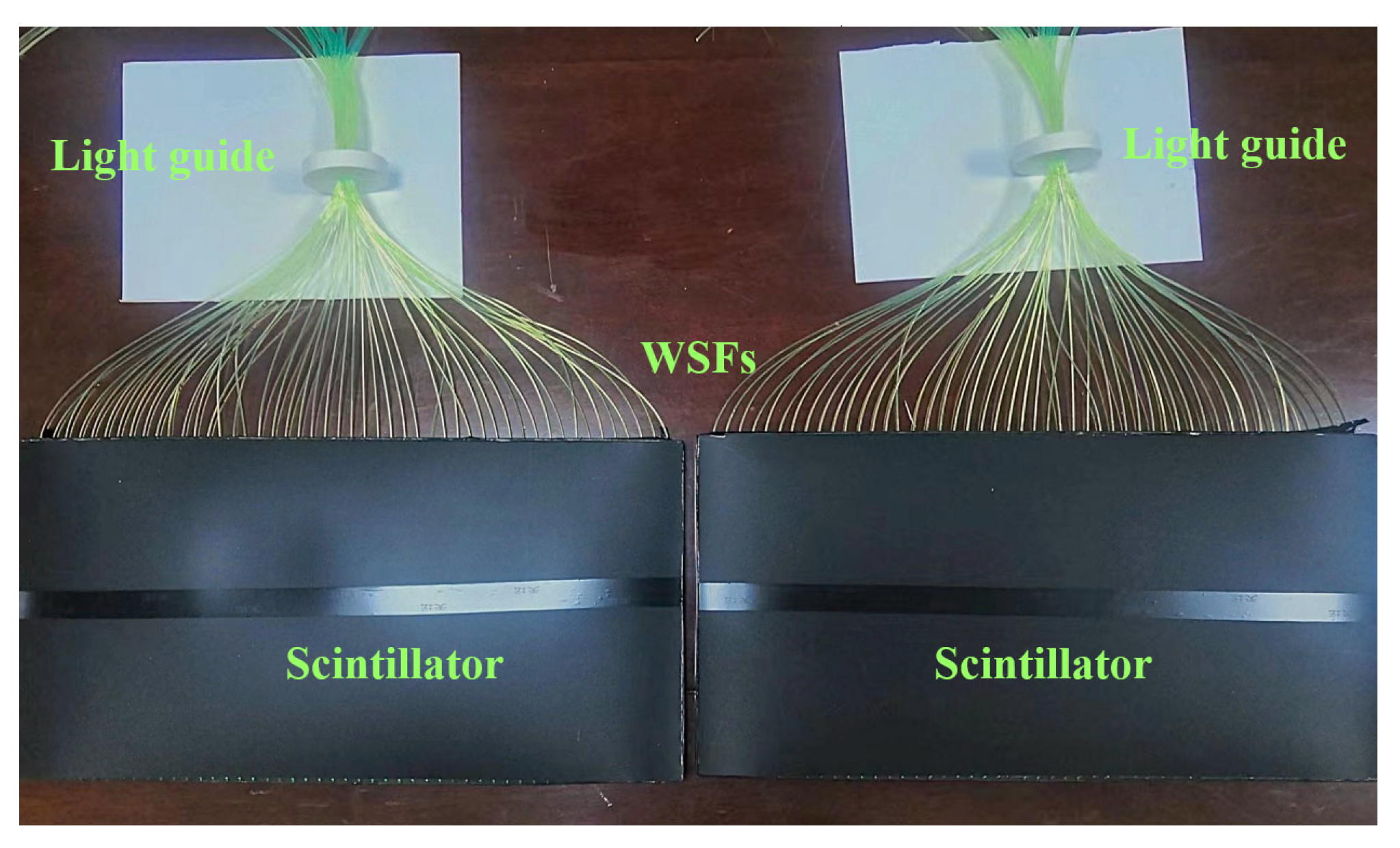
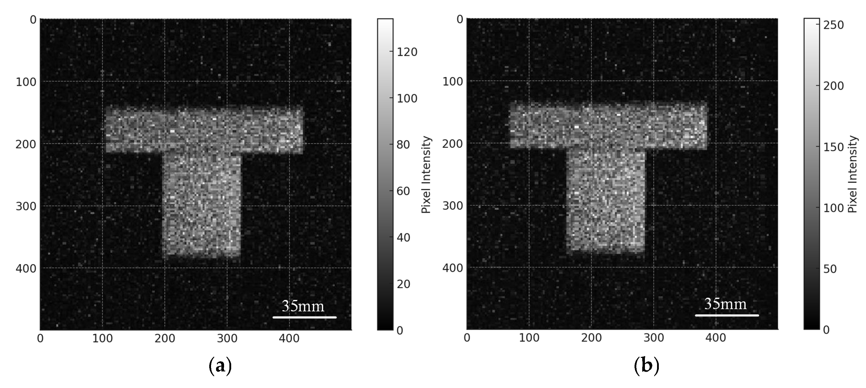
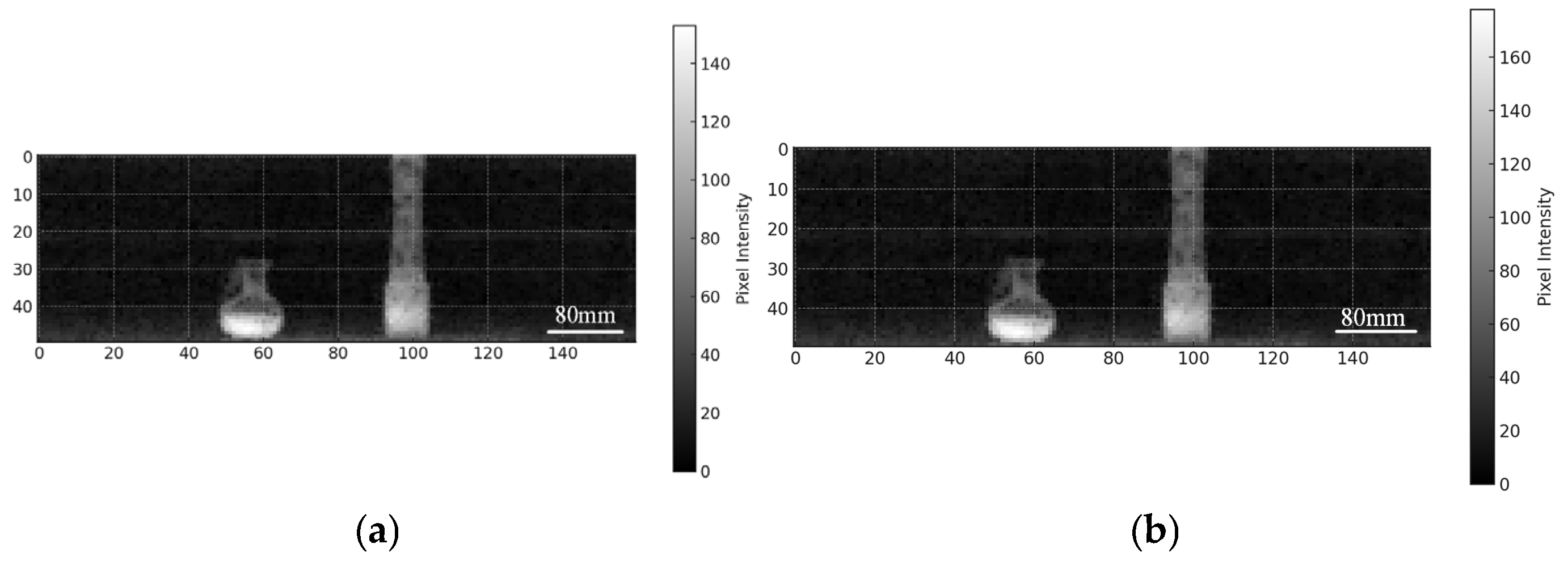
4.1. Images Acquired by Detectors with Varying Numbers of WSFs

Validation experiments were conducted using a VJ Technologies IXS1212 X-ray source (manufactured by VJ Technologies Inc., Bohemia, NY, USA) with an energy of 120 keV, and a detector featuring an active area of 40 cm × 20 cm to image a T-shaped PMMA object. The scintillator was configured with 40 and 80 WSFs, respectively. As shown in Figure 9a (imaging performance with 40 WSFs) and Figure 9b (imaging performance with 80 WSFs), increasing the fiber count substantially improved signal acquisition efficiency.
In a grayscale image, the greater the contrast, the more obvious the effective information in the image. The contrast of Figure 9a is 37.01, and that of Figure 9b is 17.17. The contrast of Figure 9b is 2.1 times that of Figure 9a, which is basically consistent with the simulation results, indicating that increasing the number of WSFs can improve the efficiency of signal acquisition.

4.2. Images Acquired by Detectors with Varying Detection Areas

Verification experiments were conducted on the scintillator detection area. Two detectors were made, each with a detection area of 40 cm × 20 cm and equipped with 80 WSFs. The energy of the radiation source was 120 keV, and imaging was performed on two explosive simulators. The left explosive was 7 cm wide and 9 cm high, while the right one was 21 cm long with a bottom diameter of 4.5 cm. Both explosive simulators were made of plastic doped with a small amount of metal. The final imaging results are shown in Figure 10. Figure 10a is the image obtained by collecting Compton scattering signals with one detector, and Figure 9b is the image obtained by collecting Compton scattering signals with two detectors.
After calculation, the contrast of Figure 10a is 18.63, and that of Figure 10b is 32.24. The contrast of Figure 10b is 1.73 times that of Figure 10a. In the simulation model, at the same detection distance, when the detection area is doubled, the collected Compton scattering signal increases by 1.68 times. The experimental results are similar to the simulation results. Both the simulation and the experiment show that increasing the detection area can effectively improve the collection efficiency of Compton scattering signals.
Flying Spot Scanning (FSS) is renowned for its high spatial resolution of 1 to 2 mm, making it an ideal choice for applications requiring detailed imaging. It offers high sensitivity, particularly excelling in detecting weak backscattered signals, which is crucial in low signal-to-noise ratio environments. FSS is also highly versatile in application, with adjustable dimensions that make it compatible with both small and large devices, as well as high- and low-energy levels. The main drawback of FSS lies in its complex data processing requirements, as image reconstruction relies on sophisticated algorithms. Despite these challenges, FSS remains a preferred option for applications demanding high-resolution and high-sensitivity imaging.
In addition to the FFS technique, there are other backscattering imaging methods, such as the lobster eye technology and the coded aperture technology, as shown in Table 3. The lobster eye technology features a wide field of view (up to 90°) and relatively simple data processing [22], as it can directly generate two-dimensional images without complex reconstruction. By assigning each microchannel to a single image pixel, it typically achieves a spatial resolution of 5 mm to 1 cm. This technology is more suitable for low-energy X-ray imaging because high-energy photons are more likely to penetrate the channel walls, which may lead to image blurring. Although the wide field of view is beneficial, it requires an inclined and compact channel structure, which may complicate the design and manufacturing. Therefore, despite its large field of view, the short distance from the object limits the field of view, and it needs to be close to the object to obtain a good Compton scattering signal, which restricts its effectiveness in imaging extremely weak signals. Thus, it is not an ideal choice for high-resolution Compton scattering imaging.
Coded aperture technology offers moderate resolution (1–10 mm) and provides a balance between performance and compactness. Its sensitivity is moderate, making it suitable for environments with stronger signals. The field of view typically ranges from 20° to 40°, offering good coverage but less than Lobster-eye technology. The primary challenge with this technology is the high data processing complexity, as it requires decoding the pattern from the mask to reconstruct the image [23]. The system is compact and does not require moving parts, which makes it suitable for security and astrophysics applications. While it offers moderate resolution and a lower sensitivity compared to FSS, its ability to work across both high and low energy levels makes it versatile in various environments.

5. Conclusions

This paper presents an optimized system strategy that integrates WSFs with scintillator detectors to enhance the detection of Compton scattering signals. By optimizing geometric parameters and material interfaces, a Compton scattering efficiency of over 25% can be attained. Through epoxy resin coupling (n = 1.5) and increasing the number of WSFs (from 40 to 100), the proposed architecture achieves a transmission efficiency from scintillator to fiber of 19.79%. Experimental validations were carried out using a 120 keV X-ray source, a T-shaped PMMA phantom, and two explosive simulators, confirming that the aforementioned optimizations have a beneficial effect on the transmission efficiency of Compton scattering signals and the signal-to-noise ratio of the images.
These research contents provide a reference for the system design that needs to utilize Compton scattering technology for high signal-to-noise ratio imaging, such as medical diagnosis, security screening, industrial inspection, astrophysics, etc. Future research directions can consider how to improve the final quantum efficiency, the performance of WSFs under other factors (temperature, bending, and arrangement method), and also explore the use of mixed scintillator materials to increase the light yield, thereby expanding the application scope of this technology.

Author Contributions

Conceptualization, B.Y.; Methodology, B.Y.; Software, B.Y. and Z.Y.; Validation, B.Y.; Formal analysis, B.M.; Investigation, X.W.; Writing—original draft, B.Y.; Writing—review & editing, X.W.; Visualization, J.X.; Supervision, C.Y.; Funding acquisition, H.L. All authors have read and agreed to the published version of the manuscript.

Funding

The National Key Research and Development Program of China (2023YFA1608400); The Foundation of Science and Technology on Near-Surface Detection Laboratory (6142414220607).

Institutional Review Board Statement

Not applicable.

Informed Consent Statement

Not applicable.

Data Availability Statement

Data are contained within the article.

Conflicts of Interest

The authors declare no conflict of interest.

References

  1. Moore, M.E.; Mozhayev, A.V.; Wittman, R.S.; Mace, E.K. Configuration and Impurity Quantification of AmLi Sources Using Radiography and Gamma Spectroscopy. Nucl. Instrum. Methods Phys. Res. Sect. A Accel. Spectrom. Detect. Assoc. Equip. 2021, 990, 164987. [Google Scholar] [CrossRef]
  2. Balogun, F.A.; Cruvinel, P.E. Compton Scattering Tomography in Soil Compaction Study. Nucl. Instrum. Methods Phys. Res. Sect. A: Accel. Spectrom. Detect. Assoc. Equip. 2003, 505, 502–507. [Google Scholar] [CrossRef]
  3. Huang, S.; Wang, X.; Chen, Y.; Xu, J.; Tang, T.; Mu, B. Modeling and quantitative analysis of X-ray transmission and backscatter imaging aimed at security inspection. Opt. Express 2019, 27, 337–349. [Google Scholar] [CrossRef]
  4. Depaola, G.O. New Monte Carlo Method for Compton and Rayleigh Scattering by Polarized Gamma Rays. Nucl. Instrum. Methods Phys. Res. Sect. A Accel. Spectrom. Detect. Assoc. Equip. 2003, 512, 619–630. [Google Scholar] [CrossRef]
  5. Xu, J.; Wang, X.; Chen, Y.; Mu, B. Compton Scattering Tomography with an Annular Detector for Inspecting Density Variations: A Monte Carlo Simulation in GEANT4. Nucl. Instrum. Methods Phys. Res. Sect. B Beam Interact. Mater. At. 2019, 443, 57–61. [Google Scholar] [CrossRef]
  6. Hamzawy, A. Compton Scattering I: Angular Distribution and Polarization Degree. Radiat. Phys. Chem. 2016, 119, 103–108. [Google Scholar] [CrossRef]
  7. Vetter, K.; Burks, M.; Cork, C.; Cunningham, M.; Chivers, D.; Hull, E.; Krings, T.; Manini, H.; Mihailescu, L.; Nelson, K.; et al. High-Sensitivity Compton Imaging with Position-Sensitive Si and Ge Detectors. Nucl. Instrum. Methods Phys. Res. Sect. A Accel. Spectrom. Detect. Assoc. Equip. 2007, 579, 363–366. [Google Scholar] [CrossRef]
  8. Guckes, A.; Green, J.A.; Tinsley, J.; Baker, S.; Schwellenbach, D. Impulse Response Measurements of Fast Scintillator-Based Current Mode Detectors. Nucl. Instrum. Methods Phys. Res. Sect. A Accel. Spectrom. Detect. Assoc. Equip. 2020, 982, 164579. [Google Scholar] [CrossRef]
  9. Ghal-Eh, N.; Koohi-Fayegh, R. A Sensitivity Analysis Approach to Optical Parameters of Scintillation Detectors. J. Lumin. 2008, 128, 11–14. [Google Scholar] [CrossRef]
  10. Gao, Y.; Cansizoglu, H.; Polat, K.G.; Ghandiparsi, S.; Kaya, A.; Mamtaz, H.H.; Mayet, A.S.; Wang, Y.; Zhang, X.; Yamada, T.; et al. Photon-Trapping Microstructures Enable High-Speed High-Efficiency Silicon Photodiodes. Nat. Photonics 2017, 11, 301–308. [Google Scholar] [CrossRef]
  11. Gallacher, D.; Leonhardt, A.; Benmansour, H.; Ellingwood, E.; Hars, Q.; Kuźniak, M.; Anstey, J.; Bondzior, B.; Boulay, M.G.; Cai, B.; et al. Development and Characterization of a Slow Wavelength Shifting Coating for Background Rejection in Liquid Argon Detectors. Nucl. Instrum. Methods Phys. Res. Sect. A Accel. Spectrom. Detect. Assoc. Equip. 2022, 1034, 166683. [Google Scholar] [CrossRef]
  12. Lin, Z.; Hautefeuille, B.; Jung, S.H.; Moon, J.; Park, J.G. The Design of a Scintillation System Based on SiPMs Integrated with Gain Correction Functionality. Nucl. Eng. Technol. 2020, 52, 164–169. [Google Scholar] [CrossRef]
  13. Nakamura, T.; Kawasaki, T.; Hosoya, T.; Toh, K.; Oikawa, K.; Sakasai, K.; Ebine, M.; Birumachi, A.; Soyama, K.; Katagiri, M. A Large-Area Two-Dimensional Scintillator Detector with a Wavelength-Shifting Fibre Readout for a Time-of-Flight Single-Crystal Neutron Diffractometer. Nucl. Instrum. Methods Phys. Res. Sect. A Accel. Spectrom. Detect. Assoc. Equip. 2012, 686, 64–70. [Google Scholar] [CrossRef]
  14. Pahlka, B.; Elpers, G.; Huang, J.; Lang, K.; Proga, M. Spectral Characterization and Modeling of Wavelength-Shifting Fibers. arXiv 2019, arXiv:1911.03790. [Google Scholar]
  15. Duan, W.; Yan, J.; Zhang, D.; Liu, H.; Liu, Y. Performance Evaluation of Gamma-Ray Detector Comprising Monolithic NaI (Tl) Scintillator and SiPM Array. In Proceedings of the 2024 IEEE Nuclear Science Symposium (NSS), Medical Imaging Conference (MIC) and Room Temperature Semiconductor Detector Conference (RTSD), Tampa, FL, USA, 27 October–1 November 2024; p. 1. [Google Scholar] [CrossRef]
  16. Britvich, G.I.; Brekhovskikh, V.V.; Semenov, V.K.; Kholodenko, S.A. The Main Characteristics of Polystyrene Scintillators Produced at the Institute of High-Energy Physics and Detectors on Their Basis. Instrum. Exp. Tech. 2015, 58, 211–220. [Google Scholar] [CrossRef]
  17. Luo, G.; Hor, Y.K.; Lu, P.-Z.; Wang, Z.-M.; Li, R.-H.; Li, M.; Li, Y.-C.; Zhan, L.; Wang, W.; Wei, Y.-H.; et al. Design Optimization of Plastic Scintillators with Wavelength-Shifting Fibers and Silicon Photomultiplier Readouts in the Top Veto Tracker of the JUNO-TAO Experiment. Nucl. Sci. Tech. 2023, 34, 99. [Google Scholar] [CrossRef]
  18. Zaitseva, N.; Rupert, B.L.; PaweŁczak, I.; Glenn, A.; Martinez, H.P.; Carman, L.; Faust, M.; Cherepy, N.; Payne, S. Plastic Scintillators with Efficient Neutron/Gamma Pulse Shape Discrimination. Nucl. Instrum. Methods Phys. Res. Sect. A Accel. Spectrom. Detect. Assoc. Equip. 2012, 668, 88–93. [Google Scholar] [CrossRef]
  19. Zong, Z.; Hull, G.; Imre, M.; Josselin, M.; Maroni, A.; Suomijärvi, T.; Daumiller, K.; Engel, R.; Mathes, H.-J.; Riegel, M.; et al. Study of Light Yield for Different Configurations of Plastic Scintillators and Wavelength Shifting Fibers. Nucl. Instrum. Methods Phys. Res. Sect. A Accel. Spectrom. Detect. Assoc. Equip. 2018, 908, 82–90. [Google Scholar] [CrossRef]
  20. Moiseev, A.A.; Deering, P.L.; Hartman, R.C.; Johnson, T.E.; Nebel, T.R.; Ormes, J.F.; Thompson, D.J. High Efficiency Plastic Scintillator Detector with Wavelength-Shifting Fiber Readout for the GLAST Large Area Telescope. Nucl. Instrum. Methods Phys. Res. Sect. A Accel. Spectrom. Detect. Assoc. Equip. 2007, 583, 372–381. [Google Scholar] [CrossRef]
  21. Riggi, S.; La Rocca, P.; Leonora, E.; Lo Presti, D.; Pappalardo, G.S.; Riggi, F.; Russo, G.V. Geant4 Simulation of Plastic Scintillator Strips with Embedded Optical Fibers for a Prototype of Tomographic System. Nucl. Instrum. Methods Phys. Res. Sect. A Accel. Spectrom. Detect. Assoc. Equip. 2010, 624, 583–590. [Google Scholar] [CrossRef]
  22. Hudec, R.; Feldman, C. Lobster Eye X-Ray Optics. In Handbook of X-Ray and Gamma-Ray Astrophysics; Bambi, C., Santangelo, A., Eds.; Springer Nature: Singapore, 2024; pp. 137–175. [Google Scholar] [CrossRef]
  23. Brady, D.J.; Marks, D.L.; MacCabe, K.P.; O’Sullivan, J.A. Coded Apertures for X-Ray Scatter Imaging. Appl. Opt. 2013, 52, 7745–7754. [Google Scholar] [CrossRef] [PubMed]
Figure 1. Schematic diagram of photon reception and transmission in the WSF scintillator system.
Photonics 12 00567 g001
Figure 2. The optical path diagram of the Compton scattering effect is shown in Figure (a), and the WSF scintillator model constructed in Geant4 is shown in Figure (b).
Photonics 12 00567 g002
Figure 3. The number of Compton scattered photons produced by PMMA under gamma-ray irradiation of different energies and the number of Compton scattered particles recorded by the scintillator are shown in (a). The number of photons produced by the scintillator after detecting Compton scattered particles of gamma rays at different energy levels is shown in (b).
Photonics 12 00567 g003
Figure 4. Compton scattering signals received by scintillators with varying detection areas at detection distances ranging from 10 cm to 50 cm were systematically investigated.
Photonics 12 00567 g004
Figure 5. Photon transmission efficiency as a function of WSF count (40–120 fibers) in a 40 cm × 20 cm scintillator under 120 keV gamma-ray irradiation was evaluated.
Photonics 12 00567 g005
Figure 6. Impact of WSFs length on transmission efficiency.
Photonics 12 00567 g006
Figure 7. Diagram of WSF scintillator detector.
Photonics 12 00567 g007
Figure 8. The Compton scattering signal detection system based on flying spot scanning is shown in Figure (a), and the fully assembled detection system is shown in Figure (b).
Photonics 12 00567 g008
Figure 9. Reconstructed images of a PMMA phantom acquired with (a) 40 and (b) 80 WSFs.
Photonics 12 00567 g009
Figure 10. Imaging was conducted on two explosive devices of different shapes. The image obtained using one scintillator is shown in (a), and the image obtained using two scintillators is shown in (b).
Photonics 12 00567 g010
Table 1. A comparison among the features of PMT with organic plastic scintillators, SiPM with inorganic scintillators and WSF scintillator method.
FeaturePMT with Organic Plastic ScintillatorsSiPM with Inorganic ScintillatorsWSF Scintillator Method
Photon TransmissionLoss due to PMT mismatchLimited by SiPM area and inefficienciesOptimized via WSF and epoxy coupling
Coupling EfficiencyLow efficiencyHigh efficiencyHigh efficiency with epoxy resin
Size and WeightLarge, bulky due to PMTSmall, Limited by the SiPM areaCompact, flexible design
Photon Yield8000~12,000 photons/MeV (e.g., Polystyrene)20,000–60,000 photons/MeV (e.g., LYSO)8000~12,000 photons/MeV (e.g., Polystyrene)
ApplicationsSecurity and nuclear detectionPortable/medical systemsHigh-res, high-sensitivity imaging
Table 2. A comparison of photon transmission efficiency between untreated interfaces and interfaces filled with epoxy resin.
WSF NumbersWSF Photon CountTransmission EfficiencyEpoxy-Resin-Enhanced WSF Photon CountTransmission Efficiency
2029941.06%41,94714.86%
3043901.55%43,27415.33%
4061452.17%45,27816.04%
5074942.65%47,16916.71%
6091563.24%51,48818.24%
7010,6123.76%53,29518.88%
8012,2314.33%54,84719.43%
9012,5074.43%55,32719.60%
10012,8664.56%55,86419.79%
Table 3. A comparison between flying spot scanning technology, lobster eye technology, and coded aperture technology.
FeatureFlying Spot Scanning (FSS)Lobster Eye TechnologyCoded Aperture Technology
Resolution1–2 mm (high resolution)5 mm to 1 cm (lower resolution)1–10 mm (moderate resolution)
SensitivityHighWeakModerate
Data ProcessingDifficult: requires the reconstruction algorithmEasy: generates two-dimensional images directlyDifficult: requires decoding of the mask pattern
System SizeBoth small and large sizes are availableSmall due to reflective surfacesSmall: compact with no moving parts
EnergyHigh-energy and low-energy compatibilityLow energyHigh-energy and low-energy compatibility
Disclaimer/Publisher’s Note: The statements, opinions and data contained in all publications are solely those of the individual author(s) and contributor(s) and not of MDPI and/or the editor(s). MDPI and/or the editor(s) disclaim responsibility for any injury to people or property resulting from any ideas, methods, instructions or products referred to in the content.

