Article

Dynamic Micro-Vibration Monitoring Based on Fractional Optical Vortex

1
Department of Physics and Electronic Science, Aba Teachers University, Wenchuan 623002, China
2
Micro-Nano Optics Laboratory, Aba Teachers University, Wenchuan 623002, China
3
Institute of Signal Processing and Transmission, Nanjing University of Posts and Telecommunications (NUPT), Nanjing 210003, China
*
Authors to whom correspondence should be addressed.
Photonics 2025, 12(6), 564; https://doi.org/10.3390/photonics12060564
Submission received: 17 April 2025 / Revised: 29 April 2025 / Accepted: 30 May 2025 / Published: 4 June 2025
(This article belongs to the Special Issue Progress in OAM Beams: Recent Innovations and Future Perspectives)

Abstract

:
In this study, we propose a novel approach for dynamic micro-vibration measurement based on an interferometric system utilizing a fractional optical vortex (FOV) beam as the reference and a Gaussian beam as the measurement path. The reflected Gaussian beam encodes the vibration information of the target, which is extracted by analyzing the rotational behavior of the petal-like interference pattern formed through coaxial interference with the FOV beam. When the topological charge (TC) of the FOV beam is less than or equal to one, a single-petal structure is generated, significantly reducing the complexity of angular tracking compared to traditional multi-petals OAM-based methods. Moreover, using a Gaussian beam as the measurement path mitigates spatial distortions during propagation, enhancing the overall robustness and accuracy. We systematically investigate the effects of TC, CCD frame rate, and interference contrast on measurement performance. Experimental results demonstrate that the proposed method achieves high angular resolution with a minimum angle deviation of 18.2 nm under optimal TC conditions. The system exhibits strong tolerance to environmental disturbances, making it well-suited for applications requiring non-contact, nanometer-scale vibration sensing, such as structural health monitoring, precision metrology, and advanced optical diagnostics.

1. Introduction

Recent advancements in optical micro-vibration measurement have significantly enhanced the precision and applicability of vibration analysis across various scientific and industrial domains. Innovations in optical sensing and computational techniques have led to the development of non-contact, high-resolution methods capable of detecting minute vibrational displacements [1].
One notable development is the application of deep learning in vision-based measurement systems. A study by Li et al. introduced a deep learning-based vision measurement method designed to accurately measure micro-vibration displacements of objects across different scenarios. This approach leverages advanced image processing algorithms to detect subtle vibrational movements, demonstrating improved accuracy over traditional methods [2]. Laser Doppler vibrometry (LDV) remains a cornerstone in optical vibration measurement, offering non-contact analysis with high sensitivity. LDV systems utilize the Doppler effect to measure velocity and displacement of vibrating surfaces, making them particularly suitable for delicate or inaccessible targets [3]. Advancements in optical accelerometers have also contributed to the field. These devices employ optical measurement techniques to achieve high-precision and electromagnetic interference-resistant acceleration measurements, proving beneficial in applications such as structural health monitoring and precision vibration isolation systems [4].
Furthermore, the integration of self-mixing interferometry has enabled the measurement of micro-harmonic vibrations with enhanced sensitivity. This technique involves the reinjection of reflected light into the laser cavity, allowing for the detection of minute vibrational changes through modulation of the laser output [5,6,7]. In summary, the field of optical micro-vibration measurement has witnessed substantial progress through the incorporation of advanced optical sensing technologies and computational methods. These developments have expanded the capabilities of vibration analysis, enabling more precise and versatile applications across various sectors.
Optical vortices (OVs) carrying orbital angular momentum (OAM) offer several advantages in micro vibration measurement [8,9]. The integration of vortex beams into micro-vibration measurement has garnered significant attention in recent research, offering novel methodologies for enhancing measurement precision and sensitivity. OAM beams, characterized by their helical phase fronts and the ability to carry quantized angular momentum, present unique advantages in detecting and analyzing micro vibrations [10].
In our previous work [11], we introduced a dynamic micro-vibration measurement technique leveraging OV. Our approach utilizes the rotational Doppler effect inherent in OV beams to detect micro-vibrations with high sensitivity. The study demonstrated that variations in the frequency shift of the reflected OV beam correlate directly with the amplitude and frequency of the micro-vibrations, enabling precise measurements. This method underscores the potential of OV beams in enhancing the detection capabilities for micro-vibration analysis. In the realm of beam characterization, Grunwald and Bock proposed a technique involving polar mapping and Fourier transform to analyze OV beams [12]. This method facilitates the detailed examination of beam profiles, which is crucial for applications requiring precise beam manipulation, including micro-vibration measurements. Furthermore, Zhang et al. developed an all-fiber laser system capable of generating pulsed polarized vortex beams [13]. This innovation offers a compact and efficient source of OV beams, which can be instrumental in micro-vibration measurement setups where space and system integration are critical considerations.
These advancements collectively highlight the emerging role of vortex beams in micro-vibration measurement research. The unique properties of OAM beams, such as their helical phase structure and angular momentum characteristics, provide new avenues for developing high-precision measurement techniques. Continued exploration in this field is poised to yield further innovations, enhancing the capabilities and applications of micro-vibration measurement technologies.
Despite the promising capabilities of OV beams in micro-vibration measurement, several inherent limitations hinder their effectiveness. Firstly, the petal-shaped interference patterns generated by the superposition of OV and Gaussian beams often exhibit morphological similarities, especially when employing low topological charges (TCs). This resemblance complicates the accurate determination of rotation angles, thereby affecting the precision of vibration measurements. Secondly, OV beams are particularly susceptible to distortions arising from environmental factors such as atmospheric turbulence, optical misalignments, and scattering. These distortions can degrade the beam quality, leading to inaccuracies in the measurement process. Addressing these challenges is crucial for enhancing the reliability and accuracy of OV-based micro-vibration measurement systems.
To address these limitations, the concept of fractional optical vortex (FOV) beams has emerged. Unlike integer optical vortex (OV) beams, fractional optical vortex (FOV) beams carry non-integer topological charges, resulting in asymmetric intensity distributions characterized by distinct radial dark regions [14,15]. These unique intensity profiles have demonstrated advantages in applications such as optical communication [16,17], optical tweezers [18,19], and optical displays [20,21]. Despite these advancements, the potential of FOV beams in optical sensing, particularly in micro-vibration measurement, remains underexplored. The non-uniform intensity characteristics of FOV beams could offer novel pathways to enhance sensitivity and robustness in micro-vibration detection systems. Recent studies have begun to investigate the application of orbital angular momentum (OAM) beams in vibration sensing, demonstrating promising results. Building upon this foundation, this study aims to investigate the application of FOV beams in micro-vibration measurement, exploring their potential to overcome existing challenges and improve measurement precision.
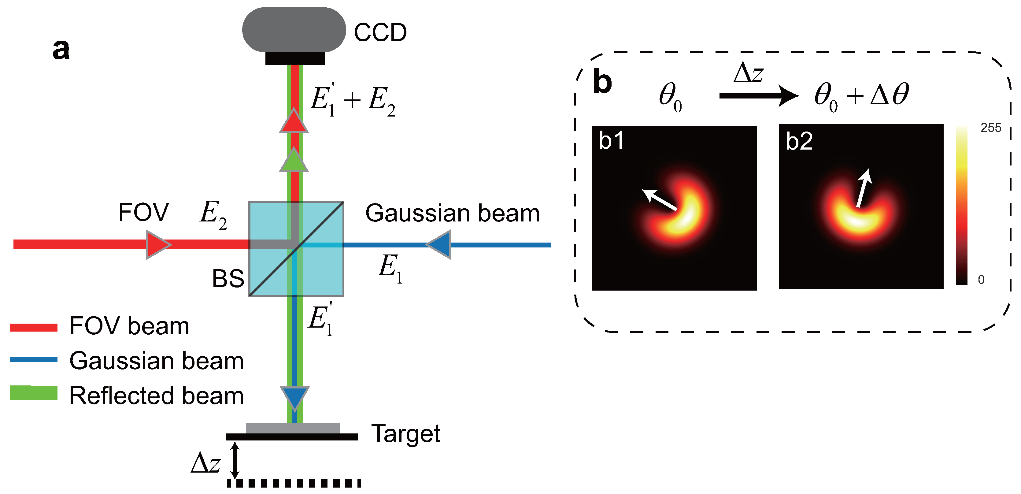
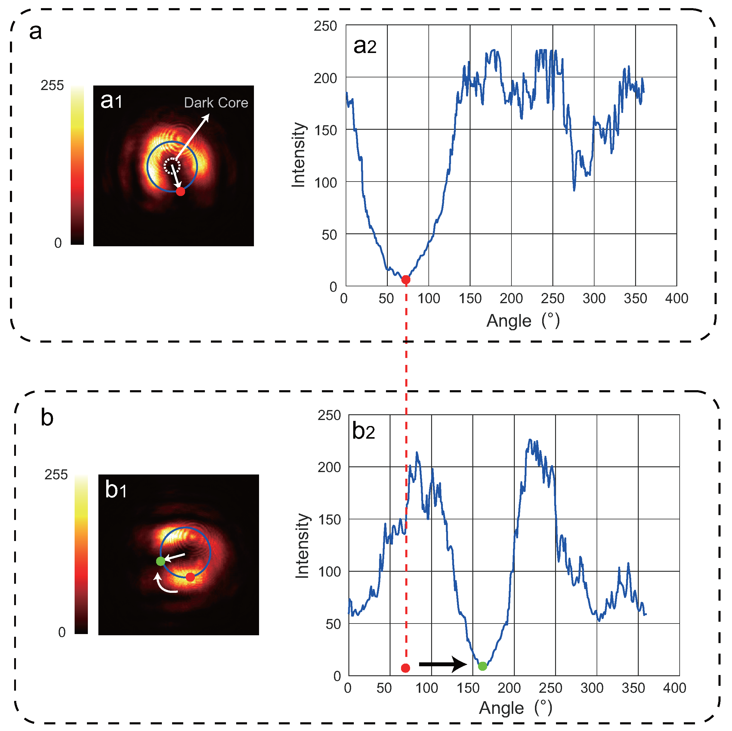
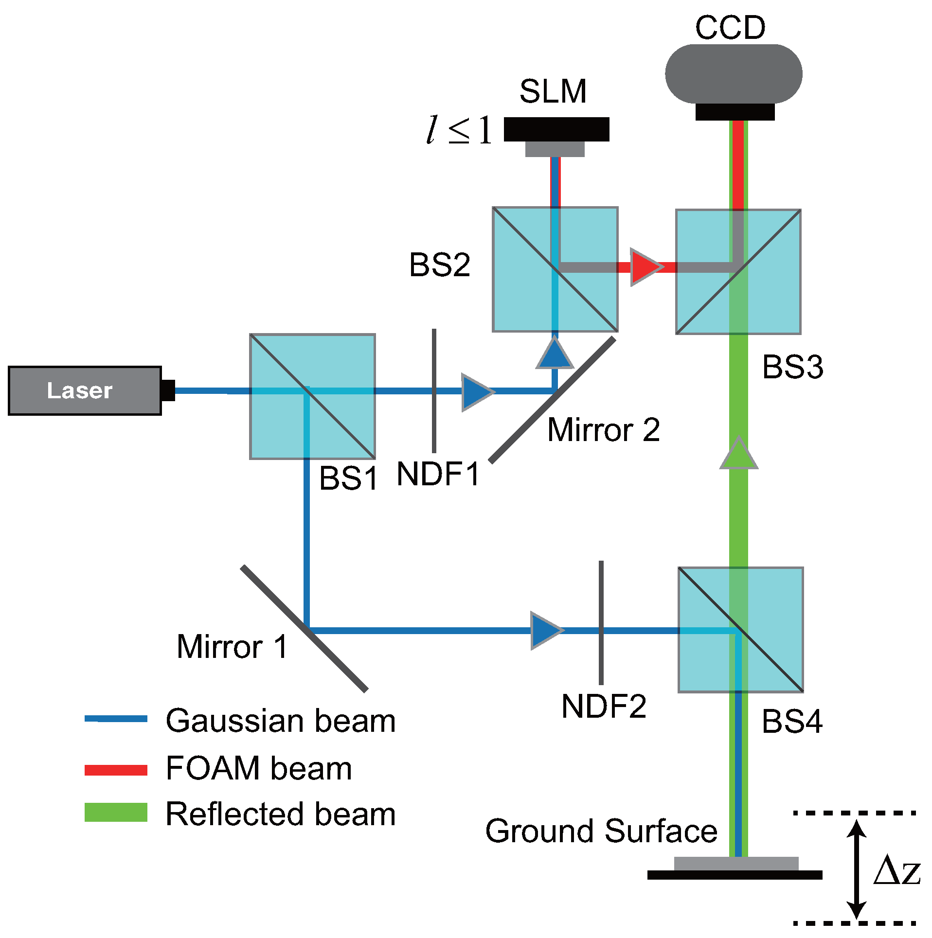
In this paper, we propose a dynamic micro-vibration monitoring method based on fractional optical vortex. In this approach, a Gaussian beam is used as the measurement beam, while a fractional optical vortex (FOV) beam serves as the reference beam. When the topological charge (TC) of the FOV beam is less than or equal to 1 ( l 1 ), a single petal-like intensity is generated, which significantly reduces the complexity of angular measurement. The measurement beam is directed onto the target, and the reflected light carries information about the vibration amplitude of the surface. When the target undergoes vibration, the single petal-like intensity in the interference pattern rotates clockwise or counterclockwise around the dark core, depending on the direction of micro-vibration.
Compared with the conventional integer-order vortex beam method [11], the proposed FOV approach offers two major advantages. First, by leveraging the non-uniform intensity distribution of the FOV beam, our method generates a single petal-like intensity. This significantly simplifies the measurement of rotational angle compared to the multiple petals produced by integer-vortex beams. Second, we employ a Gaussian beam as the measurement beam instead of the vortex beam, which reduces the spatial distortion and beam deformation during propagation. This leads to improved stability and accuracy in vibration amplitude detection.

2. Materials and Methods

2.1. The Principle of FOV-Vibration Measurement

The scheme of the principle of FOV-vibration measurement is illustrated in Figure 1, where Figure 1a,b show the optical schematic diagram, and the simulation results diagram, respectively.
In the optical schematic diagram illustrated in Figure 1a, a Gaussian beam (indicated by the blue line, measurement beam) is directed onto the vibrating target through a beam splitter (BS). The reflected signal beam (green line) is then coaxially interfered with a reference beam, represented by a fractional-order vortex (FOV) beam (red line, reference beam). The resulting interference fringes are recorded using a charge-coupled device (CCD) for subsequent analysis. The Gaussian beam can be described as
E ( r , z ) = A 0 w 0 w ( z ) exp r 2 w 2 ( z ) exp i k z i k r 2 2 R ( z ) + i ζ ( z ) ,
where E ( r , z ) denotes the complex amplitude of the beam at the radial coordinate r and axial position z. Here, A 0 is a constant representing the peak amplitude at the beam waist. w 0 is the beam waist radius, corresponding to the minimum spot size at the focal plane ( z = 0 ). The beam radius as a function of axial distance is given by w ( z ) = w 0 1 + z z R 2 , where z R = π w 0 2 / λ denotes the Rayleigh range and λ is the wavelength of the beam. The radius of curvature of the wavefront is defined as R ( z ) = z 1 + z R z 2 , and the Gouy phase shift is given by ζ ( z ) = arctan z z R . Finally, k = 2 π / λ is the wave number of the propagating beam. In our model, the Gouy phase term ζ ( z ) is omitted, as it introduces only a longitudinal phase shift that does not affect the transverse intensity distribution. Since the vibration measurement relies on detecting the angular position of petal-like intensity extrema, which are determined by the spatial interference pattern rather than the absolute phase, the Gouy phase has a negligible impact on the measurement results. Therefore, Equation (1) can be further simplified and described as
E 1 = A 1 e x p ( i ϕ 0 ) ,
where A 1 = A 0 w 0 w ( z ) exp r 2 w 2 ( z ) represents the amplitude of the Gaussian beam. ϕ 0 = ( k z + i k r 2 2 R ( z ) ) represents the initial phase of the Gaussian beam. Then, the optical field of the reflected beam ( E 1 ) from the target—encoded with the vibration information of the object—can be expressed as
E 1 = A 1 e x p ( i ϕ ) e x p ( i k 2 z ) ,
where A 1 represents the amplitude the reflected measurement beam.
The FOV beam, employed as the reference beam, can be represented by the following optical field
E 2 = A 2 e x p ( i l θ ) ,
where the A 2 ( l , r ) = r | | exp ( r 2 ) represents the amplitude the FOV beam. r represents the radius in polar coordinates. The optical field of the reference beam after passing through the BS can be expressed as
E 2 = A 2 e x p ( i l θ ) ,
The interference pattern resulting from the coaxial superposition of the measurement beam and the reference FOV beam is recorded by the CCD, and the detected intensity can be written as
I ( θ , r ) = ( E 1 + E 2 ) ( E 1 + E 2 ) * = A 1 2 + A 2 2 + 2 A 1 A 2 c o s [ l θ + ( 2 k z ϕ 0 ) ] .
where ( * ) denotes the complex conjugate of the interference field. According to Equation (6), the alternating current (AC) component, expressed as 2 A 1 A 2 c o s [ l θ + ( 2 k z ϕ ) ] , plays a central role in the formation of the petal-shaped intensity pattern. The angular period of this modulation term is given by T = 2 π / l . Consequently, the total number of intensity petals distributed over a full circular region ( 2 π ) can be determined by
n = 2 π T = | l | .
n represents the total number of intensity petals. Thus, a single petal-shaped intensity can only be observed when the magnitude of the TC is less than or equal to 1 ( l 1 ). To achieve accurate determination of the petal rotation angle, the minimum intensity point, denoted as I m i n , is identified and used as a feature to represent the brightest region of each petal. According to Equation (6), I m i n is obtained when the following phase condition is met: l θ + ( 2 k z ϕ ) = π . Thus, in the tth time, the relationship between the petal angle θ k and the axial position z t can be expressed as
θ t = 2 k z t ϕ π l .
Finally, the relationship between the vibration amplitude ( Δ z t ) and the rotation angle ( Δ θ t ) of a single petal-like intensity lobe around the dark core can be expressed as
Δ z t = z t z 0 = λ l 4 π Δ θ t ,
where z 0 signifies the initial position of the target. This indicates that the vibration amplitude of the target can be quantitatively determined by tracking the rotational displacement of an individual petal-shaped intensity feature recorded on the CCD.
The simulated results captured by the CCD are presented in Figure 1b. As shown in Figure 1b1, the angular position corresponds to the initial location of the target. After a slight displacement of the target ( Δ z ), the result is shown in Figure 1b2, where the angular position of the single petal-like intensity lobe exhibits a clockwise rotation ( Δ θ ).

2.2. The Method for Measuring the Single Petal’s Angle

Precise determination of the rotation angle of a single petal plays a key role in the measurement process. In contrast to the complex multi-lobe structures produced by integer-order vortex beams, a single-petal configuration allows for more straightforward and reliable angle extraction. The corresponding measurement method is depicted in Figure 2, where Figure 2a illustrates the CCD acquisition corresponding to the initial position of the target, accompanied by the associated angular measurement. Figure 2b depicts the CCD result after the target experiences vibration, along with the extracted rotational angle.
Step 1: The center of the dark core is determined. For integer topological charges (TCs), the intensity distribution forms a symmetric annular shape, making it straightforward to calculate the centroid. It is worth noting that the center remains invariant with respect to changes in the TC value. Therefore, the central position for fractional TCs is also assumed to be the same.
Step 2: Select the radius ( r 0 ) for intensity extraction. The radius is determined based on the intensity distribution function A ( l , r ) = r | | exp ( r 2 ) . The optimal radius is chosen as the value of r 0 = w 0 | | / 2 that maximizes this function.
Step 3: Using the previously determined center and radius, a circular path (indicated by the blue line in Figure 2a1) is defined for intensity sampling. The intensity values along this circular line are extracted and unfolded into a one-dimensional profile, as shown in Figure 2a2. The point with the minimum intensity on the circular line in Figure 2a1 (marked by a red dot) corresponds to the trough in the one-dimensional intensity distribution in Figure 2a2 (also marked by a red dot).
From Figure 2b1, it can be observed that the minimum intensity of the single petal (marked by the green dot) has rotated in the clockwise direction. The corresponding rotation angle is quantified using the method outlined in the previous steps. As shown in Figure 2b2, it is evident that the minimum intensity has shifted from its original angular position of 75 to approximately 160 . This rightward angular displacement signifies a clockwise rotation, while a leftward shift would imply counterclockwise rotation.
To quantitatively evaluate the experimental results, the average deviation (A.D.) is used, which is defined as
A . D . = 1 K i = 1 T Δ z ( t ) Δ z ( t ) ,
where Δ z t and Δ z t represent the measured and simulation vibration amplitude in the t temporal frame, respectively.

3. Results

3.1. Optical Setup

To assess the practicality of the proposed method, ground vibrations induced by mechanical tapping are monitored, with particular focus on the amplitude variation. The corresponding experimental configuration is shown in Figure 3. A diode-pumped solid-state laser (MGL-III-633-100mW) generates a laser beam with a wavelength of 633 nm. The OAM beam is produced using a spatial light modulator (SLM, Holoeye PLUTO-2-VIS), featuring 1920 × 1080 resolution, a pixel pitch of 8.0 μm, an active area of 15.36 × 8.64 mm2, and a 60 Hz refresh rate. Beam splitter 1 (BS1) divides the incoming beam into the reference and measurement paths.
In the reference path, to match the input light intensity with the operational range of the spatial light modulator (SLM), a variable neutral density filter (NDF1) is utilized for precise attenuation control. The spatial light modulator (SLM) is employed to generate fractional-order vortex beams with topological charges l 1 . Due to its programmable nature, the SLM enables precise and flexible control over the topological charge.
On the other side, NDF2 is employed to adjust and match the optical intensities of the measurement and reference beams, thereby ensuring optimal interference contrast. The measurement beam, a Gaussian beam, is directed toward the ground via beam splitter BS4, where a mirror is placed on the surface. The reflected beam, carrying the vibration information ( Δ z ) of the ground, is then combined coaxially with the FOV beam at BS3. The resulting interference pattern is captured by the CCD for subsequent analysis.

3.2. Experimental Result of Vibration Measurement

In the experiment, a heavy object was dropped from a height at a distance of 5 m from the measurement point to induce ground vibrations. The corresponding vibration amplitude observed at the surface is shown in Figure 4. To assess the effectiveness of the proposed FOV-based vibration measurement approach, a conventional seismometer based on the laser Doppler method [22] was employed as a reference for comparative analysis. From the experimental results, it can be observed that the vibration amplitudes measured by the proposed method are in good agreement with those recorded by the conventional seismometer, indicating the reliability and accuracy of the FOV-based technique. The A.D. of our proposed method is 18.2 nm.
Furthermore, the temporal response profiles obtained from both the FOV-based method and the conventional seismometer exhibit similar patterns in terms of amplitude variation and phase alignment. This consistency confirms that the proposed optical approach is capable of capturing subtle ground vibrations with high temporal fidelity. In addition, the non-contact nature of the FOV technique eliminates mechanical coupling effects and enables remote vibration detection, offering significant advantages in scenarios where traditional seismometers are impractical or invasive. These results collectively demonstrate the potential of fractional-order vortex beams as a promising tool for high-resolution, non-invasive vibration monitoring.

4. Discussion

4.1. Effect of TC on Measurement Accuracy

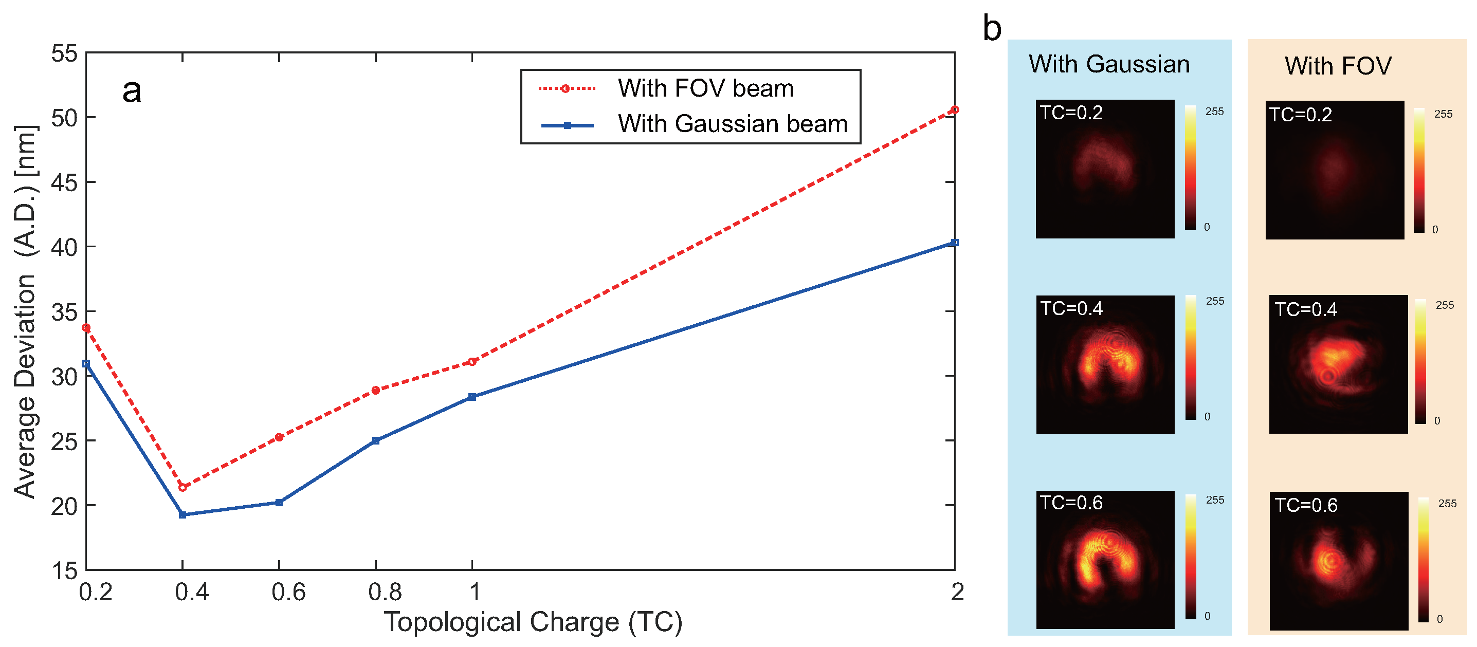
The topological charge (TC) plays a crucial role in determining the angular resolution of petal-based measurement using fractional-order vortex (FOV) beams. As the TC increases, the number of petal-like intensity lobes also increases, leading to reduced angular distinguishability for each lobe. Conversely, at very low TC values ( l 1 ), the petal becomes more pronounced and easier to track.
Figure 5 shows the experimental relationship between TC and the resulting angular deviation (A.D.) in measurement. In this experiment, the measurement beam with FOV beam and Gaussian beam are shown in Figure 5a. Compared to the Gaussian beam, the FOV beam yields slightly reduced performance, mainly because it is more vulnerable to environmental perturbations that tend to distort its spatial structure. The results also demonstrate that as TC increases from 0.2 to 2, the measurement error grows exponentially. This trend suggests that an optimal TC exists—typically around 0.5 to 1—where the petal is both distinguishable and stable for angular tracking. Thus, careful selection of TC is essential to balance pattern clarity and spatial modulation capability in FOV-based vibration sensing. However, if the TC is too small, as shown in Figure 5b, the vortex beam may not exhibit a clearly defined azimuthal structure, limiting robustness.

4.2. Effect of CCD Performance on Measurement Accuracy

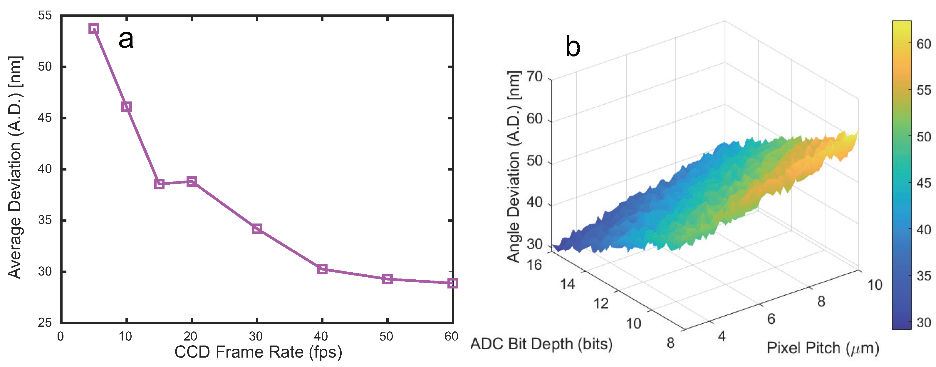
The performance of the CCD detector plays a critical role in determining the overall accuracy and robustness of the proposed petal-tracking vibration measurement system. Specifically, three major parameters—frame rate, pixel pitch, and ADC bit depth—influence the precision of angular displacement extraction, as shown in Figure 6.
The frame rate of the CCD camera plays a crucial role in determining the temporal resolution and accuracy of vibration measurements. A higher frame rate enables denser temporal sampling of the rotating petal-like patterns generated by the interference of the FOV and Gaussian beams, allowing for more precise tracking of angular changes. In contrast, a lower frame rate may result in under-sampling of the vibration-induced angular shifts, leading to aliasing, temporal ambiguity, and reduced measurement accuracy—particularly for high-frequency vibrations.
In this study, a series of experiments were conducted at varying frame rates to evaluate the effect on angle deviation (A.D.). The results show that when the CCD frame rate falls below the Nyquist sampling criterion of the vibration frequency, the extracted angular displacement becomes unreliable and prone to abrupt jumps between consecutive frames. Conversely, frame rates exceeding this threshold yield smoother and more accurate angular trajectories, with a corresponding reduction in A.D.
Figure 6a illustrates the comparison between different CCD frame rates, highlighting the substantial improvement in measurement stability and accuracy as the frame rate increases. It is also worth noting that while extremely high frame rates offer improved resolution, they may introduce additional system complexity, data volume, and synchronization challenges. Therefore, a trade-off must be considered between temporal resolution and system efficiency in practical applications.
In additon, the CCD frame rate should be at least two to three times greater than the highest significant vibration frequency to ensure robust sampling and avoid aliasing. For example, if the dominant vibration frequency is around 50 Hz, a frame rate of at least 100–150 fps should be used. For applications involving broader or higher-frequency spectra, even higher frame rates may be necessary to preserve measurement fidelity.
As shown in Figure 6b, a smaller pixel pitch enhances the spatial sampling resolution, allowing for finer localization of the intensity minima or maxima along the petal profile. This directly reduces spatial quantization errors and improves the angular resolution of the vibration measurement. In contrast, a larger pixel pitch may introduce sampling artifacts, especially when tracking subtle petal rotations corresponding to small vibration amplitudes. The ADC bit depth affects the system’s ability to resolve intensity variations within the interference pattern. A higher bit depth provides a greater number of discrete intensity levels, minimizing quantization noise and allowing for more accurate identification of the petal feature points. In practical terms, scientific-grade CCDs typically offer 12- to 16-bit ADCs, which are sufficient to capture the dynamic range needed for reliable measurement in this system.
Overall, when employing a CCD with typical scientific-grade specifications (pixel pitch 3.45–6.5 µm, ADC resolution 12–16 bits, and frame rate exceeding twice the maximum vibration frequency according to the Nyquist criterion), the influence of detector limitations on the measurement accuracy is minimized. Under such conditions, other factors such as optical distortions, environmental vibrations, and beam quality become the dominant sources of measurement uncertainty.

4.3. Effect of Intensity Contrast on Angular Measurement Accuracy

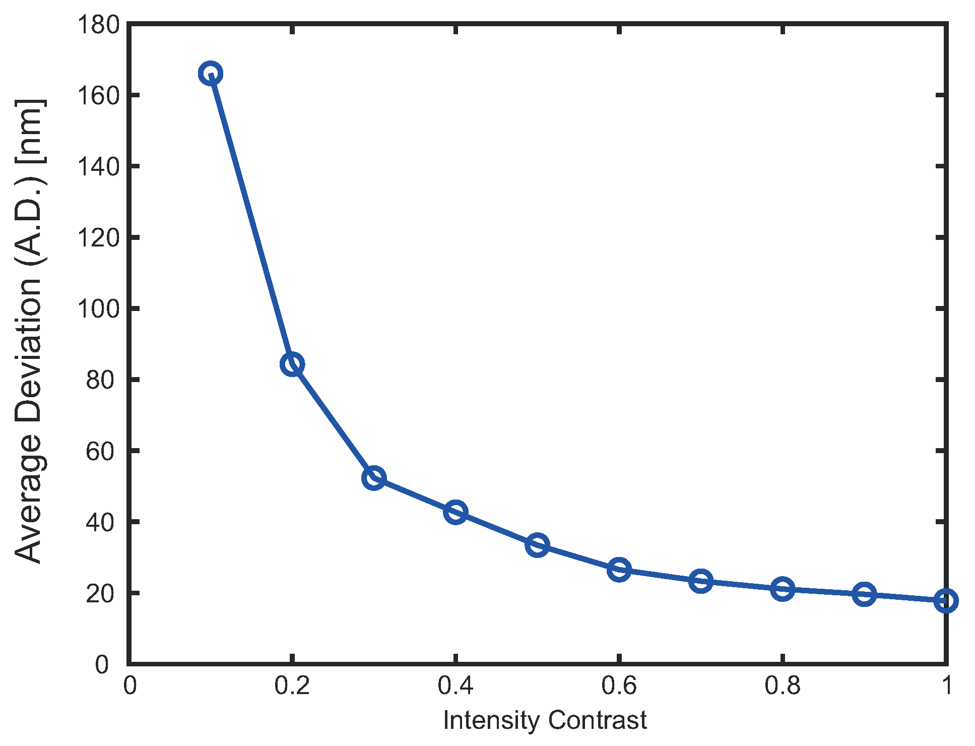
To quantitatively assess the impact of intensity contrast on angular resolution, a set of simulations was conducted, as shown in Figure 7. The contrast level—defined as the normalized difference between the bright and dark fringes of the interference pattern—was varied from 0.1 to 1.0. The resulting angle deviation (A.D.) was computed under each condition, with added random fluctuations to simulate real-world noise and beam instability.
The results clearly show that as the intensity contrast increases, the A.D. significantly decreases. In the low-contrast region (contrast < 0.3), the error rises steeply due to the difficulty in identifying clear minima or maxima along the circular sampling path. This supports the observation that under low-contrast conditions (e.g., due to beam misalignment, partial occlusion, or optical attenuation), the interference lobes become less distinguishable, causing instability in peak/trough localization.
In contrast, when the intensity contrast exceeds 0.6, the A.D. converges toward a stable minimum (18–20 nm), indicating robust feature extraction and reliable angular tracking. These results suggest that maintaining sufficient contrast—ideally greater than 0.6—is essential for achieving high-precision vibration measurements using the FOV-based approach.

5. Conclusions

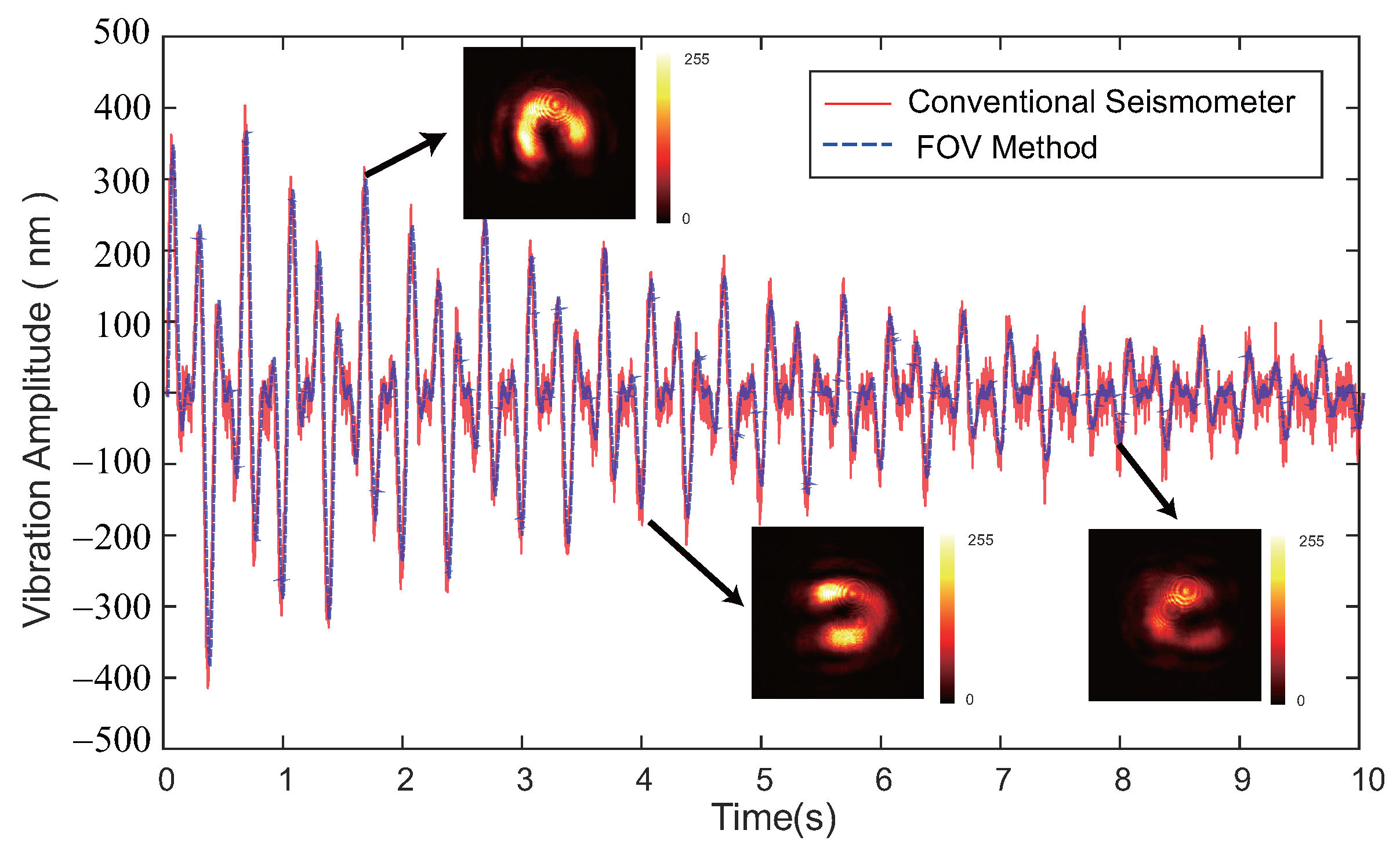
In conclusion, we proposed a dynamic micro-vibration measurement method based on the interference between a Gaussian beam and a fractional-order vortex (FOV) beam. The Gaussian beam serves as the measurement path, while the FOV beam—characterized by a non-integer topological charge—acts as the reference. Compared to conventional approaches, the proposed method simplifies the process of rotational angle measurement by reducing the structural ambiguity of the interference pattern. The impact of the TCs, CCD frame rates (fps), and the intensity contrast on the measurement accuracy are analyzed. The experimental results show that our proposed method has a higher accuracy 18.2 nm.
In future work, the proposed method could be extended to a broader range of vibration measurement scenarios, such as structural health monitoring, precision manufacturing, and biomedical sensing. Further improvements could focus on enhancing the system’s sensitivity and stability under complex environmental conditions, as well as integrating machine learning algorithms for real-time data analysis and anomaly detection. These developments would not only broaden the applicability of the technique but also promote its practical deployment in interdisciplinary fields.

Author Contributions

Conceptualization, F.Z. and J.Z.; methodology, F.Z. and L.W.; software, F.Z. and L.W.; validation, L.W.; writing—original draft preparation, F.Z.; writing—review and editing, J.Z., D.L. and S.Z.; supervision, D.L. and J.Z. All authors have read and agreed to the published version of the manuscript.

Funding

This research was funded by the National Natural Science Foundation of China (NSFC) (62375140), the Sichuan Science and Technology Program (2024YFTX0029), the Optical Technology Research Team Project at Aba Teachers University (AS-KCTD2025-02, AS-PYYB2023-02) and the Open Research Fund of National Laboratory of Solid State Microstructures under Grant (M36055).

Institutional Review Board Statement

Not applicable.

Informed Consent Statement

Not applicable.

Data Availability Statement

The data related to the paper are available from the corresponding authors upon reasonable request.

Conflicts of Interest

The authors declare no conflicts of interest.

References

  1. Chujo, T.; Sawada, H. The application of micro-vibratory phenomena of a shape-memory alloy wire to a novel vibrator. Vibration 2023, 6, 584–598. [Google Scholar] [CrossRef]
  2. Wang, X.; Li, F.; Du, Q.; Zhang, Y.; Wang, T.; Fu, G.; Lu, C. Micro-amplitude vibration measurement using vision-based magnification and tracking. Measurement 2023, 208, 112464. [Google Scholar] [CrossRef]
  3. Yuan, K.; Zhu, W. A novel general-purpose three-dimensional continuously scanning laser Doppler vibrometer system for full-field vibration measurement of a structure with a curved surface. J. Sound Vib. 2022, 540, 117274. [Google Scholar] [CrossRef]
  4. Lei, Y.J.; Li, R.J.; Zhang, L.S.; Hu, P.H.; Huang, Q.X. Optical accelerometers for detecting low-frequency micro-vibrations. Appl. Sci. 2022, 12, 3994. [Google Scholar] [CrossRef]
  5. Bhardwaj, V.K.; Maini, S. Measurement of micro-harmonic vibration from optical feedback interferometry using wavelet trend analysis. Opt. Commun. 2020, 476, 126330. [Google Scholar] [CrossRef]
  6. Jiao, X.; Zhang, J.; Li, W.; Wang, Y.; Ma, W.; Zhao, Y. Advances in spacecraft micro-vibration suppression methods. Prog. Aerosp. Sci. 2023, 138, 100898. [Google Scholar] [CrossRef]
  7. Li, L.; Wang, L.; Yuan, L.; Zheng, R.; Wu, Y.; Sui, J.; Zhong, J. Micro-vibration suppression methods and key technologies for high-precision space optical instruments. Acta Astronaut. 2021, 180, 417–428. [Google Scholar] [CrossRef]
  8. Shen, Y.; Wang, X.; Xie, Z.; Min, C.; Fu, X.; Liu, Q.; Gong, M.; Yuan, X. Optical vortices 30 years on: OAM manipulation from topological charge to multiple singularities. Light. Sci. Appl. 2019, 8, 90. [Google Scholar] [CrossRef]
  9. He, C.; Shen, Y.; Forbes, A. Towards higher-dimensional structured light. Light. Sci. Appl. 2022, 11, 205. [Google Scholar] [CrossRef]
  10. Wang, T.; Wang, H.; Lai, Y.; Xiong, H. Orbital angular momentum detection of vortex beams by#-type lines. Sci. Rep. 2025, 15, 11213. [Google Scholar]
  11. Zhu, J.; Zou, F.; Wang, L.; Zhao, S. Dynamic Micro-Vibration Measurement Based on Orbital Angular Momentum. Photonics 2023, 11, 27. [Google Scholar] [CrossRef]
  12. Grunwald, R.; Bock, M. Characterization of orbital angular momentum beams by polar mapping and Fourier Transform. Photonics 2024, 11, 296. [Google Scholar] [CrossRef]
  13. Zhang, C.; Zhang, L.; Zhang, H.; Fu, B.; Wang, J.; Qiu, M. Pulsed polarized vortex beam enabled by metafiber lasers. PhotoniX 2024, 5, 36. [Google Scholar] [CrossRef]
  14. Zhang, H.; Zeng, J.; Lu, X.; Wang, Z.; Zhao, C.; Cai, Y. Review on fractional vortex beam. Nanophotonics 2022, 11, 241–273. [Google Scholar] [CrossRef]
  15. Berry, M. Optical vortices evolving from helicoidal integer and fractional phase steps. J. Opt. A Pure Appl. Opt. 2004, 6, 259. [Google Scholar] [CrossRef]
  16. Cao, M.; Yin, Y.; Zhou, J.; Tang, J.; Cao, L.; Xia, Y.; Yin, J. Machine learning based accurate recognition of fractional optical vortex modes in atmospheric environment. Appl. Phys. Lett. 2021, 119, 141103. [Google Scholar] [CrossRef]
  17. Zhang, X.; Xia, T.; Cheng, S.; Tao, S. Free-space information transfer using the elliptic vortex beam with fractional topological charge. Opt. Commun. 2019, 431, 238–244. [Google Scholar] [CrossRef]
  18. Sun, C.; Chen, X.; Xu, H.; Liang, G. Fusion of fractional vortex pairs and their transition to integer vortex controlled by optical power. Chin. Phys. B 2025, 34, 054202. [Google Scholar] [CrossRef]
  19. Gao, B.; Wen, J.; Zhu, G.; Ye, L.; Wang, L.G. Precise measurement of trapping and manipulation properties of focused fractional vortex beams. Nanoscale 2022, 14, 3123–3130. [Google Scholar] [CrossRef]
  20. Zhu, J.; Wang, L.; Zhao, S. Security-Enhanced and High-Resolution Fractional Orbital Angular Momentum Multiplexing Holography. ACS Photonics 2024, 11, 4626–4634. [Google Scholar] [CrossRef]
  21. Xu, Z.; Wu, L.; Zhong, W.; Wu, Z.; He, Q.; Liang, Z.; Feng, G.; Wen, Y.; Chen, Y. Multiplexed Holography Using Spiral Fractional Orbital Angular Momentum. In Laser & Photonics Reviews; Wiley: Hoboken, NJ, USA, 2025; p. 2401954. [Google Scholar]
  22. Li, Y.; Dieussaert, E.; Baets, R. Miniaturization of laser doppler vibrometers—A review. Sensors 2022, 22, 4735. [Google Scholar] [CrossRef] [PubMed]
Figure 1. The scheme of the proposed method. (a) The optical schematic diagram. (b) The simulation results diagram. (b1) represents the initial rotation angle, and (b2) represents the rotation angle when the vibration reaches the dashed line in figure (a). Arrows indicate the direction of the angle corresponding to the light spot gap.
Photonics 12 00564 g001
Figure 2. (a) Angular measurement result of the single petal at the initial position of the target. The blue circular line denotes the location used for radial intensity sampling. The red dot denotes the minimum intensity. (b) The angular displacement of the petal measured at the next temporal frame. The green dot denotes the minimum intensity in the next temporal frame. Red dotted line represents the angle position in figure (b2) corresponding to the minimum intensity value in figure (a2).
Photonics 12 00564 g002
Figure 3. Experimental optical setup used for micro-vibration measurement based on fractional optical vortex beams. This setup corresponds to the principle described in Figure 1, with detailed arrangements of optical components including the beam splitter (BS), spatial light modulator (SLM), CCD camera, and vibration generation platform.
Photonics 12 00564 g003
Figure 4. Vibration monitoring results obtained using the conventional seismometer and the FOV method.
Photonics 12 00564 g004
Figure 5. (a) The average deviation of measurement results with different average deviation (A.D.), and the measurement beam with FOV beam and Gaussian beam, respectively. (b) The CCD results of different fractional TC using a Gaussian and FOV beam.
Photonics 12 00564 g005
Figure 6. (a) The average deviation of measurement results with different frame rates (fps). (b) The average deviation of measurement results with different CCD Pixel Pitch and ADC Bit Depth.
Photonics 12 00564 g006
Figure 7. The average deviation of measurement results with different intensity contrast.
Photonics 12 00564 g007
Disclaimer/Publisher’s Note: The statements, opinions and data contained in all publications are solely those of the individual author(s) and contributor(s) and not of MDPI and/or the editor(s). MDPI and/or the editor(s) disclaim responsibility for any injury to people or property resulting from any ideas, methods, instructions or products referred to in the content.

