Abstract
Micromotors play a crucial role in microsystems technology, with applications in nanoparticle propulsion, targeted drug delivery, and biosensing. Optical field propulsion, particularly optical tweezers (OTs), enables precise, noncontact control but traditionally relies on Gaussian traps, which require preprogramming and offer limited rotational control. Here, we introduce a micromotor driven by optical vortex beams, utilizing phase gradients to generate optical torque. This eliminates preprogramming and enables real-time control over rotation and positioning. Using this method, we design red blood cell (RBC)-based micromotors for targeted cellular debris collection in liquid environments. Our findings provide a versatile strategy for micro-/nano-object manipulation with potential applications in biomedicine and precision transport.
1. Introduction
Over the past decade, multifunctional micro/nanomachines have found applications in drug development and testing [1,2,3], biosensing [4,5], microfabrication [6,7], and numerous other promising domains. Micromotors, in particular, hold promise for advancing dynamic therapies [8,9]. For instance, micromotors can induce required flow fields for diversion and cargo delivery [3,10], serve as biosensors [4,11], guide neural fiber growth [12,13], and facilitate in vivo imaging [1,14]. Current propulsion methods include ultrasound [15,16], magnetic [17,18], and optical fields [19,20]. Ultrasound-driven micromotors allow for collective motion and biocompatibility but often require additional magnetic assistance and are limited to synthetic structures, posing immune response risks [21]. Magnetic micromotors, while effective, demand specific materials and pre-modifications, increasing complexity and cost [22].
Optical tweezers use highly focused laser beams to manipulate particles via momentum transfer, making them a powerful tool for optical field propulsion [23,24]. Compared to acoustic and magnetic methods, OT-driven micromotors provide superior positional accuracy and biocompatibility. Būtaitė et al. demonstrated that optical tweezers can guide locally ideal flow fields through the rotationally captured microrotors [19]. Zou et al. achieved the controlled rotation of yeast cells, proving the potential of optical tweezers for endogenous cells to act as micromotors [10]. Liu et al. designed a micromotor array based on programmable scanning optical tweezers (SOTs) to control the optical rotation of five RBCs at controlled speeds and directions, enabling selective routing and direct clearance. They successfully implemented a rotating micromotor array for selective routing and directed clearance within zebrafish [25]. Beyond that, the in vivo manipulation of neutrophils and endogenous cell nuclei has also been successfully achieved [26,27]. However, conventional OT propulsion primarily relies on SOTs, which require preprogrammed scanning trajectories, offer limited dynamic control, and exhibit weak correlations between rotation speed, scanning frequency, and optical power, making precise control challenging [28]. Beyond conventional scanning optical tweezers, other structured light-based propulsion mechanisms have also been explored. These include photothermal systems that rely on the localized heating of absorptive materials [29], and photophoretic propulsion via asymmetric light scattering on microstructured surfaces [30]. While these methods demonstrate diverse propulsion strategies, they are often constrained by fixed beam geometries, limited dynamic tunability, or material-specific interactions that complicate general biological applications.
In contrast to SOT-based systems, which rely on preprogrammed scanning trajectories and exhibit limited dynamic adaptability, our approach eliminates the need for predefined motion control by using spiral-phase optical fields that impart torque via phase gradients [31]. These fields, specifically Laguerre–Gaussian (LG) beams, enable rotation that depends solely on topological charge and photon flux, allowing the direct and continuous modulation of micromotor speed and positioning. This architecture provides real-time control, as micromotor behavior can be adjusted instantaneously by tuning the incident beam—without mechanical scanning or trajectory programming.
While our method focuses on the use of a singular LG beam, it is worth noting that the superpositions of multiple structured beams have also been employed to achieve more complex spatial modulation, such as ring-shaped traps [32] and optical vertex lattices (OVLs) [33]. In this study of RBC-based micromotors, however, we adopted to use a direct LG beam as the driving architecture. While our approach might be considered comparatively mature, it offers a favorable tradeoff between system simplicity and real-time control. More complex beam configurations, such as optical vortex lattices or spatially multiplexed modes, provide enhanced spatial patterning but often require intricate phase design and sacrifice reconfigurability. Fiber-tip vortex generators [34,35], though compact, are inherently near-field systems and thus incompatible with noninvasive in vivo applications. In contrast, our SLM-based beam shaping enables remote optical manipulation through transparent biological media without the need for physical proximity or embedded structures.
We first implemented this design using polystyrene (PS) microspheres, where a Gaussian beam provided lateral trapping and an LG beam drove stable rotation [36]. Expanding on this concept, we further designed a biologically driven micromotor using zebrafish RBCs, achieving the targeted collection of submicron cellular debris. This spiral light-driven approach offers a new technical solution for micromotor design, broadening their utility in pharmacology and biomedical engineering.
2. Methods
2.1. Design Principles and Theoretical Simulation
The LG beam is a solution to the paraxial Helmholtz equation, which describes the propagation of electromagnetic waves under the paraxial approximation. Its electric field distribution when propagating along the z-axis is given by the following [37]:
where is the peak amplitude of the field, C is the normalizing factor, expresses the beam waist, is the associated Laguerre polynomial, and denotes the Gouy phase shift. The parameter l, known as the topological charge, determines the number of helical wavefronts, whereas p represents the radial index, influencing the beam’s ring-like intensity distribution. Together, these two parameters define the order of the LG beam. Unlike a standard Gaussian beam, an LG beam possesses an annular intensity distribution and carries orbital angular momentum (OAM) due to its helical phase structure, represented by the term .
The expression in Equation (1) is presented as a theoretical reference to characterize the LG beam structure used in our system. In practice, however, LG beams are generated through wavefront manipulation using optical elements such as phase plates or spatial light modulators (SLMs) [38]. We adopt the latter approach, leveraging the programmable phase modulation capability of an SLM [39]. Specifically, to generate an LG beam of order , the phase loaded on the SLM is as follows:
where is the polar coordinate of the SLM pixels, and is the Heaviside step function used to implement the radial phase segmentation corresponding to the p-order LG mode, as described in [40]. An example hologram and the corresponding intensity distribution for an LG beam with a topological charge are shown in Figure 1a,b.
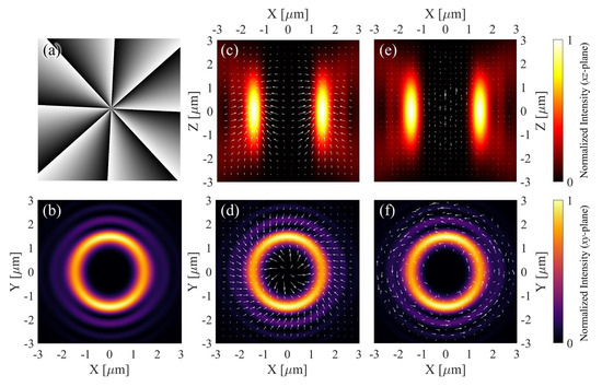
Figure 1.
(a) Hologram used to generate an LG beam with topological charge . (b) The corresponding intensity distribution in the xy-plane. (c,d) Numerically calculated optical force distribution in the xz- and xy-planes, respectively. (e,f) Numerically calculated optical torque distribution in the xz- and xy-planes, respectively. Arrow directions and relative lengths reflect simulated force and torque distributions, but absolute magnitudes are unitless and not calibrated to physical units. The top and bottom colorbars visualize relative field strength in panels (c,e) and (b,d,f), respectively.
Furthermore, to systematically investigate the transmission dynamics of LG beams and visualize their unique spatial mode characteristics, we employed a custom-made MATLAB program (Version 2024r1) with which to perform full-wave numerical simulations on the LG beam. The computed results include cross-sectional (xy-plane) and longitudinal (xz-plane) optical force and torque distributions (Figure 1c–f), providing insights into the interactions between the structured optical field and micromotors.
2.2. Experimental Setup
The experimental setup of the holographic optical tweezers system used in this study is schematically illustrated in Figure 2a. A continuous-wave 1064 nm laser (L, Maxphotonics MFSC-30W-CEA1.0, Shenzhen, China) is initially polarized by a linear polarizer (P) and then expanded using a telescope comprising two plano-convex lenses (L1 and L2), shaping the beam waist to approximately 4 mm to match the input aperture of the spatial light modulator (SLM, Holoeye PLUTO-2.1-NIR-149, Berlin, Germany). The SLM, positioned to encode holographic phase patterns, modulates the incident beam. The modulated wavefront is relayed through a 4f imaging system formed by lenses L3 and L4, ensuring that the SLM plane is optically conjugated to the back focal plane of the objective housed within an inverted microscope (Nikon Ti-2/E, Tokyo, Japan). The structured optical field is subsequently focused by a high numerical aperture (NA) objective (OBJ, Nikon CFI Plan Apo VC 60X WI NA 1.2, Tokyo, Japan), and interacts with the sample mounted on a motorized stage (SS). Finally, a digital camera (CMOS, The Imaging Source DMK 33UX249, Bremen, Germany) captures the resulting optical field for further analysis. While the native full-frame frame rate is capped at 40 fps, a reduced region-of-interest (ROI) was employed, allowing acquisition at 100 fps. This frame rate was sufficient to resolve the rotational motion of trapped microspheres.
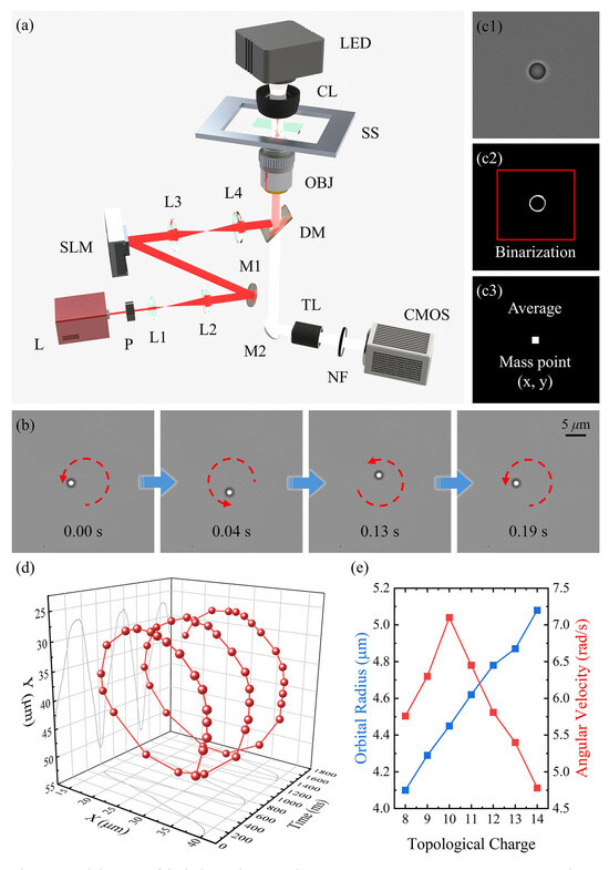
Figure 2.
(a) Schematic of the holographic optical tweezers setup. L: continuous-wave 1064 nm laser; P: linear polarizer; L1–L4: plano-convex lenses; M1, M2: mirrors; SLM: spatial-light modulator; DM: dichroic mirror; LED: diascopic illumination source; CL: condenser lens; SS: sample stage; OBJ: objective lens; TL: tube lens; NF: notch filter of 1064 nm; CMOS: camera. (b) Rotation of a PS microsphere under an LG beam. (c) Position extraction of a rotating PS microsphere using binarization: (c1) original image, (c2) binarized ring with an optimized threshold, and (c3) position determination via summation of nonzero pixels. (d) The 3D trajectory of a PS microsphere plotted in xyt-space. (e) Rotation radius and angular velocity as functions of topological charge.
2.3. Image Analysis and Particle Tracking
For trajectory analysis, binarization techniques [41,42,43] were used to extract and reconstruct the microsphere’s motion in both the x- and y-directions. Recorded video frames were first converted to grayscale using the weighted average method, transforming RGB values into grayscale intensity I(x,y) [44].
Given the uniform background illumination and high contrast between the microsphere and background, an optimal threshold was determined using the Otsu histogram optimization algorithm [45]. This produced binarized images suitable for centroid tracking (Figure 2(c2)). The centroid positions of the microsphere were computed by calculating the spatial mean of nonzero pixel coordinates (Figure 2(c3)).
2.4. Zebrafish Handling and In Vivo Imaging
Adult zebrafish were housed in a clean tank with water changes every three days. Prior to the experiment, they were anesthetized for 8 min in a 200 mg L−1 tricaine solution prepared by diluting physiological saline. Blood was collected from the caudal vein using a 10 µL micropipette. The extracted RBCs were diluted in 0.9% physiological saline and temporarily stored in a cell incubator (PH-EX, PH Biotechnology, Wuxi, China) to preserve their functionality.
For in vivo imaging, anesthetized zebrafish were positioned laterally in a custom shallow imaging chamber. The tail was gently pressed against a glass coverslip to minimize motion and bring superficial caudal blood vessels into the focal plane. The optical transparency of the tail enabled direct visualization using a high NA objective without the need for agarose embedding or deep tissue penetration. All experiments were conducted in accordance with the ethical standards of the Laboratory Animal Ethics Committee of Shandong University.
3. Results
3.1. Interaction Between the Spiral Light Field and PS Microspheres
We first validated and characterized the micromotor driving mechanism using rotational experiments with PS microspheres under optical vortex fields. In the experiment, a 2 μm PS microsphere suspended in aqueous solution was initially trapped using a 160 mW Gaussian beam, which confined the microsphere at the center of a static optical potential well. Upon switching the optical field to an LG beam, the OAM of the beam was transferred to the microsphere, inducing counterclockwise rotation about the optical axis through optomechanical interactions (Figure 2b); see Movie S1 in the Supplementary Materials).
To quantify this motion, high-speed video tracking at 100 fps was employed, revealing a full rotational cycle completed in 0.19 s with a well-defined periodic angular displacement. The microsphere trajectory was extracted using centroid tracking from binarized video frames (see Section 2 for details). Since the microsphere exhibited no displacement in the z-direction, the elapsed time was assigned as the z-axis, constructing a three-dimensional kinematic model (Figure 2d). The results confirmed that the vortex beam provided a stable rotational driving force. Further analysis of the effect of topological charge l revealed a linear increase in orbital radius with l, whereas the angular velocity exhibited a nonmonotonic trend, reaching a maximum at (Figure 2e). This peaking behavior is likely due to the balance between optical torque, trapping efficiency, and hydrodynamic drag. While increasing l enhances OAM transfer, higher l values also lead to a broader beam, reducing trapping stiffness and momentum transfer efficiency. Additionally, an increased orbital radius at high l results in greater hydrodynamic resistance and moment of inertia, slowing the rotation. This interplay causes the angular velocity to rise initially but decline beyond .
3.2. Validation of RBC Micromotors and Their Collection and Cleaning of Particles
Beyond manipulating PS microspheres, we explored the potential of RBCs as endogenous biological micromotors. During the experiment, RBCs were suspended in an anticoagulant solution and positioned using a Gaussian optical trap. Subsequently, an LG beam of was employed to induce controlled rotation. Under the influence of the structured light field, the RBC completed a full revolution around the optical axis within 0.26 s, corresponding to an angular velocity of approximately 24.2 rad/s (Figure 3a; see Movie S2 in the Supplementary Materials). This confirms the feasibility of employing structured light to drive biological micromotors.
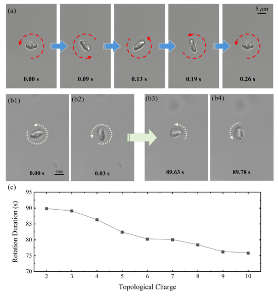
Figure 3.
(a) An RBC completes a full 360° rotation under the driving force of an LG beam with . (b) With rotation image captured at 0.00 s (b1), 0.03 s (b2), 89.63 s (b3), and 89.78 s (b4), it is shown that under continuous LG beam excitation, the RBC eventually undergoes structural deformation and ceases rotation. (c) The duration of stable rotation for RBC micromotors as a function of topological charge l. The data represent single-trial measurements selected from representative experiments demonstrating stable rotation behavior.
To assess the operational stability of the RBC micromotors, we further examined the effect of different topological charges on their longevity. As shown in Figure 3(b1–b4), the micromotor remained functional for 89.78 s before apparent deformation was observed and led to deteriorated rotating speed at (Figure 3(b4)). Notably, the operational lifespan of the micromotors decreased as the rotational speed increased, indicating an inverse relationship between longevity and angular velocity (Figure 3c).
These insights into the mechanical limits of RBC micromotors informed our next set of experiments, which focused on applying this rotational capability for functional tasks. Specifically, we explored how the controlled rotation of RBC micromotors could be utilized for microscale debris collection in biologically relevant environments. As shown in Figure 4, we developed a collection system leveraging the rotational motion of endogenous erythrocyte micromotors. To simulate a realistic scenario, a suspension of submicron-scale biological debris was prepared from zebrafish tissues, and its directed transport was achieved through LG beam manipulation.
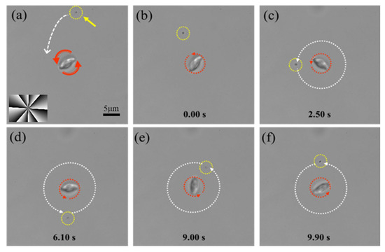
Figure 4.
(a) The positioning of an RBC micromotor near biological debris using a sample stage. (b) The RBC micromotor pulls debris toward itself through induced microfluidic flow. (c–f) The micromotor induces the circumferential motion of the debris around its rotational axis. The red dashed circle denotes the RBC’s rotation, the yellow dashed circle and arrow indicate the biological debris, and the white dashed arrows trace the trajectory of the debris.
Here, an eighth-order LG beam () was employed, driving the micromotor at a stable rotational speed of approximately 38 rad/s. This choice of reflects a balance among rotational speed, operational stability, and micromotor longevity. The rotating RBC induces a localized microfluidic vortex in the surrounding fluid via viscous coupling. This flow exerts hydrodynamic drag on nearby particles, entraining them into circular orbits around the micromotor. As demonstrated in Figure 4, by precisely controlling the micromotor’s position using a sample stage (Figure 4a,b), we gradually reduced its distance to the biological debris. When the separation reduced to approximately 15 μm, the rotation-induced microfluidic flow generated by the micromotor entrained the biological debris, pulling it toward the micromotor. Once in close proximity, the debris exhibited stable circumferential motion around the micromotor center at approximately 0.4 rad/s (Figure 4c–f), successfully demonstrating an effective mechanism for cellular debris collection. The significant difference between the RBC’s own angular velocity (~38 rad/s) and the orbital speed of the entrained debris (~0.4 rad/s) arises from the fact that only the RBC directly receives optical torque, while the debris is passively advected by the induced flow field.
3.3. Construction of Multi-RBC Micromotors and In Vivo Implementation in Zebrafish
Building upon the successful development of single RBC-based micromotors and their demonstrated capability in microparticle collection, we explored the assembly of micromotors composed of multiple RBCs. In our setup, stable micromotor assemblies were achieved with two and three RBCs, shown in Figure 5a and Figure 5b, respectively (see Movies S3 and S4 in the Supplementary Materials). Specifically, micromotors consisting of two RBCs formed a bilaterally symmetric, double-ellipsoid configuration, with the RBCs aligned side by side in a parallel configuration with their long axes oriented along the optical axis. In contrast, micromotors composed of three RBCs self-organized into a trimeric, planar structure, forming an approximately equilateral triangular arrangement, with each RBC positioned at ~120° angles relative to the others.
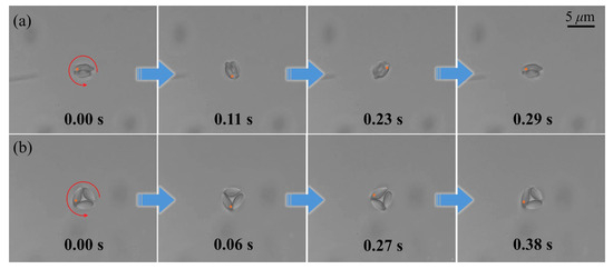
Figure 5.
(a) Rotation of the micromotor constructed of two RBCs. (b) Rotation of the micromotor constructed of three RBCs. Orange point markers are added to consistently indicate the same RBC across panels, facilitating visualization of its rotation.
Under identical laser power and topological charge conditions, the two- and three-RBC micromotors completed full 360° rotations within 0.29 s and 0.38 s, respectively. Quantitative analysis revealed an inverse correlation between RBC quantity and rotational velocity, suggesting that hydrodynamic damping effects play a significant role in multicellular micromotor architectures. Moreover, attempts to assemble micromotors with more than three RBCs proved challenging, likely due to increased hydrodynamic interactions and structural instability, which hindered stable rotational motion.
To assess the hydrodynamic feasibility of such configurations, finite-element simulations were conducted using COMSOL Multiphysics (Version 6.1) for micromotors composed of different numbers of RBCs, as shown in Figure 6a–c. The results indicated that while both single- and multi-RBC micromotors generated vortex flow fields in their immediate surroundings, the distribution patterns varied with RBC quantity. Due to simulation constraints, all velocity values were normalized for analysis. Based on the COMSOL simulation data, we analyzed the fluid velocity distribution within a 9 μm radius circular region centered on the micromotor (white dashed contours in Figure 6a–c). By performing equidistant angular sampling at 40 discrete positions, we constructed velocity distribution polar charts (Figure 6d) and summarized the data using boxplots of normalized flow velocity for different RBC configurations (Figure 6e). The results revealed that with an increasing number of RBCs, the axial velocity distribution became more uniform, reducing local fluctuations. In terms of radial distribution, while the velocity at the RBC surface remained constant at the normalized value of one, and the peak flow velocity increased at intermediate distances from the micromotor. This suggests that multi-RBC micromotors not only enhance overall flow velocity but also promote a more stable and evenly distributed hydrodynamic field.
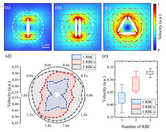
Figure 6.
Flow field simulation using the finite-element method in COMSOL for micromotors composed of (a) a single RBC, (b) two RBCs, and (c) three RBCs. (d) Polar chart of flow velocity distribution at a fixed radial distance of 9 μm for different micromotor configurations. (e) Boxplot showing the distribution of flow velocities generated by micromotors composed of different numbers of RBCs. The central line indicates the median, box edges represent the 25th and 75th percentiles, and whiskers denote the full range excluding outliers.
Following the mechanical stability validation of the multicellular micromotor, in situ assembly experiments were systematically conducted within the caudal vasculature of anesthetized zebrafish (Figure 7a). By modulating circulatory dynamics to optimize cellular capture conditions, a rotational micromotor system composed of two endogenous RBCs was successfully assembled using LG beam trapping. This biohybrid system demonstrated stable periodic motion, completing a full 360° rotational cycle within 0.48 s (Figure 7b).
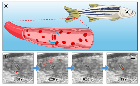
Figure 7.
(a) Schematic illustration of a two-RBC micromotor assembled within the vasculature of a zebrafish. (b) Sequential images capturing a full 360° rotation of the micromotor within the zebrafish blood vessels. Orange point markers highlight the same RBC across sequential frames to aid in tracking the rotational motion. An arrow in the second panel of (b) indicates the direction of blood flow for reference.
4. Discussion
In this study, we successfully developed a vortex light-driven micromotor system based on the precise manipulation of optical orbital angular momentum. By leveraging an LG beam, we first validated the rotational control of micron-scale PS particles, laying the foundation for constructing endogenous micromotors using RBCs. These biologically derived micromotors demonstrated the effective collection and removal of submicron-scale biological debris, highlighting their potential for biomedical applications.
To enhance the operational durability and functional versatility of RBC micromotors, we systematically investigated their longevity under different rotational speeds and further extended their capabilities by assembling multicellular micromotor clusters.
Specifically, our results show that there is an inverse relationship between rotation longevity and angular velocity. This reduced operational lifespan is influenced not only by optical intensity but also by the rotational dynamics induced by the LG beam. While a higher topological charge increases the optical torque applied to the RBCs, enabling faster rotation, the resulting mechanical stress may also contribute to membrane deformation and eventual micromotor degradation. At higher angular velocities, increased shear forces and membrane strain can accelerate structural fatigue, reducing the operational lifespan. Additionally, rapid rotation may enhance fluid interactions, leading to asymmetric deformation or increased drag forces, further compromising stability. Moreover, while photothermal effects are a consideration in optical trapping of biological specimens [46], particularly with infrared illumination, studies have shown that 1064 nm laser light induces less photothermal damage to RBCs, especially concerning membrane elasticity [47]. In our system, the use of LG beams further mitigates energy concentration due to their inherently larger focal area, resulting in lower power density compared to Gaussian beams at the same total power. To further evaluate the damage mechanism, we conducted control experiments using Gaussian traps under matched power and exposure conditions. While the LG beams rotated the RBCs for durations typically below 90 s, the RBCs trapped and exposed to Gaussian beams for the same period were still subsequently rotatable under LG illumination (see Movie S5 in Supplementary Materials). This suggests that the dominant source of damage is not photothermal, but rather the mechanical stress induced by prolonged rotation.
This evidence reinforces the notion that vortex beam-driven rotation is primarily limited by mechanical fatigue rather than thermal degradation, suggesting that micromotor longevity is not solely dictated by optical power but also by rotational speed. Thus, achieving an optimal balance between driving force and mechanical endurance is crucial for sustaining prolonged operation.
Through hydrodynamic analysis and COMSOL simulations, we revealed that increasing the RBC quantity not only modulates the rotational velocity but also stabilizes the surrounding flow field, thereby improving the micromotor performance. Moreover, we successfully engineered and operated two-RBC micromotors in vivo within zebrafish vasculature, demonstrating stable periodic motion under physiological conditions. To the best of our knowledge, this work represents the first demonstration of in vivo cell rotation using vortex beams.
Compared to conventional Gaussian optical tweezer-based micromotors, our vortex light-driven approach enables enhanced control over rotational dynamics, allowing for more precise manipulation and expanded functionality. The ability to assemble and operate multicellular micromotors in live biological environments marks a significant step toward practical applications in targeted drug delivery, microfluidic actuation, and cellular debris clearance. Beyond advancing our understanding of optical manipulation in biological systems, this approach enables the practical implementation of biohybrid micromotors for the future development of biohybrid microrobotic technologies.
In light of recent developments in optical micromotor technologies, our approach offers a distinct balance of functionality and implementation. Systems based on thermal convection [29] or photophoretic propulsion [30] often depend on specific material properties or require localized heating, which can introduce limitations in biocompatibility and control resolution. Beam-multiplexing strategies for generating complex optical fields [32,33] can enhance spatial patterning but typically suffer from reduced flexibility due to the complexity of their generation algorithms. Fiber-based vortex beam generators [34,35], while compact, are inherently limited to near-field applications and are thus unsuitable for noninvasive in vivo operation. In contrast, our far-field, SLM-driven LG beam approach enables real-time torque control, dynamic beam reconfiguration, and remote operation through transparent biological tissue. Moreover, the demonstrated use of vortex beams to rotate cells in vivo, as well as the ability to assemble multicellular micromotor units, positions this work as a unique contribution to the field of optical micromanipulation.
Supplementary Materials
The following supporting information can be downloaded at: https://www.mdpi.com/article/10.3390/photonics12060531/s1, Movie S1: Rotation of a PS microsphere under an LG beam; Movie S2: Rotation of the RBC micromotor under an LG beam; Movie S3: Rotation of the micromotor constructed of two RBCs; Movie S4: Rotation of the RBC micromotor under an LG beam within the zebrafish blood vessels. Movie S5: Control experiments using Gaussian traps under matched power to further evaluate the damage mechanism.
Author Contributions
Conceptualization, J.Z. and J.-L.W.; methodology, J.-L.W.; software, Z.Q. and J.-L.W.; validation, K.W., Y.C. and Z.Q.; formal analysis, K.W.; investigation, Z.Q. and Y.C.; data curation, K.W.; writing—original draft preparation, K.W. and Z.Q.; writing—review and editing, J.-L.W., C.F. and T.W.; visualization, K.W. and J.-L.W.; supervision, X.Z. and J.Z.; project administration, J.-L.W.; funding acquisition, X.Z. All authors have read and agreed to the published version of the manuscript.
Funding
This research was funded by the National Natural Science Foundation of China (52275154, 62305188), the Qilu Young Scholarship of Shandong University, High-level Talent Research Start-up Project Funding of Henan Academy of Sciences (No. 251820021), and the National Key Research and Development Program of China (No. 2022YFE0199800).
Institutional Review Board Statement
The animal study protocol was approved by the Ethics Committee for Animal Research of School of Life Science of Shandong University (protocol code SYDWLL-2025-094 and date of approval: 9 April 2025).
Informed Consent Statement
Not applicable.
Data Availability Statement
The data presented in this study are available on request from the corresponding author.
Conflicts of Interest
The authors declare no conflicts of interest.
Abbreviations
The following abbreviations are used in this manuscript:
| OTs | optical tweezers |
| RBC | red blood cell |
| SOTs | scanning optical tweezers |
| PS | polystyrene |
| LG | Laguerre–Gaussian |
| OAM | orbital angular momentum |
| SLMs | spatial light modulators |
| NA | numerical aperture |
References
- Ou, J.; Liu, K.; Jiang, J.; Wilson, D.A.; Liu, L.; Wang, F.; Wang, S.; Tu, Y.; Peng, F. Micro-/nanomotors toward biomedical applications: The recent progress in biocompatibility. Small 2020, 16, 1906184. [Google Scholar] [CrossRef] [PubMed]
- Liu, S.; Gao, C.; Peng, F. Micro/nanomotors in regenerative medicine. Mater. Today Adv. 2022, 16, 100281. [Google Scholar] [CrossRef]
- Srivastava, S.K.; Clergeaud, G.; Andresen, T.L.; Boisen, A. Micromotors for drug delivery in vivo: The road ahead. Adv. Drug Deliv. Rev. 2019, 138, 41–55. [Google Scholar] [CrossRef] [PubMed]
- Esteban-Fernández de Ávila, B.; Gao, W.; Karshalev, E.; Zhang, L.; Wang, J. Cell-like micromotors. Acc. Chem. Res. 2018, 51, 1901–1910. [Google Scholar] [CrossRef]
- Rojas, D.; Jurado-Sánchez, B.; Escarpa, A. “Shoot and sense” Janus micromotors-based strategy for the simultaneous degradation and detection of persistent organic pollutants in food and biological samples. Anal. Chem. 2016, 88, 4153–4160. [Google Scholar] [CrossRef]
- Mehregany, M.; Tai, Y.-C. Surface micromachined mechanisms and micromotors. J. Micromech. Microeng. 1991, 1, 73. [Google Scholar] [CrossRef]
- Barbade, D.; Soni, R.; Metan, S. Micromotor Fabrication by Surface Micromachining Technique. In MEMS and Nanotechnology, Proceedings of the 2010 Annual Conference on Experimental and Applied Mechanics, Indianapolis, IN, USA, 7–10 June 2010; Springer: New York, NY, USA, 2011; Volume 2, pp. 139–146. [Google Scholar]
- Wan, M.; Li, T.; Chen, H.; Mao, C.; Shen, J. Biosafety, functionalities, and applications of biomedical micro/nanomotors. Angew. Chem. Int. Ed. 2021, 60, 13158–13176. [Google Scholar] [CrossRef]
- Gardi, G.; Ceron, S.; Wang, W.; Petersen, K.; Sitti, M. Microrobot collectives with reconfigurable morphologies, behaviors, and functions. Nat. Commun. 2022, 13, 2239. [Google Scholar] [CrossRef]
- Zou, X.; Zheng, Q.; Wu, D.; Lei, H. Controllable Cellular Micromotors Based on Optical Tweezers. Adv. Funct. Mater. 2020, 30, 2002081. [Google Scholar] [CrossRef]
- Li, Y.; Liu, X.; Xu, X.; Xin, H.; Zhang, Y.; Li, B. Red-blood-cell waveguide as a living biosensor and micromotor. Adv. Funct. Mater. 2019, 29, 1905568. [Google Scholar] [CrossRef]
- Wu, T.; Nieminen, T.A.; Mohanty, S.; Miotke, J.; Meyer, R.L.; Rubinsztein-Dunlop, H.; Berns, M.W. A photon-driven micromotor can direct nerve fibre growth. Nat. Photonics 2012, 6, 62–67. [Google Scholar] [CrossRef]
- Feng, Y.; Gao, C.; Xie, D.; Liu, L.; Chen, B.; Liu, S.; Yang, H.; Gao, Z.; Wilson, D.A.; Tu, Y. Directed Neural Stem Cells Differentiation via Signal Communication with Ni–Zn Micromotors. Adv. Mater. 2023, 35, 2301736. [Google Scholar] [CrossRef]
- Simaan, N.; Yasin, R.M.; Wang, L. Medical technologies and challenges of robot-assisted minimally invasive intervention and diagnostics. Annu. Rev. Control Robot. Auton. Syst. 2018, 1, 465–490. [Google Scholar] [CrossRef]
- Cao, H.X.; Jung, D.; Lee, H.-S.; Go, G.; Nan, M.; Choi, E.; Kim, C.-S.; Park, J.-O.; Kang, B. Micromotor manipulation using ultrasonic active traveling waves. Micromachines 2021, 12, 192. [Google Scholar] [CrossRef]
- Gao, Q.; Yang, Z.; Zhu, R.; Wang, J.; Xu, P.; Liu, J.; Chen, X.; Yan, Z.; Peng, Y.; Wang, Y. Ultrasonic steering wheels: Turning micromotors by localized acoustic microstreaming. ACS Nano 2023, 17, 4729–4739. [Google Scholar] [CrossRef]
- Wu, Z.; Li, T.; Li, J.; Gao, W.; Xu, T.; Christianson, C.; Gao, W.; Galarnyk, M.; He, Q.; Zhang, L. Turning erythrocytes into functional micromotors. Acs Nano 2014, 8, 12041–12048. [Google Scholar] [CrossRef]
- Hou, K.; Zhang, Y.; Bao, M.; Xin, C.; Wei, Z.; Lin, G.; Wang, Z. A multifunctional magnetic red blood cell-mimetic micromotor for drug delivery and image-guided therapy. ACS Appl. Mater. Interfaces 2022, 14, 3825–3837. [Google Scholar] [CrossRef]
- Būtaitė, U.G.; Gibson, G.M.; Ho, Y.-L.D.; Taverne, M.; Taylor, J.M.; Phillips, D.B. Indirect optical trapping using light driven micro-rotors for reconfigurable hydrodynamic manipulation. Nat. Commun. 2019, 10, 1215. [Google Scholar] [CrossRef]
- Metzger, N.; Mazilu, M.; Kelemen, L.; Ormos, P.; Dholakia, K. Observation and simulation of an optically driven micromotor. J. Opt. 2011, 13, 044018. [Google Scholar] [CrossRef]
- Li, J.; Esteban-Fernández de Ávila, B.; Gao, W.; Zhang, L.; Wang, J. Micro/nanorobots for biomedicine: Delivery, surgery, sensing, and detoxification. Sci. Robot. 2017, 2, eaam6431. [Google Scholar] [CrossRef]
- Wu, R.; Zhu, Y.; Cai, X.; Wu, S.; Xu, L.; Yu, T. Recent process in microrobots: From propulsion to swarming for biomedical applications. Micromachines 2022, 13, 1473. [Google Scholar] [CrossRef] [PubMed]
- Ashkin, A.; Dziedzic, J.M.; Bjorkholm, J.E.; Chu, S. Observation of a single-beam gradient force optical trap for dielectric particles. Opt. Lett. 1986, 11, 288–290. [Google Scholar] [CrossRef] [PubMed]
- Qu, Z.; Wang, K.; Feng, C.; Wu, T.; Zhang, Y.; Zhao, X.; Wang, J.-L. Optofluidic sorting of microparticles using Airy beams. Int. J. Optomechatronics 2024, 18, 2375538. [Google Scholar] [CrossRef]
- Liu, X.; Wu, H.; Wu, S.; Qin, H.; Zhang, T.; Lin, Y.; Zheng, X.; Li, B. Optically Programmable Living Microrouter in Vivo. Adv. Sci. 2023, 10, 2304103. [Google Scholar] [CrossRef]
- Liu, X.; Gao, Q.; Wu, S.; Qin, H.; Zhang, T.; Zheng, X.; Li, B. Optically Manipulated Neutrophils as Native Microcrafts In Vivo. ACS Cent. Sci. 2022, 8, 1017–1027. [Google Scholar] [CrossRef]
- Gao, Q.; Wang, W.; Li, X.; Li, Y.; Ferraro, P.; Jiao, X.; Liu, X.; Zhang, Y.; Li, B. Cell nucleus as endogenous biological micropump. Biosens. Bioelectron. 2021, 182, 113166. [Google Scholar] [CrossRef]
- Xu, X.; Yang, Y.; Chen, L.; Chen, X.; Wu, T.; Li, Y.; Liu, X.; Zhang, Y.; Li, B. Optomechanical wagon-wheel effects for bidirectional sorting of dielectric nanoparticles. Laser Photonics Rev. 2021, 15, 2000546. [Google Scholar] [CrossRef]
- Zhou, Y.; Li, S.; Gao, J.; Qin, Y.; Zhang, Y.; Zhang, Y.; Liu, Z.; Yuan, L. All-fiber rotary micromotor based on laser-induced thermal convection. Opt. Laser Technol. 2023, 165, 109639. [Google Scholar] [CrossRef]
- Zhang, Y.; Lin, S.; Liu, Z.; Zhang, Y.; Zhang, J.; Yang, J.; Yuan, L. Laser-induced rotary micromotor with high energy conversion efficiency. Photon. Res. 2020, 8, 534–538. [Google Scholar] [CrossRef]
- Courtial, J.; Padgett, M.J. Limit to the orbital angular momentum per unit energy in a light beam that can be focussed onto a small particle. Opt. Commun. 2000, 173, 269–274. [Google Scholar] [CrossRef]
- Li, X.; Dan, D.; Yu, X.; Zhou, Y.; Zhang, Y.; Gao, W.; Li, M.; Xu, X.; Yan, S.; Yao, B. Concentric ring optical traps for orbital rotation of particles. Nanophotonics 2023, 12, 4507–4517. [Google Scholar] [CrossRef] [PubMed]
- Zhu, L.; Tang, M.; Li, H.; Tai, Y.; Li, X. Optical vortex lattice: An exploitation of orbital angular momentum. Nanophotonics 2021, 10, 2487–2496. [Google Scholar] [CrossRef]
- Wu, L.; Bai, Z.; Wang, Y.; Liu, R.; Yu, J.; Ran, J.; Luo, Z.; Liu, S.; Wang, Y.; Chen, G.Y.; et al. Micromotor based on single fiber optical vortex tweezer. APL Photonics 2024, 9, 116106. [Google Scholar] [CrossRef]
- Nguyen, H.T.; Stepniewski, G.; Filipkowski, A.; Kasztelanic, R.; Pysz, D.; Le Van, H.; Stepien, R.; Klimczak, M.; Krolikowski, W.; Buczynski, R. Transmission of an optical vortex beam in antiresonant fibers generated in an all-fiber system. Opt. Express 2022, 30, 45635–45647. [Google Scholar] [CrossRef]
- Liu, S.; Fan, X.; Qu, Z.; Fang, C.; Feng, C.; Zhao, X.; Wang, J.-L. Improving the multi-functionality of optical tweezers with FPGA integration. Appl. Opt. 2023, 63, 255–262. [Google Scholar] [CrossRef]
- Yao, A.M.; Padgett, M.J. Orbital angular momentum: Origins, behavior and applications. Adv. Opt. Photon. 2011, 3, 161–204. [Google Scholar] [CrossRef]
- Curtis, J.E.; Grier, D.G. Structure of optical vortices. Phys. Rev. Lett. 2003, 90, 133901. [Google Scholar] [CrossRef]
- Qu, Z.; Liu, S.; Fan, X.; Fang, C.; Wang, J.-L.; Zhao, X. Optimized hologram generation method for real-time spontaneous manipulation. AIP Adv. 2023, 13, 095216. [Google Scholar] [CrossRef]
- Jones, P.H.; Maragò, O.M.; Volpe, G. Optical Tweezers: Principles and Applications; Cambridge University Press: Cambridge, UK, 2016. [Google Scholar]
- Liu, S.; Qu, Z.; Zhao, X.; Wang, J.-L. Fast and versatile optical force measurement with digitally modulated stimulus in holographic optical tweezers. Opt. Laser Technol. 2023, 167, 109809. [Google Scholar] [CrossRef]
- Koekoek, R. Generalizations of Laguerre polynomials. J. Math. Anal. Appl. 1990, 153, 576–590. [Google Scholar] [CrossRef]
- Izakian, Z.; Mesgari, M.S.; Weibel, R. A feature extraction based trajectory segmentation approach based on multiple movement parameters. Eng. Appl. Artif. Intell. 2020, 88, 103394. [Google Scholar] [CrossRef]
- Hsieh, J.-W.; Yu, S.-L.; Chen, Y.-S. Motion-based video retrieval by trajectory matching. IEEE Trans. Circuits Syst. Video Technol. 2006, 16, 396–409. [Google Scholar] [CrossRef]
- Ma, G.; Yue, X. An improved whale optimization algorithm based on multilevel threshold image segmentation using the Otsu method. Eng. Appl. Artif. Intell. 2022, 113, 104960. [Google Scholar] [CrossRef]
- Krasnikov, I.; Seteikin, A.; Bernhardt, I. Thermal processes in red blood cells exposed to infrared laser tweezers (λ = 1064 nm). J. Biophotonics 2011, 4, 206–212. [Google Scholar] [CrossRef]
- de Oliveira, M.A.; Moura, D.; Fontes, A.; de Araujo, R. Damage induced in red blood cells by infrared optical trapping: An evaluation based on elasticity measurements. J. Biomed. Opt. 2016, 21, 075012. [Google Scholar] [CrossRef]
Disclaimer/Publisher’s Note: The statements, opinions and data contained in all publications are solely those of the individual author(s) and contributor(s) and not of MDPI and/or the editor(s). MDPI and/or the editor(s) disclaim responsibility for any injury to people or property resulting from any ideas, methods, instructions or products referred to in the content. |
© 2025 by the authors. Licensee MDPI, Basel, Switzerland. This article is an open access article distributed under the terms and conditions of the Creative Commons Attribution (CC BY) license (https://creativecommons.org/licenses/by/4.0/).