Damage Characteristics in Glass Fiber-Reinforced Epoxy Resin Composites Under Continuous Wave and Pulsed Laser Modes

Abstract
1. Introduction
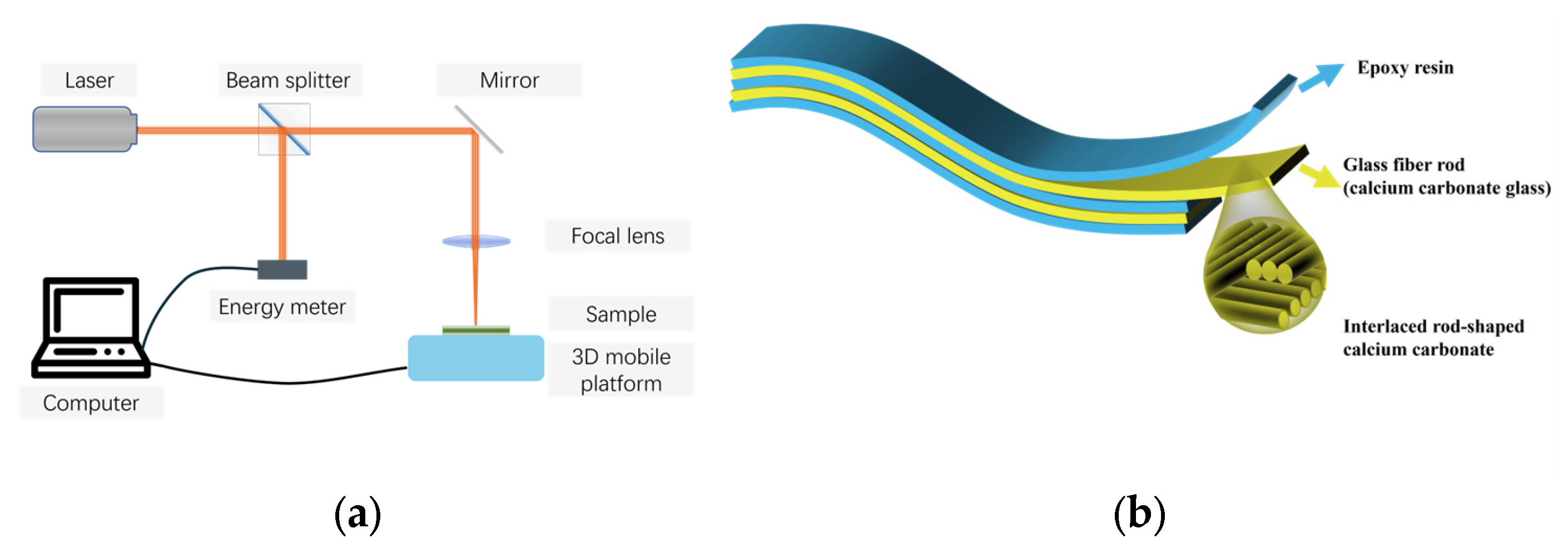
2. Experimental Setup
3. Results and Discussion
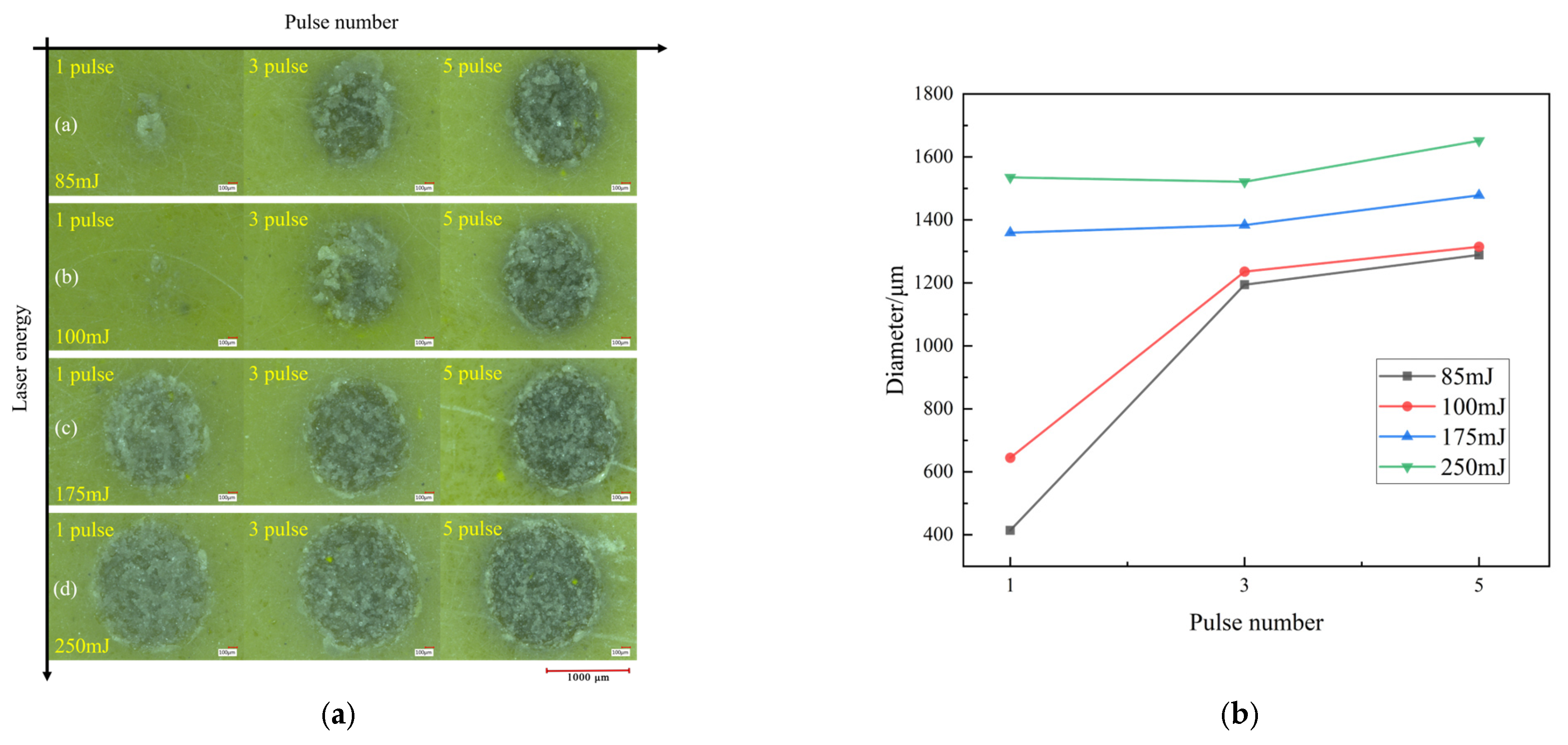
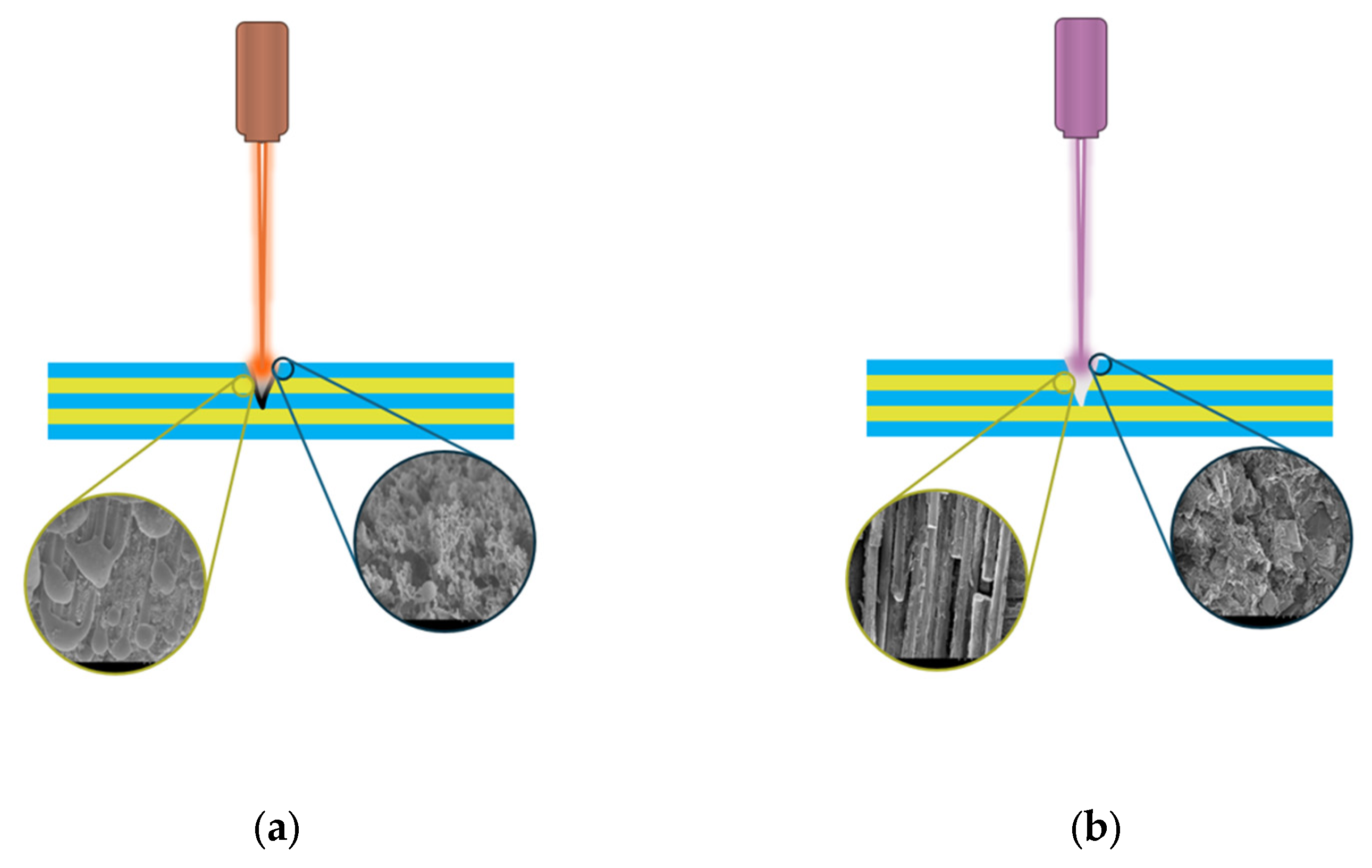
3.1. Damage Characteristics of PL
3.2. Damage Characteristics of CW
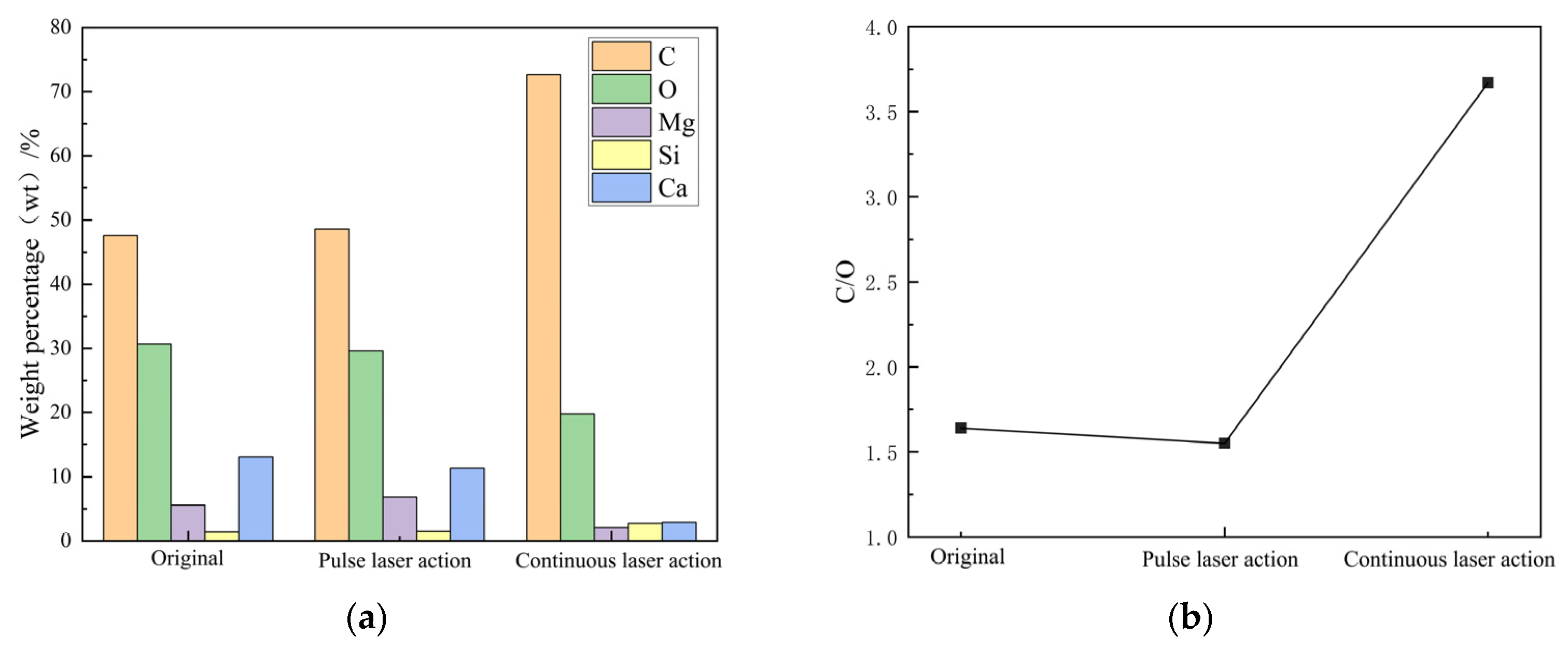
3.3. Elemental Content Analysis
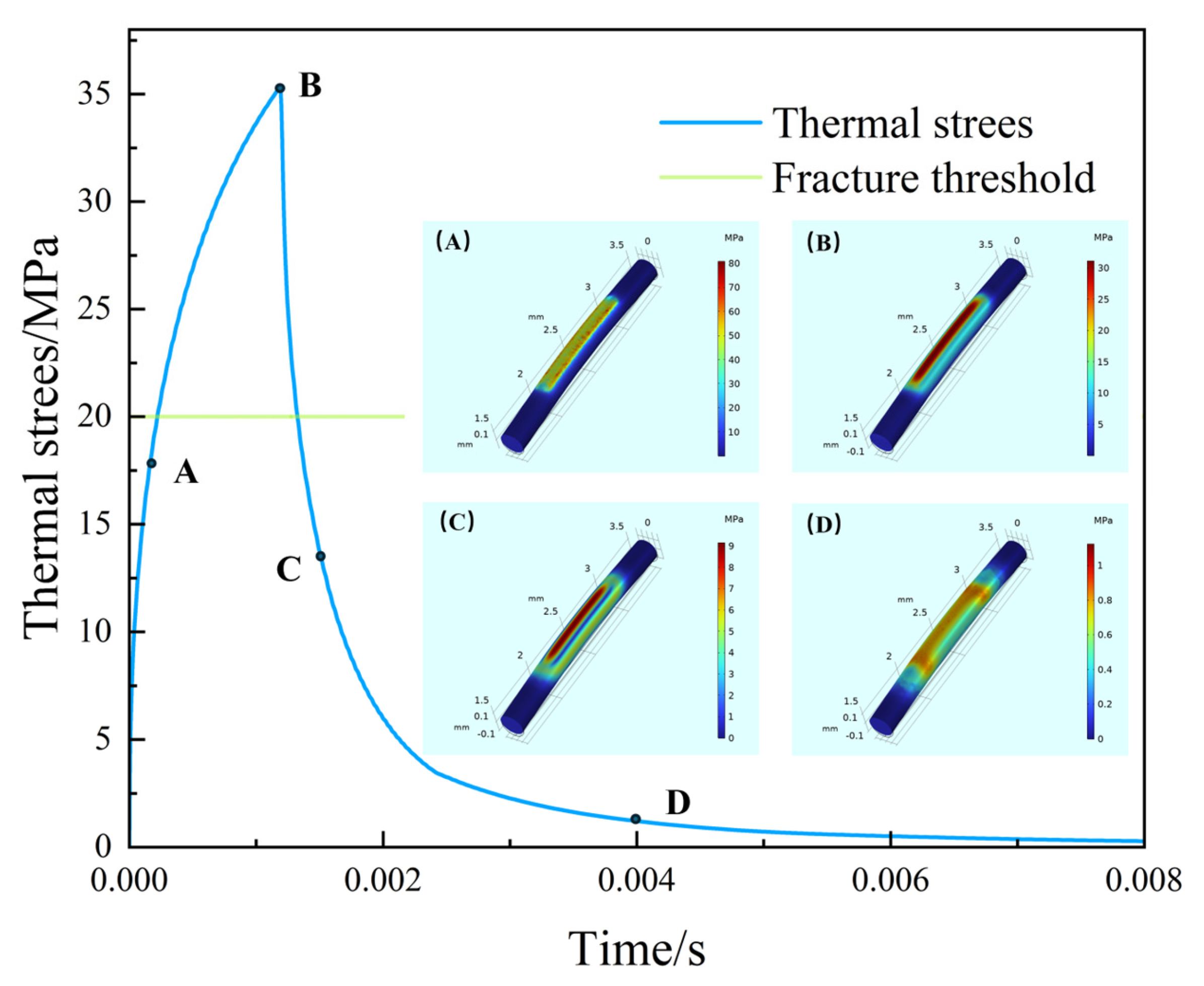
4. Theoretical Research
4.1. Thermodynamic Analysis Model
4.2. PL Effects
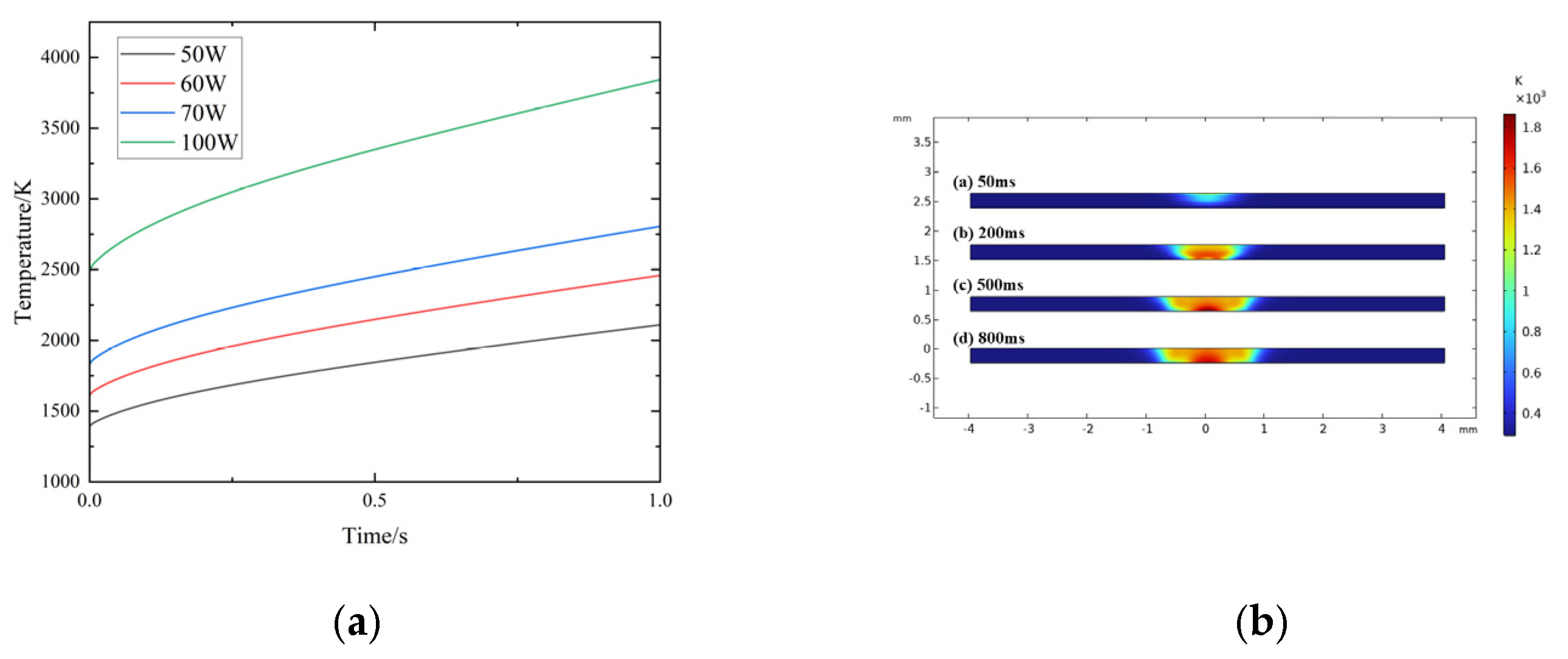
4.3. CW Effects
5. Conclusions
Author Contributions
Funding
Institutional Review Board Statement
Informed Consent Statement
Data Availability Statement
Conflicts of Interest
References
- Jones, C.E.; Norman, P.J.; Burt, G.M.; Hill, C.; Allegri, G.; Yon, J.M.; Hamerton, I.; Trask, R.S. A route to sustainable aviation: A roadmap for the realization of aircraft components with electrical and structural multifunctionality. IEEE Trans. Transp. Electrif. 2021, 7, 3032–3049. [Google Scholar] [CrossRef]
- Vigneshwaran, M.; Kumaran, M.; Revanth, K. Correlation of CFRP and AA7075 Aircraft Wing box structure using FEM. In IOP Conference Series: Materials Science and Engineering, Proceedings of the 3rd International Conference on trends in Material Science and Inventive Materials (ICTMIM 2021), Coimbatore, India, 12–13 March 2021; IOP Publishing: Bristol, UK, 2021; Volume 1126, p. 012081. [Google Scholar]
- Guo, F.; Xiao, Q.; Xiao, S.; Wang, Z. Assembly technology for aeronautical CFRP structures under the collaborative constrains of geometric shape, physical performance and service stability. Compos. Struct. 2023, 318, 117071. [Google Scholar] [CrossRef]
- Ma, X.; An, N.; Cong, Q.; Bai, J.-B.; Wu, M.; Xu, Y.; Zhou, J.; Zhang, D.; Zhang, T.; Guo, R.; et al. Design, modeling, and manufacturing of high strain composites for space deployable structures. Commun. Eng. 2024, 3, 78. [Google Scholar] [CrossRef]
- Zhang, Q.; Qin, Z.; Yan, R.; Wei, S.; Zhang, W.; Lu, S.; Jia, L. Processing technology and ballistic-resistant mechanism of shear thickening fluid/high-performance fiber-reinforced composites: A review. Compos. Struct. 2021, 266, 113806. [Google Scholar] [CrossRef]
- Odesanya, K.O.; Ahmad, R.; Jawaid, M.; Bingol, S.; Adebayo, G.O.; Wong, Y.H. Natural fibre-reinforced composite for ballistic applications: A review. J. Polym. Environ. 2021, 29, 3795–3812. [Google Scholar] [CrossRef]
- Tsirogiannis, E.C.; Daskalakis, E.; Hassan, M.H.; Omar, A.M.; Bartolo, P. Ballistic design and testing of a composite armour reinforced by CNTs suitable for armoured vehicles. Def. Technol. 2024, 32, 173–195. [Google Scholar] [CrossRef]
- Vlase, S.; Gheorghe, V.; Marin, M.; Öchsner, A. Study of structures made of composite materials used in automotive industry. Proc. Inst. Mech. Eng. Part L J. Mater. Des. Appl. 2021, 235, 2574–2587. [Google Scholar] [CrossRef]
- Lin, M.; Mei, Q. Optimization of the Vehicles Production by Using Lightweight Carbon Fibre Composite Materials. In IOP Conference Series: Earth and Environmental Science, Proceedings of the 2020 6th International Conference on Energy, Environment and Materials Science, Hulun Buir, China, 28–30 August 2020; IOP Publishing: Bristol, UK, 2020; Volume 585, p. 012195. [Google Scholar]
- Pandian, V.; Kannan, S. Processing and preparation of aerospace-grade aluminium hybrid metal matrix composite in a modified stir casting furnace integrated with mechanical supersonic vibration squeeze infiltration method. Mater. Today Commun. 2021, 26, 101732. [Google Scholar] [CrossRef]
- Pandian, V.; Kannan, S. Effect of high entropy particle on aerospace-grade aluminium composite developed through combined mechanical supersonic vibration and squeeze infiltration technique. J. Manuf. Process. 2022, 74, 383–399. [Google Scholar] [CrossRef]
- Jayakumar, S.S.; Subramaniam, I.P.; Arputharaj, B.S.; Solaiappan, S.K.; Rajendran, P.; Lee, I.E.; Madasamy, S.K.; Gnanasekaran, R.K.; Karuppasamy, A.; Raja, V. Design, control, aerodynamic performances, and structural integrity investigations of compact ducted drone with co-axial propeller for high altitude surveillance. Sci. Rep. 2024, 14, 6330. [Google Scholar] [CrossRef]
- Galatas, A.; Hassanin, H.; Zweiri, Y.; Seneviratne, L. Additive manufactured sandwich composite/ABS parts for unmanned aerial vehicle applications. Polymers 2018, 10, 1262. [Google Scholar] [CrossRef] [PubMed]
- Steinvall, O. The potential role of laser in combating UAVs: Part 2; laser as a countermeasure and weapon. In Proceedings of the Technologies for Optical Countermeasures XVIII and High-Power Lasers: Technology and Systems, Platforms, Effects V, Online, 12 September 2021; SPIE: St. Bellingham, WA, USA, 2021; Volume 11867, pp. 14–30. [Google Scholar]
- Wang, J.; Xie, W.; Yan, H.; Yu, D.; Gao, B.; Yang, F.; Liu, S.; Meng, S. Study on multi-scale ablation behavior of C/SiC composites under high-energy CW laser irradiation. J. Eur. Ceram. Soc. 2024, 44, 4524–4535. [Google Scholar] [CrossRef]
- Jia, X.S.; Luo, J.L.; Li, K.; Wang, C.; Li, Z.; Wang, M.M.; Jiang, Z.Y.; Veiko, V.P.; Duan, J.A. Ultrafast laser welding of transparent materials: From principles to applications. Int. J. Extrem. Manuf. 2025, 7, 032001. [Google Scholar] [CrossRef]
- Jia, X.; Chen, Y.; Liu, L.; Wang, C.; Duan, J. Combined pulse laser: Reliable tool for high-quality, high-efficiency material processing. Opt. Laser Technol. 2022, 153, 108209. [Google Scholar] [CrossRef]
- Liu, H.; Ma, H.; Xu, Y.; Zhou, X. Ablation properties of SiC-reinforced PBI resin matrix composites under high-energy continuous laser ablation. Prog. Org. Coat. 2024, 186, 107964. [Google Scholar] [CrossRef]
- Yan, X.; Jin, X.; Pan, Y.; Wang, H.; Fan, Z.; Hong, C.; Zhang, X. Assessment of continuous laser ablation model for lightweight quartz fiber reinforced phenolic composite. Polym Compos. 2024, 45, 6549–6563. [Google Scholar] [CrossRef]
- Wu, D.; Cai, X.; Qin, X.; Yang, F.; Kang, R.; Dong, Z.; Ma, G.; Bao, Y.; Niu, F. Laser ablation behavior and mechanism of Cf/C–SiC composites under different laser energy densities. Compos. Part B Eng. 2024, 276, 111359. [Google Scholar] [CrossRef]
- Jia, X.; Lin, J.; Li, Z.; Wang, C.; Li, K.; Wang, C.; Duan, J. Continuous wave laser ablation of alumina ceramics under long focusing condition. J. Manuf. Process. 2025, 134, 530–546. [Google Scholar] [CrossRef]
- Li, Z.; Lin, J.; Jia, X.; Li, X.; Li, K.; Wang, C.; Sun, K.; Ma, Z.; Duan, J. High efficiency femtosecond laser ablation of alumina ceramics under the filament induced plasma shock wave. Ceram. Int. 2024, 50, 47472–47484. [Google Scholar] [CrossRef]
- Li, Z.; Lin, J.; Wang, C.; Li, K.; Jia, X.; Wang, C.; Duan, J. Damage performance of alumina ceramic by femtosecond laser induced air filamentation. Opt. Laser Technol. 2025, 181, 111781. [Google Scholar] [CrossRef]
- Song, Q.; Xiao, J.; Li, S.; Han, J.; He, C.; Feng, M.Y.G. Removal of micro-nano particles based on water-assisted enhanced plasma shock wave. Appl. Surf. Sci. 2024, 670, 160680. [Google Scholar] [CrossRef]


| Absorption Ratio (1064 nm) /(m−1) | Thermal Conductivity /(W·m−1·K−1) | Specific Heat Capacity /(J·kg−1·K−1) | Density /(kg·m−3) | Thermal Expansion Coefficient /(K−1) | Melting Point /(K) |
|---|---|---|---|---|---|
| 6.35 × 10⁵ | 0.4 | 1181 | 1891 | 15.6 × 10⁻⁶ | 983 |
| PL Energy Setting /(J) | PL Action Time /(Number of Pulses) | CW Energy Setting /(W) | CW Action Time /(s) | Boundary Condition |
|---|---|---|---|---|
| 25 mJ | Act on a pulse | 50 W~100 W (With intervals of every 100,000, a total of five groups) | 1 s | Neumann boundary conditions |
Disclaimer/Publisher’s Note: The statements, opinions and data contained in all publications are solely those of the individual author(s) and contributor(s) and not of MDPI and/or the editor(s). MDPI and/or the editor(s) disclaim responsibility for any injury to people or property resulting from any ideas, methods, instructions or products referred to in the content. |
© 2025 by the authors. Licensee MDPI, Basel, Switzerland. This article is an open access article distributed under the terms and conditions of the Creative Commons Attribution (CC BY) license (https://creativecommons.org/licenses/by/4.0/).
Share and Cite
Zhang, X.; Peng, J.; Li, T.; Xiao, J.; Chen, G.; Tang, Y.; He, M.; Han, J. Damage Characteristics in Glass Fiber-Reinforced Epoxy Resin Composites Under Continuous Wave and Pulsed Laser Modes. Photonics 2025, 12, 526. https://doi.org/10.3390/photonics12060526
Zhang X, Peng J, Li T, Xiao J, Chen G, Tang Y, He M, Han J. Damage Characteristics in Glass Fiber-Reinforced Epoxy Resin Composites Under Continuous Wave and Pulsed Laser Modes. Photonics. 2025; 12(6):526. https://doi.org/10.3390/photonics12060526
Chicago/Turabian StyleZhang, Xue, Jian Peng, Tengfei Li, Jing Xiao, Guiyong Chen, Yanjun Tang, Miao He, and Jinghua Han. 2025. "Damage Characteristics in Glass Fiber-Reinforced Epoxy Resin Composites Under Continuous Wave and Pulsed Laser Modes" Photonics 12, no. 6: 526. https://doi.org/10.3390/photonics12060526
APA StyleZhang, X., Peng, J., Li, T., Xiao, J., Chen, G., Tang, Y., He, M., & Han, J. (2025). Damage Characteristics in Glass Fiber-Reinforced Epoxy Resin Composites Under Continuous Wave and Pulsed Laser Modes. Photonics, 12(6), 526. https://doi.org/10.3390/photonics12060526