Communication

Electrically Stimulated and Frequency-Tunable Photonic Tonic Spiking Neuron Based on a DFB-LD Under Optical Feedback

1
School of Physical Science and Technology, Southwest University, Chongqing 400715, China
2
Chongqing Key Laboratory of Micro & Nano Structure Optoelectronics, Southwest University, Chongqing 400715, China
*
Authors to whom correspondence should be addressed.
These authors contributed equally to this work.
Photonics 2025, 12(5), 510; https://doi.org/10.3390/photonics12050510
Submission received: 30 March 2025 / Revised: 3 May 2025 / Accepted: 14 May 2025 / Published: 19 May 2025
(This article belongs to the Special Issue Neuromorphic Photonics)

Abstract

:
Based on a distributed feedback laser diode (DFB-LD) under optical feedback, a novel scheme for generating neuron-like tonic spiking is proposed, and the characteristics of the generated neuron-like tonic spiking are numerically investigated. Firstly, through adopting the Lang–Kobayashi model to analyze the nonlinear dynamics of the DFB-LD under optical feedback, the switching between different dynamic states is observed by continuously increasing the biased current of the DFB-LD, and the current regions required for driving the DFB-LD into the stable states and period one (P1) states are determined. Next, a rectangular electrical pulse is introduced as a stimulus signal to modulate the DFB-LD, and the lower and upper current values of the rectangular electrical pulse are set at the regions in which the DFB-LD operates at the stable state and P1 state, respectively. Under suitable operation parameters, sub-nanosecond tonic spiking can be generated. Finally, through adjusting the delayed time of optical feedback and selecting the matched rectangular electrical pulse, the frequency of tonic spiking can be detuned within a range exceeding 5 GHz.

1. Introduction

Artificial intelligence (AI), inspired by brain-like biological mechanisms, aims to optimize energy efficiency and enhance parallel processing capabilities in computational systems for handling complex tasks. In order to realize such purposes, artificial neural networks (ANNs), by emulating biological neural dynamics, have evolved into a cornerstone of modern AI. However, existing ANNs based on programmable computer systems face some intrinsic limitations in energy efficiency and parallel scalability. Hence, there is an urgent need to develop neuromorphic hardware systems that can physically emulate neuronal dynamics [1,2].
A photonic neuromorphic system is a promising alternative scheme that possesses some unique advantages, such as ultra-fast speed, low crosstalk, high energy efficiency, and massive parallelism [3]. As the fundamental components in photonic neuromorphic systems, photonic spiking neurons have attracted significant research attention in recent years [4,5]. Tonic spiking, a key phenomenon in biological neural dynamics, has been successfully generated in photonic spiking neurons based on various laser systems. For instance, vertical-cavity surface-emitting lasers (VCSELs) under optical injection and VCSELs with saturable absorbers (VCSEL-SA) under optical injection have been utilized for generating tonic spiking [6,7,8,9,10,11,12,13,14,15]. Similarly, Fabry–Perot lasers with saturable absorbers (FP-SA) have also demonstrated the feasibility of generating tonic spiking [16,17]. In addition, micro-ring resonators [18,19], integrated dual-stage distributed feedback (DFB) lasers with balanced photodetectors [20,21,22], and photopumped micro-pillar lasers with saturable absorbers [23,24] have also been adopted to generate tonic spiking. However, the research mentioned above relies almost entirely on external optical injection to stimulate tonic spiking, which not only needs multiple light sources but also limits the frequency tunable range of tonic spiking.
In this work, based on a distributed feedback laser diode (DFB-LD) under optical feedback, we propose a scheme for generating neuron-like tonic spiking. For such a scheme, a rectangular electrical pulse is adopted to stimulate the tonic spiking. The simulation results demonstrate that under suitable operation parameters, the tonic spiking can be achieved, and its frequency can be tuned within several GHz.

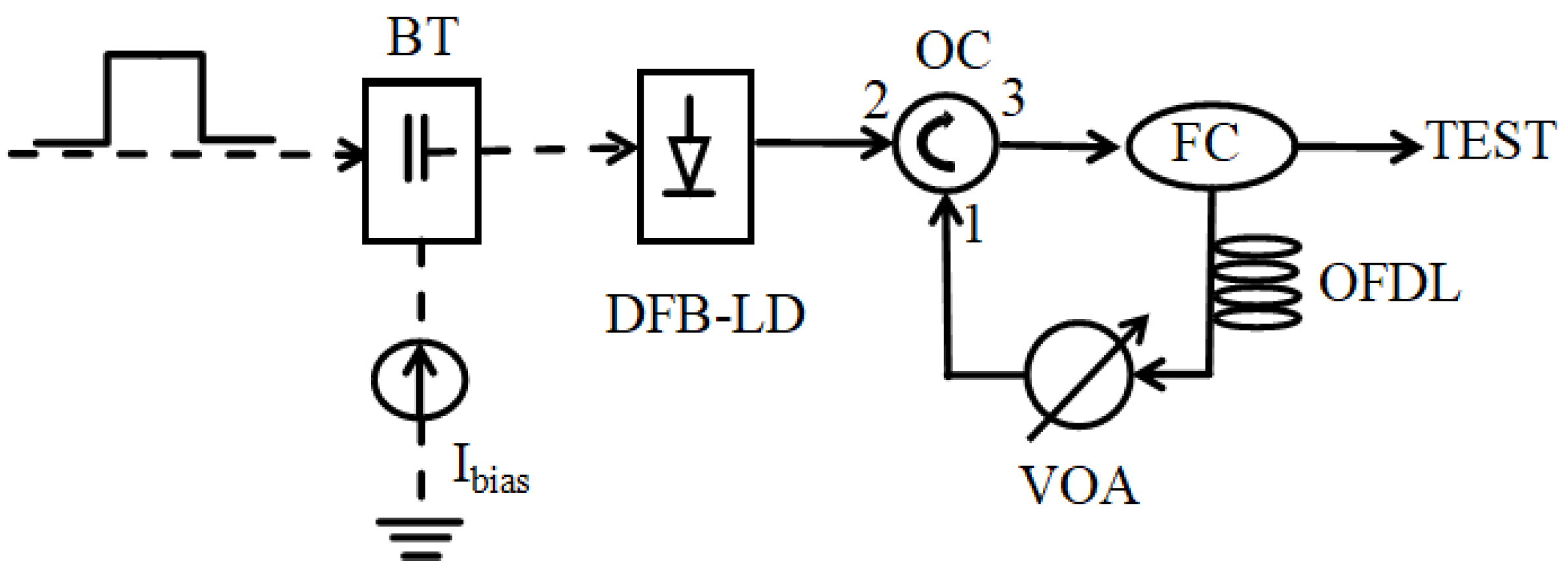
2. Methods and Theory

Figure 1 gives the schematic diagram of the photonic tonic spiking neuron based on a DFB-LD under optical feedback, where the dashed and solid lines represent the electrical and optical paths, respectively. The DFB-LD is driven by a bias current, Ibias, and a rectangular electrical pulse through a Bias Tee. The output of the DFB-LD is directly injected into port 2 of an optical circulator (OC), and the output from port 3 of the OC is divided into two parts by a fiber coupler (FC). One part is used to detect, and the other part is fed back to the DFB-LD after passing through an optical fiber delay line (OFDL), a variable attenuator (VOA), and the OC. The VOA and OFDL are utilized to adjust the feedback strength Kf and feedback delay time τ.
Based on the Lang–Kobayashi model [25], the carrier density N(t) and slowly varying field amplitude E(t) in the DFB-LD under optical feedback can be described as follows:
d E d t = 1 2 1 + i α Γ v g g N 1 τ p E t + K f E ( t τ ) e i ω τ
d N d t = I ( t ) e V a c t R ( N ) v g g ( N ) E ( t ) 2 1 + ϵ E ( t ) 2
where α is the linewidth enhancement factor; Γ is the optical confinement factor; vg is the group velocity; τp is the photon lifetime; ω is the angular oscillation frequency of the laser; I(t) is the time-varying current; e is the electron charge; Vact is the volume of the active region; R(N) is the carrier recombination rate, and ε is the nonlinear gain coefficient. g(N) is the material gain, which is described as
g N = d g d N ( N N t r )
where dg/dN is the differential gain, and Ntr is the transparency carrier density. The carrier recombination rate R(N) is expressed as
R N = A N + B N 2 + C N 3
where A, B, and C are the non-radiative recombination coefficient, spontaneous recombination coefficient, and Auger recombination coefficient, respectively. To mimic the stimulus signal of neurons, a rectangular electrical pulse I(t) is loaded into the laser, which is expressed as
I t = I b i a s + I m     r e c t ( τ r )
where Ibias is the biased current set as the lower current value (Ilo = Ibias); Im is the amplitude of the rectangular pulse rect (τr) of duration τr, and the upper current level is Iup = Ilo + Im = Ibias + Im. Considering that the light beam outputs from the FC, the output power can be expressed as
P t =   η f h ω V a c t 2 π Γ τ p | E ( t ) | 2
where ηf is the product of the differential quantum efficiency and coupling efficiency, and h is Planck’s constant.
Equations (1)–(6) can be numerically solved using the fourth-order Runge–Kutta method. The parameters used in the numerical simulation are listed in Table 1 [26].

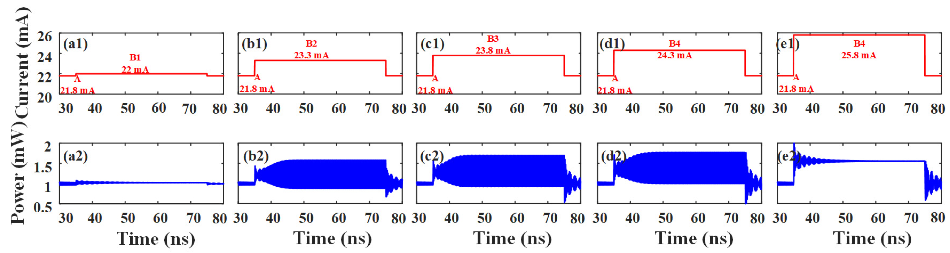
3. Results and Discussion

Firstly, we analyze the nonlinear dynamics of the DFB-LD with optical feedback under different biased currents. Through extracting the extreme values of the output power, the dynamic bifurcations under the delayed-time τ = 1 ns and different feedback strength Kf are shown in Figure 2, where (a–d) are for Kf = 1.45 ns−1, 1.55 ns−1, 1.65 ns−1, and 1.75 ns−1, respectively. From this diagram, it can be seen that the DFB-LD under optical feedback may exhibit different dynamical states, such as a stable state, a period one (P1) state, a multi-periodic state, and a chaotic state. When Ibias is set at a relatively small value, the laser primarily exhibits a multi-periodic state. However, for Ibias with a relatively large value, the laser primarily exhibits a stable state and a P1 state. By adjusting the current, the state switching between the P1 state and the stable state can be realized, which is the basis for the spiking dynamics in photonic neurons [9,14]. Considering that a large Kf is beneficial for enhancing the amplitude envelope and expanding the range of the P1 state, we fix Kf = 1.75 ns−1 in the following discussion unless otherwise specified. Under this case, there are three regions (named I, II, and III, respectively) for which the laser behaves as the P1 state, and the laser exhibits a stable state behavior between two adjacent regions. The laser switches to a stable state from the first P1 state region I at point A, and the stable state lasts until point B1. At points B2–B4, the laser behaves as a P1 state again. At point B5, the laser operates in a stable state. The corresponding currents for such points are given in Figure 2d.
Next, we adopt a rectangular electrical pulse with τr = 40 ns to load into the DFB-LD for generating tonic spiking. Here, the lower current of the pulse Ilo is fixed at 21.8 mA, which is equal to the current for point A, and the upper current of the pulse Iup is set at 22.0 mA, 23.3 mA, 23.8 mA, 24.3 mA, and 25.8 mA corresponding to the current values for points B1–B5, respectively. Figure 3 gives the rectangular electrical pulse signals I(t) (top row) and the corresponding stimulated responses (bottom row). As shown in Figure 3a2, for Iup taken as the current value at point B1, the pulse envelope amplitude gradually decreases over time, and the tonic spiking cannot be generated. For Iup taken as the currents at points B2–B4 (Figure 3b2–d2), the tonic spiking analogous to biological neurons can be observed. However, for Iup taken as the current at point B5 (Figure 3e2), the result is similar to that shown in Figure 3a2. The simulated results demonstrate that for Iup set within region I or region III, the tonic spiking can also be observed. Therefore, in order to generate the tonic spiking analogous to biological neurons, Ilo and Iup are required to make the DFB-LD operate at a stable state and a P1 state, respectively. Notably, the generated tonic spiking possesses a pulse width of sub-nanoseconds, which is faster than the biological neurons with a width of milliseconds.
Then, we discuss the characteristics of the tonic spiking generated under different operation parameters. As mentioned above, under optical feedback with τ = 1 ns, the tonic spiking can be generated for Iup located within regions I, II, or III, and Figure 4a–c shows corresponding results. Here, for each region, three representative results are selected for demonstration. As shown in Figure 4a, for Ilo set at 18.9 mA and three Iup (19.4 mA, 20.0 mA, and 20.9 mA) within region I, the frequencies of the tonic spiking are 3.47 GHz, 3.55 GHz, and 3.65 GHz, respectively. As shown in Figure 4b, for Ilo = 21.8 mA and three Iup (23.3 mA, 23.8 mA, and 24.3 mA) within region II, the frequencies of the tonic spiking are 4.44 GHz, 4.51 GHz, and 4.58 GHz, respectively. As shown in Figure 4c, for Ilo set at 25.4 mA and three Iup (27.4 mA, 28.4 mA, and 28.9 mA) within region III, the frequencies of the tonic spiking are 5.47 GHz, 5.54 GHz, and 5.63 GHz, respectively. As a result, for Iup located at the same P1 region, the tonic spiking generated under larger current values possesses a higher frequency. Due to the discontinuity of P1 regions, the frequency of generated tonic spiking can only be adjusted in discrete segments for given τ = 1 ns. However, through varying the feedback delay time, the frequency of generated tonic spiking can be tuned continuously. Figure 4d gives the frequency of the tonic spiking as a function of Iup under different τ. From this diagram, it can be seen that for a given value of τ, the frequency of the generated tonic spiking exhibits a piecewise–continuous increasing trend with the increase in Iup. For τ taken at different values, the current ranges required to achieve continuous frequency increase in tonic spiking are inconsistent. Therefore, through changing the value of τ from 0.5 ns to 1.2 ns and selecting the matched value within (15.0 mA, 33.0 mA) for Iup, the tonic spiking with the frequency located within (1.12 GHz, 6.30 GHz) can be generated. Under this case, the maximal frequency tuning range of the tonic spiking achieves 5.18 GHz.
Furthermore, the sensitivity of the frequency tunability to the feedback strength Kf and the linewidth enhancement factor α is discussed. Figure 5a gives the frequency tuning range of the tonic spiking varied with ∆Kf, where ∆Kf = (KfKf0)/Kf0, and Kf0 = 1.750 ns−1. From this diagram, it can be seen that for ∆Kf = −10%, the maximal frequency tuning range of the tonic spiking is about 3.5 GHz. For ∆Kf increasing from −8% to 10%, the maximal frequency tuning range shows a stepwise changing trend. For ∆Kf within (−8% −2%), the maximal frequency tuning range remains at around 4.3 GHz. For ∆Kf within (0–10%), the maximum tuning range remains at around 5.18 GHz. Therefore, through setting Kf at the center of such steps, the maximal tuning range of tonic spiking is robust against the deviation of Kf, which ensures the feasibility of this experiment. Figure 5b gives the maximal frequency tuning range of tonic spiking varied with ∆α, where ∆α = (αα0)/α0, and α0 = 3. Similarly, a stepwise changing trend can also be observed in this diagram. As a result, for α taken at certain values, the maximal tuning range of tonic spiking can also be insensitive to the deviation of α.
Finally, a comparison of achieved performances in this work with some key alternative photonic neuron implementations is given in Table 2. Obviously, our scheme not only improves the operational convenience but also expands the tonic spiking frequency tuning range.
Additionally, it should be pointed out that although this work focuses on the numerical simulation based on physical models, artificial intelligence (AI) [27,28] and machine learning (ML) [29] may be other effective techniques for modeling the complex nonlinear dynamics of the DFB-LD under feedback and optimizing the operation parameters.

4. Conclusions

In summary, a scheme for generating the tonic spiking is proposed and numerically demonstrated. For such a scheme, a DFB-LD under optical feedback is utilized as the photonic tonic spiking neuron, which is electrically stimulated by a rectangular electrical pulse with lower current Ilo and upper current Iup. Via the Lang–Kobayashi theoretical model for analyzing the dynamical performances of the DFB-LD under optical feedback, the current regions required for driving the DFB-LD into stable states and period one (P1) states are determined. A rectangular electrical pulse is further introduced as the stimulated signal for generating the tonic spiking. The simulated results demonstrate that Ilo and Iup of the pulse are set to make the DFB-LD operate at a stable state and P1 state, respectively, and the tonic spiking can be successfully generated. For a fixed feedback delay time τ, the frequency of the generated tonic spiking exhibits a piecewise–continuous increasing trend with the increase in Iup. However, through changing the value of τ from 0.5 ns to 1.2 ns and selecting matched Iup within (15.0 mA, 33.0 mA), the tonic spiking with a frequency located within (1.12 GHz, 6.30 GHz) can be generated. It should be pointed out that though the frequency tuning range is obtained under a given feedback strength, it is hoped to be enlarged by adjusting the value of the feedback strength. Therefore, this proposed scheme for generating tonic spiking possesses an application potential in future ultrafast photonic neuro-morphic computing due to its relatively simple structure and ease of control.

Author Contributions

Conceptualization, Z.L. and C.H.; methodology, Z.L., C.H. and Q.W.; validation, Z.L., C.H., Q.W. and P.O.; formal analysis, Z.L.; investigation, Z.L.; resources, Z.W. and G.X.; data curation, Z.L.; writing—original draft preparation, Z.L. and G.X.; writing—review and editing, Z.L. and G.X.; visualization, Z.L.; supervision, Z.W. and G.X.; project administration, Z.W. and G.X.; funding acquisition, Z.W, G.X. and Q.W. All authors have read and agreed to the published version of the manuscript.

Funding

This research was funded by the National Natural Science Foundation of China (62335015, 61875167), the Chongqing Natural Science Foundation (CSTB2022NSCQ-MSX0313), and the Postgraduates’ Research and Innovation Project of Chongqing (CYB23109).

Institutional Review Board Statement

Not applicable.

Informed Consent Statement

Not applicable.

Data Availability Statement

The original contributions presented in this study are included in the article, and further inquiries can be directed to the corresponding author.

Conflicts of Interest

The authors declare no conflicts of interest.

References

  1. Ashtiani, F.; Geers, A.J.; Aflatouni, F. An on-chip photonic deep neural network for image classification. Nature 2022, 606, 501–506. [Google Scholar] [CrossRef] [PubMed]
  2. Shastri, B.J.; Tait, A.N.; Ferreira De Lima, T.; Pernice, W.H.P.; Bhaskaran, H.; Wright, C.D.; Prucnal, P.R. Photonics for artificial intelligence and neuromorphic computing. Nat. Photonics 2021, 15, 102–114. [Google Scholar] [CrossRef]
  3. Wei, C.; Yu, Y.; Wang, Z.; Jiang, L.; Zeng, Z.; Ye, J.; Zou, X.; Pan, W.; Xie, X.; Yan, L. Ultra-wideband waveguide-coupled photodiodes heterogeneously integrated on a thin-film lithium niobate platform. Light Adv. Manuf. 2023, 4, 30. [Google Scholar] [CrossRef]
  4. Brunner, D.; Soriano, M.C.; Mirasso, C.R.; Fischer, I. Parallel photonic information processing at gigabyte per second data rates using transient states. Nat. Commun. 2013, 4, 1364. [Google Scholar] [CrossRef]
  5. Shen, Y.W.; Li, R.Q.; Liu, G.T.; Yu, J.; He, X.; Yi, L.; Wang, C. Deep photonic reservoir computing recurrent network. Optica 2023, 10, 1745–1751. [Google Scholar] [CrossRef]
  6. Robertson, J.; Wade, E.; Kopp, Y.; Bueno, J.; Hurtado, A. Toward neuromorphic photonic networks of ultrafast spiking laser neurons. IEEE J. Sel. Top. Quantum Electron. 2020, 26, 7700715. [Google Scholar] [CrossRef]
  7. Ni, M.; Lin, X.; Tang, X.; Gao, Z.; Xiao, L.; Wang, J.; Ma, F.; Zheng, Q.; Deng, T. Image transmission based on spiking dynamics of electrically controlled VCSEL-SA neuron. Photonics 2021, 8, 238. [Google Scholar] [CrossRef]
  8. Li, Q.; Wang, Z.; Cui, C.; Li, R.; Li, Y.; Liu, B.; Wu, C. Simulating the spiking response of VCSEL-based optical spiking neuron. Opt. Commun. 2018, 407, 327–332. [Google Scholar] [CrossRef]
  9. Lu, Y.; Zhang, W.; Fu, B.; He, Z. Frequency-switched photonic spiking neurons. Opt. Express 2022, 30, 21599–21608. [Google Scholar] [CrossRef]
  10. Temgoua, L.P.G.; Mbe, J.H.T.; Woafo, P. Dynamical behaviors of vertical cavity surface-emitting lasers with an embedded saturable absorber subjected to an on-off keying (OOK) current modulation. Phys. Scr. 2023, 98, 085250. [Google Scholar] [CrossRef]
  11. Hejda, M.; Vaughan, M.; Henning, I.; Al-Seyab, R.; Hurtado, A.; Adams, M. Spiking behaviour in laterally-coupled pairs of VCSELs with applications in neuromorphic photonics. IEEE J. Sel. Top. Quantum Electron. 2023, 29, 1700210. [Google Scholar] [CrossRef]
  12. Xiang, S.Y.; Zhang, Y.H.; Guo, X.X.; Wen, A.J.; Hao, Y. Photonic Generation of Neuron-Like Dynamics Using VCSELs Subject to Double Polarized Optical Injection. J. Light. Technol. 2018, 36, 4227–4234. [Google Scholar] [CrossRef]
  13. Auge, D.; Hille, J.; Mueller, E.; Knoll, A. A survey of encoding techniques for signal processing in spiking neural networks. Neural Process. Lett. 2021, 53, 4693–4710. [Google Scholar] [CrossRef]
  14. Li, J.; Peng, L.; Li, S.S.; Zhang, L.; Ding, X.; Jiang, L.; Zou, X.; Pan, W.; Yan, L. Photonic spiking neuron based on a single VCSEL with optical feedback. Opt. Laser Technol. 2025, 181, 111941. [Google Scholar] [CrossRef]
  15. Xiang, S.Y.; Wen, A.; Pan, W. Emulation of spiking response and spiking frequency property in VCSEL-based photonic neuron. IEEE Photonics J. 2016, 8, 1504109. [Google Scholar] [CrossRef]
  16. Xiang, S.Y.; Shi, Y.; Guo, X.; Zhang, Y.; Wang, H.; Zheng, D.; Song, Z.; Han, Y.; Gao, S.; Zhao, S.; et al. Hardware-algorithm collaborative computing with photonic spiking neuron chip based on an integrated Fabry-Perot laser with a saturable absorber. Optica 2023, 10, 162–171. [Google Scholar] [CrossRef]
  17. Zheng, D.Z.; Xiang, S.Y.; Li, N.Q.; Zhang, Y.H.; Guo, X.X.; Zhu, X.J. The hybrid photonic convolutional neural networks based on SOA and FP-SA. J. Light. Technol. 2024, 42, 8819–8825. [Google Scholar] [CrossRef]
  18. Zhang, Q.; Jiang, N.; Zhang, Y.; Li, A.; Xiong, H.; Hu, G.; Cao, Y.; Qiu, K. On-chip spiking neural networks based on add-drop ring microresonators and electrically reconfigurable phase-change material photonic switches. Photonics Res. 2024, 12, 755–766. [Google Scholar] [CrossRef]
  19. Gouda, M.; Abreu, S.; Bienstman, P. Surrogate gradient learning in spiking networks trained on event-based cytometry dataset. Opt. Express 2024, 32, 16260–16272. [Google Scholar] [CrossRef]
  20. Peng, H.T.; Nahmias, M.A.; de Lima, T.F.; Tait, A.N.; Shastri, B.J. Neuromorphic photonic integrated circuits. IEEE J. Sel. Top. Quantum Electron. 2018, 24, 6101715. [Google Scholar] [CrossRef]
  21. Peng, H.T.; Angelatos, G.; De Lima, T.F.; Nahmias, M.A.; Tait, A.N.; Abbaslou, S.; Shastri, B.J.; Prucnal, P.R. Temporal information processing with an integrated laser neuron. IEEE J. Sel. Top. Quantum Electron. 2020, 26, 5100209. [Google Scholar] [CrossRef]
  22. Xiang, S.Y.; Shi, Y.C.; Zhang, Y.H.; Guo, X.X.; Zheng, L. Photonic integrated neuro-synaptic core for convolutional spiking neural network. Opto-Electron. Adv. 2023, 6, 230140. [Google Scholar] [CrossRef]
  23. Selmi, F.; Braive, R.; Beaudoin, G.; Sagnes, I.; Kuszelewicz, R.; Erneux, T.; Barbay, S. Spike latency and response properties of an excitable micropillar laser. Phys. Rev. E 2016, 94, 042219. [Google Scholar] [CrossRef] [PubMed]
  24. Pammi, V.A.; Alfaro-Bittner, K.; Clerc, M.G.; Barbay, S. Photonic computing with single and coupled spiking micropillar lasers. IEEE J. Sel. Top. Quantum Electron. 2020, 26, 1500307. [Google Scholar] [CrossRef]
  25. Lang, R.; Kobayashi, K. External optical feedback effects on semiconductor injection laser properties. IEEE J. Quantum Electron. 1980, 16, 347–355. [Google Scholar] [CrossRef]
  26. Rosado, A.; Esquivias, I. Complete optical field reconstruction and determination of linewidth enhancement factor in gain-switched semiconductor lasers using the Gerchberg-Saxton algorithm. Opt. Laser Technol. 2025, 181, 111731. [Google Scholar] [CrossRef]
  27. Hamedi, S.; Jahromi, H.D.; Lotfiani, A. Artificial intelligence-aided nanoplasmonic biosensor modeling. Eng. Appl. Artif. Intell. 2023, 118, 105646. [Google Scholar] [CrossRef]
  28. Jahromi, H.D.; Hamedi, S. Artificial intelligence approach for calculating electronic and optical properties of nanocomposites. Mater. Res. Bull. 2021, 141, 111371. [Google Scholar] [CrossRef]
  29. Hamedi, S.; Jahromi, H.D. Performance analysis of all-optical logical gate using artificial neural network. Expert Syst. Appl. 2021, 178, 115029. [Google Scholar] [CrossRef]
Figure 1. Schematic diagram of the photonic tonic spiking neuron based on a DFB-LD under optical feedback. BT: Bias Tee; OC: optical circulator; FC: fiber coupler; VOA: variable attenuator, OFDL: optical fiber delay line. Solid line: optical path; Dashed line: electrical path.
Photonics 12 00510 g001
Figure 2. Output power bifurcation diagrams as a function of Ibias for DFB-LD under optical feedback with τ = 1 ns and Kf = 1.45 ns−1 (a), 1.55 ns−1 (b), 1.65 ns−1 (c), and 1.75 ns−1 (d). In the following discussion, Kf = 1.75 ns−1 is chosen to obtain a relatively large range of P1 states.
Photonics 12 00510 g002
Figure 3. Rectangular electrical pulse signals with τr = 40 ns and different Iup (a1e1) and corresponding stimulated responses of DFB-LD under optical feedback (a2e2).
Photonics 12 00510 g003
Figure 4. Tonic spiking generated under (a) Ilo = 18.9 mA and Iup located within region I, (b) Ilo = 21.8 mA and Iup located within region II, (c) Ilo = 25.4 mA and Iup located within region III, and (d) the frequency of the tonic spiking as a function of Iup under different τs.
Photonics 12 00510 g004
Figure 5. Maximal frequency tuning range of the tonic spiking varied with (a) ∆Kf and (b) ∆α.
Photonics 12 00510 g005
Table 1. Summary of main simulation parameters.
ParametersDescriptionsValuesUnits
ΓOptical confinement factor0.06-
N t r Transparency carrier density 1.3 × 1024m−3
V a c t Volume of active region 1.53 × 10⁻¹⁷m3
ANon-radiative recombination coefficient2.8 × 108s−1
BSpontaneous recombination coefficient1.5 × 10−16m3s−1
CAuger recombination coefficient9.0 × 10−41m6s−1
d g d N Differential gain 4.38 × 10⁻²⁰m2
τ p Photon lifetime 2.17ps
α Linewidth enhancement factor 3-
ϵ Nonlinear gain coefficient 1.97 × 10⁻²³m3
η f Product of the differential quantum efficiency and coupling efficiency 0.17-
Table 2. Summary of related studies in generating tonic spiking.
Refs.YearsPhotonic Spiking NeuronsControl MethodsTuning Ranges (GHz)
[15]2016VCSELspump current and optical injection~4
[12]2018VCSELsoptical injection~1
[22]2023DFB-SAgain current ~2
[14]2025VCSELsoptical feedback~2
This work2025DFB-LDoptical feedback and electrical pulse~5
Disclaimer/Publisher’s Note: The statements, opinions and data contained in all publications are solely those of the individual author(s) and contributor(s) and not of MDPI and/or the editor(s). MDPI and/or the editor(s) disclaim responsibility for any injury to people or property resulting from any ideas, methods, instructions or products referred to in the content.

