Article

Strong Coupling Based on Quasibound States in the Continuum of Nanograting Metasurfaces in Near-Infrared Region

by
Yulun Zhao
1,
Junqiang Li
1,
Yuchang Liu
1,
Yadong Yue
1,
Yongchuan Dang
1,
Yilin Wang
2,
Kun Liang
1,* and
Li Yu
1
1
State Key Laboratory of Information Photonics and Optical Communications, School of Physics, Beijing University of Posts and Telecommunications, Beijing 100876, China
2
College of Mathematics and Physics, Beijing University of Chemical Technology, Beijing 100029, China
*
Author to whom correspondence should be addressed.
Photonics 2025, 12(5), 508; https://doi.org/10.3390/photonics12050508
Submission received: 22 April 2025 / Revised: 12 May 2025 / Accepted: 16 May 2025 / Published: 19 May 2025

Abstract

:
Quasibound states in the continuum (qBICs) have aroused much attention as a feasible stage to investigate optical strong coupling due to their extremely high-quality factors (Q-factors) and extraordinary electromagnetic field enhancement. However, current demonstrations of strong coupling based on qBICs have primarily focused on the visible spectral range, while research in the near-infrared (NIR) regime remains scarce. In this work, we design a nanograting metasurface supporting Friedrich–Wintgen bound states in the continuum (FW BICs). We demonstrate that FW BIC formation stems from destructive interference between Fabry–Pérot cavity modes and metal–dielectric hybrid guided-mode resonances. To investigate the qBIC–exciton coupling system, we simulated the interaction between MoTe2 excitons and nanograting metasurfaces. A Rabi splitting of 55.4 meV was observed, which satisfies the strong coupling criterion. Furthermore, a chiral medium layer is modeled inside the nanograting metasurface by rewriting the weak expression and boundary conditions. A mode splitting of the qBIC–chiral medium system in the circular dichroism (CD) spectrum demonstrates that the chiral response successfully transferred from the chiral medium layer to the exciton–polaritons systems through strong coupling. In comparison to the existing studies, our work demonstrates a significantly larger CD signal under the same Pascal parameters and with a thinner chiral dielectric layer. Our work provides a new ideal platform for investigating the strong coupling based on quasibound states in the continuum, which exhibits promising applications in near-infrared chiral biomedical detection.

1. Introduction

Optical strong coupling refers to a phenomenon that occurs when the energy transfer rate between excitons and photons is much greater than their damping rates, resulting in forming semi-light and semi-matter quasiparticles [1] called exciton–polaritons. Rather than an overlay of eigenstates, two hybrid states are generated, with their energy difference representing the Rabi splitting [2,3]. Exciton–polaritons inherit the characteristics of excitons and photons, which possess fascinating phenomena and applications, for example, Bose–Einstein condensation [4], superfluidity [5], and quantum computation [6]. Lately, transition-metal dichalcogenides (TMDCs) have attracted significant interest in strong coupling investigations because of their stable and strongly bound excitons at room temperature [7,8]. Up to now, TMDCs have been integrated into various qBIC metasurfaces, providing a novel platform for investigating the interaction between low-loss optical modes and excitonic materials [9,10,11].
Recently, bound states in the continuum (BICs) have attracted much attention as a feasible stage to investigate optical strong coupling considering their extremely high-quality factors (Q-factors) and extraordinary enhancement of the electromagnetic field [12,13,14]. BICs are localized and non-radiative states that can coexist with a continuous spectrum of radiating waves [15]. Although the concept of BICs was first introduced by von Neumann and Wigner in quantum mechanics [16], BICs were experimentally verified in many other physics systems, such as electromagnetic fields [17,18,19], acoustic waves [20,21], and water waves [22,23]. Among them, BICs are specifically studied in optical systems, where they are primarily observed in extended structures. Because of the capability to suppress radiation loss, BICs are employed in various applications, such as low-loss fibers [24,25], sensors [26,27], lasers [28,29], and nonlinear optics [30,31,32,33]. Additionally, BICs supported by metasurface structures hold great promise for driving innovations in key nano-optical applications, including the miniaturization of optical devices [34], multifunctional integrated photonics [35], passive radiative cooling [36], and digitally encoded metasurface [37,38]. We can classify BICs into two categories based on their formation mechanisms: symmetry-protected BICs (SP BICs) and Friedrich–Wintgen BICs (FW BICs). The former are positioned at the Γ point in momentum space and governed by the structural symmetry [39,40], while the latter are located at off- Γ points and arise from the destructive interference of multiple radiative channels [41,42]. Quasibound states in the continuum (qBICs), as quasi-modes derived from BICs through breaking structural symmetry or adjusting the incident angle, have attracted widespread attention in the field of optical strong coupling research due to their ability to maintain high-quality factors while exhibiting radiative leakage [33,43].
Chirality, a fundamental geometric property in nature, plays a pivotal role in biopharmaceutical detection. It refers to an object that cannot coincide with its mirror image by simple rotation and translation operations. Two different enantiomers (e.g., D- and L-) exhibit different responses to the left (LCP) and right (RCP) circularly polarized light in intensity, which is known as circular dichroism (CD). Since D- and L- may manifest different pharmacological and toxic properties, the distinguishing detection of enantiomers by nanophotonic devices [44,45] is quite important in medical treatment [46] and food safety [47]. In recent years, studies [48,49,50] have shown that the hybrid quasiparticles produced by the strong coupling between excitons and nano-optics structure will exhibit optical chirality even if only one of the coupled components is chiral, which provides a novel approach for designing of optical chiral devices. However, for chiral strong coupling systems based on molecular chirality, their relatively small CD values limit their applications in chiral biomedicine detection [34,48,51].
In this paper, we design a qBIC nanograting metasurface to achieve strong coupling in near-infrared region. Firstly, we identified the existence of FW BICs in this nanograting metasurface. A vanishing linewidth is observed in the reflectance spectrum, and an infinite Q-factor is obtained at a specific oblique incidence angle, which demonstrates the existence of FW BICs. Furthermore, we explain the formation mechanism of FW BICs in this nanograting metasurface, which arises from the destructive interference between Fabry–Pérot cavity mode and metal–dielectric hybrid guided-mode resonance. Moreover, we observed that both the wavelength and incident angle when FW BICs emerge increase linearly with increasing SiO2 layer thickness. Secondly, the unique anti-crossing behavior with a Rabi splitting of 55.4 meV was observed in the qBIC–MoTe2 exciton system, which indicates the exciton–polaritons are achieved by the interaction between the qBIC mode and MoTe2. In addition, we employed the coupled oscillator model to analyze the coupling behavior by calculating the resonance energy and Hopfield coefficients of each polariton branch. Thirdly, a chiral medium layer was modeled inside the nanograting metasurfaces by rewriting the weak expression and boundary conditions. The chiral exciton–polariton systems were achieved by our designed structure. In comparison with the previous studies, our work demonstrates a significantly larger CD signal under the same Pascal parameters and with a thinner chiral dielectric layer. Our work provides a promising platform for developing optical chiral devices, with potential applications in chiral biomedical detection within the near-infrared region.

2. Results and Discussion

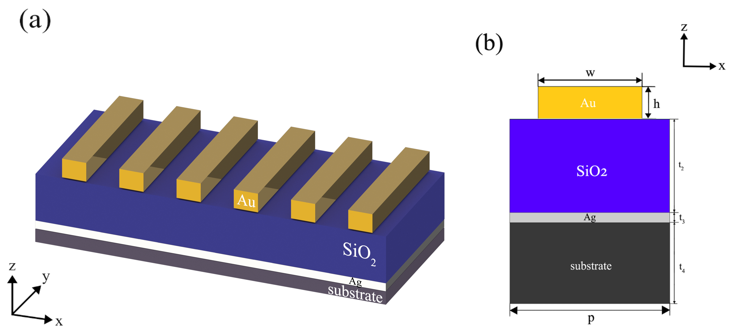
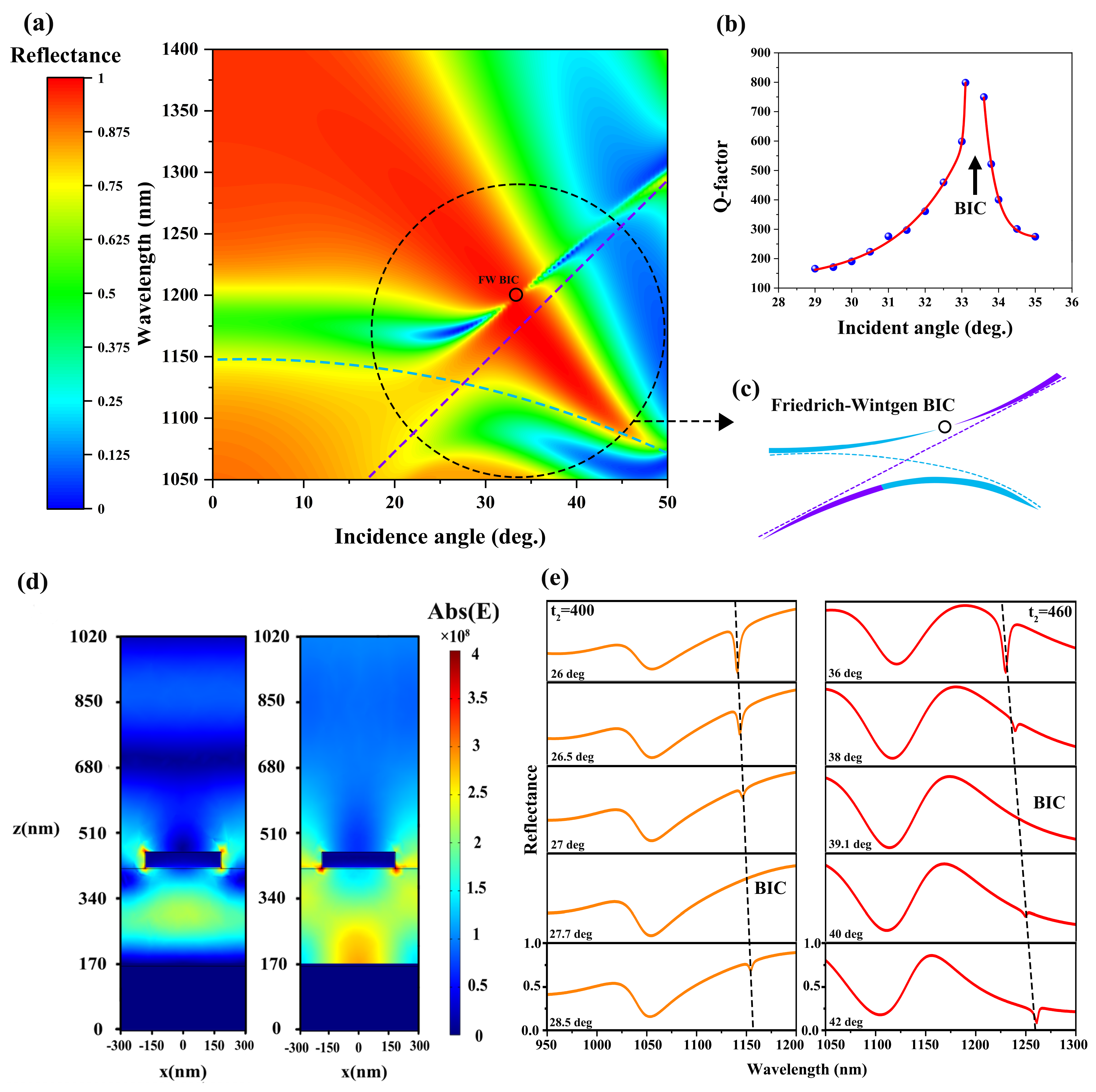
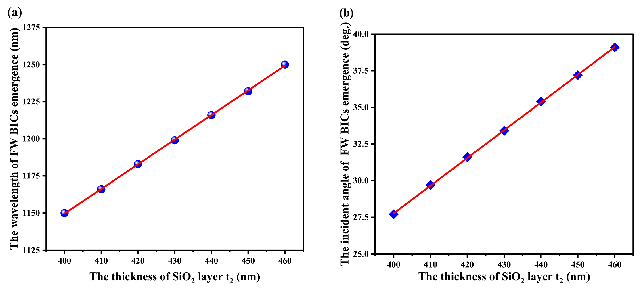
2.1. Friedrich–Wintgen Bound States in the Continuum in Nanograting Metasurfaces

The structure we designed to investigate Friedrich–Wintgen bound states in the continuum (FW BICs) is a nanograting metasurface, which is schematically presented in Figure 1a. For illustration, the structure parameters is shown in Figure 1b as the cross-section picture: grating period p = 600 nm, gold grating line width w = 360 nm, grating thickness h = 70 nm, SiO2 layer thickness t 2 = 430 nm, silver reflector layer thickness t 3 = 290 nm, and substrate thickness t 4 = 570 nm. The SiO2 layer with the refractive index 1.45 is assumed in calculations by finite element method (COMSOL). The permittivities of gold are taken from the Ref. [52].
To identify the existence of the BIC mode in this nanograting metasurface, we calculated the reflectance spectrum of this metal–insulator–metal structure at different incident angles θ when a plane wave with transverse magnetic (TM) polarization strikes, as shown in Figure 2a. Within the black dashed circle marked, it can be observed that when θ increases from 20° to 33.4°, the reflectance dip gradually diminishes, and the spectral linewidth of the resonance mode becomes narrower. Furthermore, we calculated the variation of Q-factor versus different incident angles θ , as shown in Figure 2b. It can be seen that Q-factor approaches infinite at θ = 33.4°, which indicates the formation of a BIC mode. As θ deviates from 33.4°, the Q-factor decreases from infinity to a finite value, revealing the transformation from a BIC to a qBIC.
We classify this BIC as a FW-BIC based on its formation at oblique incidence, rather than symmetry-protected BICs that exclusively emerge at normal incidence (commonly known as the Γ point) [15,42]. The area highlighted by the black dashed circle in Figure 2a is set up to contrast with the sketch of Friedrich–Wintgen BIC band structures, which is drawn in Figure 2c for us to identify this BIC mode. Two dashed lines in Figure 2c, respectively, represent two resonances in their unperturbed states, and two solid bands represent when two resonances pass through one another as a function of a continuous parameter; the coupling between two resonances will result in an anti-crossing of the resonance positions [41]. Meanwhile, the linewidths of two resonances can be altered by the interference between them. When the phase-matching condition is satisfied, a Friedrich–Wintgen BIC, which is circled in Figure 2c, appears at an off- Γ point (or, equivalently, at oblique incidence) due to destructive interference between two resonances [42]. As for the nanograting structure we designed, the blue dashed line and the purple dashed line in Figure 2a, respectively, represent the Fabry–Pérot cavity mode (FP mode) and metal–dielectric hybrid guided-mode resonance when they are unperturbed. To illustrate, the electric field amplitude | E | in x–z plane is simulated for two conditions in Figure 2d: (left) normal incidence ( θ = 0°) with a wavelength of 1175 nm (as the Fabry–Pérot cavity mode) and (right) oblique incidence ( θ = 50°) with 1290 nm (as metal–dielectric hybrid guided-mode resonance).
Furthermore, to investigate how the thickness of SiO2 layer t 2 affects the emergence of FW BICs, t 2 is additionally set as 400 nm and 460 nm, respectively. Figure 2e shows the dynamic process (marked by black dashed line) of FW BICs from emergence to transition into qBICs by changing the incident angles θ under different t 2 . For the situation of t 2 = 400 nm (left picture of Figure 2e), we can observe a clear reflection dip when θ is 26°. The reflection dip gradually disappears as θ increases from 26° to 27.7°, vanishing completely at θ = 27.7° where a FW BIC emerges. As θ increases beyond 27.7°, the reflection dip reappears, signaling the transition from a FW BIC to a qBIC. By comparing the wavelength and the incident angle when FW BICs emerge under different t 2 , as presented in Table 1, it can be observed that both the wavelength and incident angle of the FW BIC emergence increase linearly with increasing t 2 (drawn in Figure 3). These results can be attributed to the increase in SiO2 layer thickness, that is, the Fabry–Pérot cavity thickness increases (the Fabry–Pérot cavity mode arises from optical interference between the Au nanograting and the Ag reflector layer). Consequently, the Fabry–Pérot cavity mode exhibits a redshift in resonance wavelength, corresponding to the blue dashed line move upward in Figure 2a. As a result, the intersection between the blue dashed line (Fabry–Pérot cavity mode) and purple dashed line (metal–dielectric hybrid guided-mode resonance) shifts to the upper left, which manifests in the increasing of the wavelength and incident angle of the FW BIC emergence.

2.2. Near-Infrared Strong Coupling Between qBICs Nanograting Metasurface and MoTe2

Clearly, qBICs exhibit an ultrahigh Q-factor, leading to an extended photon lifetime that is proportional to the value of the Q-factor [53,54]. The prolonged lifetime significantly enhances the probability of realizing strong light–matter interaction [55,56]. Therefore, we opt to utilize a qBIC nanograting metasurface to interact with excitonic materials for achieving near-infrared strong coupling, as illustrated in Figure 4a.
MoTe2, as a transition-metal dichalcogenide, exhibits an exciton resonance in the near-infrared (NIR) range, making it suitable for achieving NIR strong light–matter interaction. The dielectric response of MoTe2 under artificial-permittivity approximation is well captured by the Lorentz model [55]: ε ( ω ) = ε 0 + f 0 ω 0 2 ω 0 2 ω 2 i Γ 0 ω , where ε 0 = 2.25 is the background permittivity, f 0 = 1 is the oscillator strength, and ω is the resonant energy of the incident light. ω 0 = 1.06 eV and Γ 0 = 2 γ 0 = 79 meV are the resonance energy and damping rate of MoTe2, respectively. The transmission spectrum of MoTe2 is shown in Figure 4b, with an exciton resonance at 1170 nm. The spectral overlap between MoTe2 excitons and qBIC modes in the nanograting metasurface, along with matched damping rates, enables the realization of strong coupling in NIR region. We simulated the interaction between the MoTe2 excitons and qBIC nanograting metasurface as functions of the grating period when the incident angle θ was 26°, as shown in Figure 4c (the ratio between the width of the gold grating line and the grating period remains unchanged, namely, w p is a constant). A unique anti-crossing behavior can be observed in reflectance spectrum, and the Rabi splitting is about Ω = 55.4 meV at zero detuning (when p = 588.4 nm), which satisfies the strong coupling criterion: Ω > Γ 0 + Γ q B I C 2 ( Γ q B I C = 17.9 meV is the damping rate of qBIC mode when θ = 26°) suggested the qBIC–MoTe2 hybrid system had attained the strong coupling regime. Additionally, we employed coupled-oscillator model to calculate their interaction [2] as
ω q B I C i Γ q B I C 2 g g ω 0 i Γ 0 2 c a 1 a 2 = ω a 1 a 2
where ω q B I C is the resonant energy of qBIC mode; g represents the coupling strength; a 1 and a 2 are the Hopfield coefficients (satisfying | a 1 | 2 + | a 2 | 2 = 1 ). | a 1 | 2 and | a 2 | 2 represent the fraction of qBIC mode and MoTe2 in hybrids states, respectively. Two black dashed lines in Figure 4c represent the qBIC mode resonance energy (slope one) and MoTe2 exciton resonance energy (horizontal one), respectively. By solving Equation (1), we obtain the resonance energy of the upper polariton branch (UPB) and lower polariton branch (LPB): ω ± = ω B I C + ω 0 2 i Γ B I C + Γ 0 4 ± g 2 + ( ω B I C ω 0 2 i Γ B I C Γ 0 4 ) 2 , corresponding to the purple solid line and the red solid line in Figure 4c, respectively. To investigate the effect of MoTe2 thickness t 1 on the coupling systems, t 1 is set as 9 nm, 10 nm, 13 nm, and 15 nm. As t 1 increases from 9 nm to 15 nm, the number of excitons participating in the coupling rises, resulting in a more pronounced splitting pattern and an increase in the Rabi splitting value from 35.8 meV to 85.9 meV (Figure 4d). Moreover, according to Equation (1), the Hopfield coefficients are calculated (Figure 4e,f) for t 1 = 11 nm, representing the fractions of MoTe2 excitons and qBIC modes in the upper and lower polariton branches as functions of grating period p.

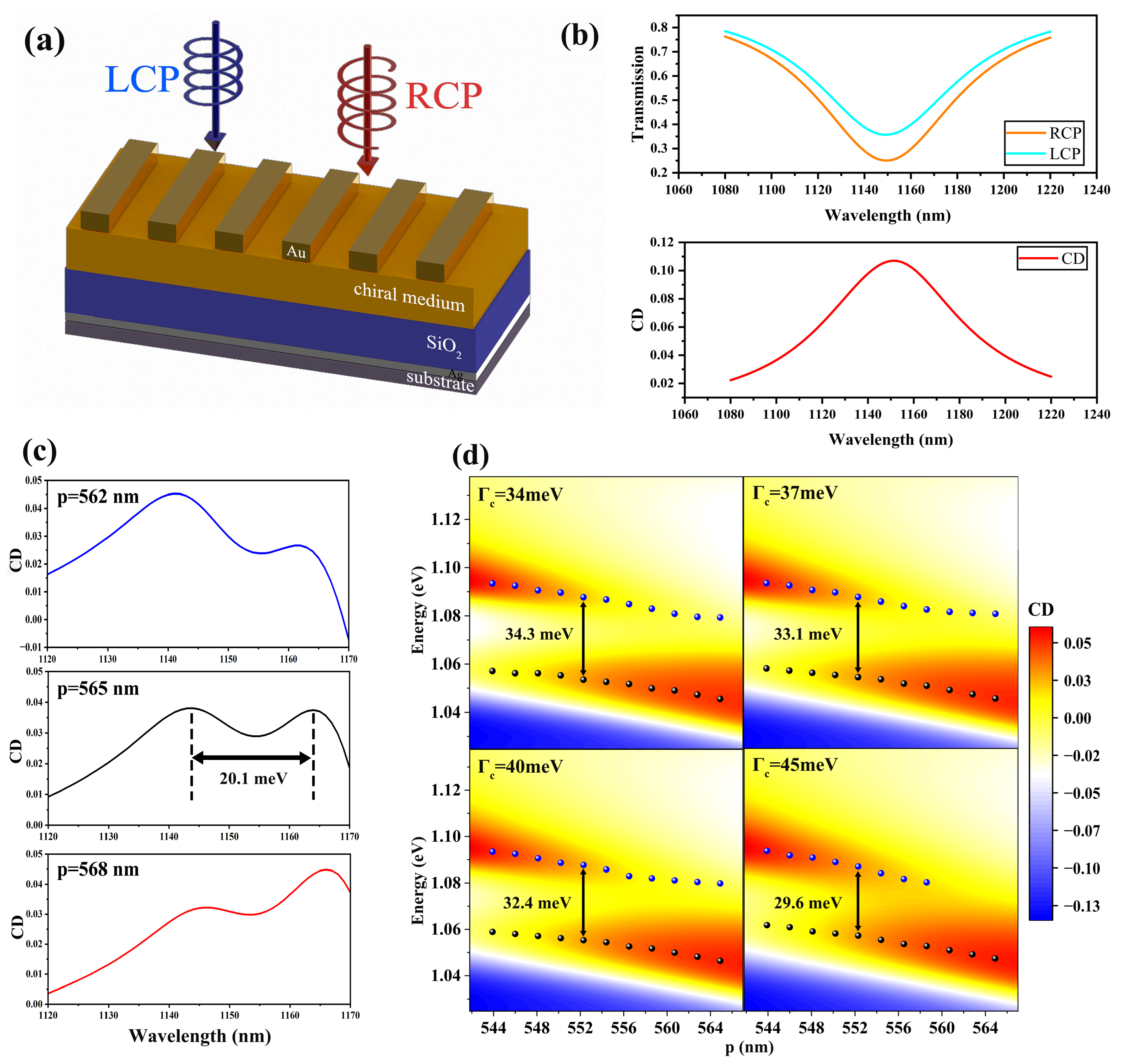
2.3. Near-Infrared Chiral Strong Coupling Between qBIC and Chiral Medium

Chiral strong coupling has remained a pivotal research focus in optics due to its extensive applications. For the chiral biological detection, molecular-originated chiral coupling systems outperform structural-originated ones as they directly mirror the biological detection scenarios where solution chirality stems from dissolved chiral molecules rather than artificial chiral nanostructures. In finite element simulations, the implementation of chiral molecular effects is typically achieved through the incorporation of a chiral medium layer as an equivalent modeling approach [48,51].
In this study, we model the chiral medium by deriving the chiral wave equation through combining Maxwell’s equations and the constitutive relations of chiral medium. The non-magnetic bi-isotropic constitutive relations of the chiral medium are as follows [48]: D B = ε ε 0 i κ / c i κ / c μ 0   E H , where c is the speed of light, ε0 and ε are the vacuum permittivity and relative permittivity, μ0 is vacuum permeability, and κ denotes the Pasteur parameter, which quantifies the chirality of a medium. Combining Maxwell’s equations with the constitutive relations and considering the electric field E has the form of E(r, t) = E ( r ) · e i ω t in COMSOL, we derive the wave equation for the chiral medium.
× × E 2 ω κ c × E ω 2 c 2 ( ε κ 2 ) · E = 0
In particular, when κ = 0, Equation (2) turns into the non-chiral wave equation. Based on the derived chiral wave equation, we reformulate the weak form expression and corresponding boundary conditions in COMSOL 6.1 [57]. By multiplying the test function V on both sides of Equation (2) and integrating [58], we obtain the weak form.
0 = Ω [ ( × E ) · ( × V ) + 2 ω κ c V · × E + ω 2 c 2 ( ε κ 2 ) V · E ] d v Ω e n · ( × E ) × V d s
where e n is the normal unit vector of the integral interface. The weak form in Equation (3) consists of two terms: a volume integral and a surface integral. Since the surface integral term is constrained by boundary conditions, the implementation of Equation (3) in COMSOL is written as follows:
( × E ) · ( × V ) + 2 ω κ c V · × E + ω 2 c 2 ( ε κ 2 ) V · E
Both the surface integral in Equation (3) and the continuity condition of electromagnetic fields are incorporated into the boundary conditions for Equation (4). Therefore, an additional boundary condition specifying the surface current density must be imposed at the chiral medium interface.
J s = i c μ 0 ( κ 1 κ 2 ) ( n 1 , 2 × E )
where n 1 , 2 is the unit normal vector of the interface. κ 1 and κ 2 are the Pasteur parameters of each material on both sides of an interface. The schematic of our designed model is shown in Figure 5a, where the thickness of chiral medium layer is t c . For the lower interface of the chiral medium layer, the materials on each side are the chiral medium and SiO2, respectively. So the Pasteur parameters should be set as κ 1 = κ and κ 2 = κ S i O 2 , where the Pasteur parameters κ of chiral medium is described by Lorentz model: κ ( ω ) = κ 0 ω c 2 ω c 2 ω 2 i Γ c ω . We set the Pasteur parameter amplitude κ 0 as 0.03, with a damping rate Γ c = 34 meV and a resonant energy ω c = 1.078 eV. Since the SiO2 layer is achiral, we set κ 2 = κ S i O 2 = 0. For the upper interface of the chiral medium layer, the adjacent materials are the gold–air alternating layers and the chiral medium. Consequently, we set the Pasteur parameters as κ 1 = κ g o l d a i r = 0 and κ 2 = κ . Based on the preceding analysis, the additional boundary condition (Equation (5)) at the lower interface simplifies to J s l o w e r = i c μ 0 κ ( n 1 , 2 × E ) , while for the upper interface, the corresponding condition is J s u p p e r = i c μ 0 κ ( n 1 , 2 × E ) .
The permittivity of the chiral medium layer is described by the Lorentz model: ε c ( ω ) = ε 0 + f 0 ω c 2 ω c 2 ω 2 i Γ c ω , where the background permittivity is ε 0 = 2.25, and the ocillator strength is f 0 = 1. Modeling the chiral medium layer by the method described above, we observe a distinct optical response for LCP and RCP. Figure 5b shows (top) the transmission spectra of the bare chiral medium layer under LCP and RCP illumination and (bottom) the corresponding circular dichroism spectrum CD = T L C P T R C P .
Furthermore, we employed the finite element method (FEM) to simulate the interaction between quasi BIC modes and chiral medium under θ = 30°, t c = 10 nm. When the nanograting period p is set to 562 nm, 565 nm, and 568 nm, the CD spectra (Figure 5c) exhibit significant mode splitting under blue-detuned (p = 562 nm), zero-detuned (p = 565 nm), and red-detuned (p = 568 nm) conditions. A Rabi splitting Ω c = 20.1 meV was observed at zero-detuning, satisfying the strong coupling criterion: Ω c > Γ c + Γ q B I C 2 ( Γ q B I C is 5.2 meV in the situation of θ = 30°). This confirms the realization of chiral exciton–polaritons in our designed structure, demonstrating the successful transfer of optical chirality from the chiral medium layer to the exciton–polariton system through strong coupling.
Notably, we categorize chiral strong coupling systems into two types based on the sources of chirality: structural chirality systems (as exemplified by the first two rows in Table 2, introducing structural symmetry-breaking into metasurface) and molecular chirality systems (in finite element simulations, chiral medium layers are typically employed to emulate molecular chirality). The CD signals from strong structural chirality coupling systems are usually stronger than those from molecular ones. Particularly, in BIC-supporting structures, the breaking of both in-plane and out-of-plane symmetries enables intrinsic chiral BICs to reach a CD value of 1 [59], consequently boosting the CD response in the coupled system. However, compared to structurally chiral systems, molecular chiral systems are more closely aligned with the practical needs of chiral biomedical detection and identification as the chirality in biomedical sample solutions arises from dissolved molecules rather than engineered nanostructures. In comparison with the previous works that also utilize chiral medium layers to achieve chiral strong coupling, our work demonstrates a significantly larger CD signal under the same Pasteur parameter amplitude κ 0 and with a thinner chiral medium layer (Rows 3–5 in Table 2).
Moreover, we investigated the effect of the chiral medium damping rate ( Γ c ) on the coupled system. When Γ c is set to 34 meV, 37 meV, 40 meV, and 45 meV, the CD spectra of the chiral coupled system are shown as a function of nanograting period p under θ = 26° and t c = 20 nm (Figure 5d). It can be observed that mode splitting amplitudes decrease with increasing Γ c . Especially at Γ c = 45 meV, the CD peak becomes single and the anti-crossing behavior disappears. The splitting energy Ω c = 29.6 meV < Γ c + Γ q B I C 2 , violating the strong coupling criterion, which means the interaction between qBICs and the chiral medium is at the weak coupling region.

3. Conclusions

In summary, we designed a qBIC-supporting nanograting metasurface to realize near-infrared strong coupling with MoTe2 excitons and chiral medium, respectively. Firstly, we identified the existence of FW BICs in the reflection spectrum of the nanograting metasurfaces and analyzed the underlying mechanism for FW BIC emergence. Secondly, an obvious mode splitting was observed in the reflection spectrum of qBIC–MoTe2 exciton systems, which satisfied the strong coupling criterion. Additionally, we used the coupled-oscillator model to analyze the coupling behavior by calculating the energy and Hopfield coefficients of each polariton branch. Moreover, the chiral medium layer is successfully modeled by rewriting the weak expression and boundary conditions in COMSOL; then, the chiral exciton–polariton systems were achieved by our designed structure. In comparison with the existing studies, our work demonstrates a significantly larger CD signal under the same Pascal parameters and with a thinner chiral dielectric layer. Our work provides a promising strategy for optical chiral devices, which exhibits potential applications in chiral biomedical detection in near-infrared regions.

Author Contributions

Y.Z.: conceptualization, methodology, validation, investigation, and writing—review and editing. J.L.: software, formal analysis, resources, and data curation. Y.L.: writing—review and editing. Y.Y. and Y.D.: supervision. K.L. and Y.W.: project administration. L.Y.: funding acquisition. All authors have read and agreed to the published version of the manuscript.

Funding

This study was supported by National Natural Science Foundation of China (12204061 and 12174037); State Key Laboratory of Information Photonics and Optical Communications (No. IPOC2024ZT02).

Institutional Review Board Statement

Not applicable.

Informed Consent Statement

Not applicable.

Data Availability Statement

All data are available from the authors upon reasonable request.

Conflicts of Interest

The authors declare no conflicts of interest.

References

  1. Santhosh, K.; Bitton, O.; Chuntonov, L.; Haran, G. Vacuum Rabi splitting in a plasmonic cavity at the single quantum emitter limit. Nat. Commun. 2016, 7, ncomms11823. [Google Scholar] [CrossRef] [PubMed]
  2. Törmä, P.; Barnes, W.L. Strong coupling between surface plasmon polaritons and emitters: A review. Rep. Prog. Phys. 2014, 78, 013901. [Google Scholar] [CrossRef]
  3. Li, S.; Fang, Y.; Wang, J. Control of light–matter interactions in two-dimensional materials with nanoparticle-on-mirror structures. Opto-Electron. Sci. 2024, 3, 240011. [Google Scholar] [CrossRef]
  4. Kasprzak, J.; Richard, M.; Kundermann, S.; Baas, A.; Jeambrun, P.; Keeling, J.M.J.; Marchetti, F.; Szymańska, M.; André, R.; Staehli, J.; et al. Bose–Einstein condensation of exciton polaritons. Nature 2006, 443, 409–414. [Google Scholar] [CrossRef] [PubMed]
  5. Lerario, G.; Fieramosca, A.; Barachati, F.; Ballarini, D.; Daskalakis, K.S.; Dominici, L.; De Giorgi, M.; Maier, S.A.; Gigli, G.; Kéna-Cohen, S.; et al. Room-temperature superfluidity in a polariton condensate. Nat. Phys. 2017, 13, 837–841. [Google Scholar] [CrossRef]
  6. Ghosh, S.; Liew, T.C. Quantum computing with exciton-polariton condensates. Npj Quantum Inf. 2020, 6, 16–21. [Google Scholar] [CrossRef]
  7. Kleemann, M.E.; Chikkaraddy, R.; Alexeev, E.M.; Kos, D.; Carnegie, C.; Deacon, W.; de Pury, A.C.; Große, C.; de Nijs, B.; Mertens, J.; et al. Strong-coupling of WSe2 in ultra-compact plasmonic nanocavities at room temperature. Nat. Commun. 2017, 8, 1296–1302. [Google Scholar] [CrossRef]
  8. Ramasubramaniam, A. Large excitonic effects in monolayers of molybdenum and tungsten dichalcogenides. Phys. Rev. B Condens. Matter Mater. Phys. 2012, 86, 115409. [Google Scholar] [CrossRef]
  9. Qin, M.; Duan, J.; Xiao, S.; Liu, W.; Yu, T.; Wang, T.; Liao, Q. Strong coupling between excitons and quasibound states in the continuum in bulk transition metal dichalcogenides. Phys. Rev. B 2023, 107, 045417. [Google Scholar] [CrossRef]
  10. Zhou, H.; Qin, M.; Xu, H.; Wei, G.; Li, H.; Gao, W.; Liu, J.; Wu, F. Photonic spin-controlled self-hybridized exciton-polaritons in WS 2 metasurfaces driven by chiral quasibound states in the continuum. Phys. Rev. B 2024, 109, 125201. [Google Scholar] [CrossRef]
  11. Xie, P.; Ding, Q.; Liang, Z.; Shen, S.; Yue, L.; Zhang, H.; Wang, W. Cavity-assisted boosting of self-hybridization between excitons and photonic bound states in the continuum in multilayers of transition metal dichalcogenides. Phys. Rev. B 2023, 107, 075415. [Google Scholar] [CrossRef]
  12. Al-Ani, I.A.; As’ Ham, K.; Huang, L.; Miroshnichenko, A.E.; Hattori, H.T. Enhanced strong coupling of TMDC monolayers by bound state in the continuum. Laser Photonics Rev. 2021, 15, 2100240. [Google Scholar] [CrossRef]
  13. Bogdanov, A.A.; Koshelev, K.L.; Kapitanova, P.V.; Rybin, M.V.; Gladyshev, S.A.; Sadrieva, Z.F.; Samusev, K.B.; Kivshar, Y.S.; Limonov, M.F. Bound states in the continuum and Fano resonances in the strong mode coupling regime. Adv. Photonics 2019, 1, 016001. [Google Scholar] [CrossRef]
  14. Huang, L.; Xu, L.; Rahmani, M.; Neshev, D.; Miroshnichenko, A.E. Pushing the limit of high-Q mode of a single dielectric nanocavity. Adv. Photonics 2021, 3, 016004. [Google Scholar] [CrossRef]
  15. Hsu, C.W.; Zhen, B.; Stone, A.D.; Joannopoulos, J.D.; Soljačić, M. Bound states in the continuum. Nat. Rev. Mater. 2016, 1, 1–13. [Google Scholar] [CrossRef]
  16. von Neumann, J.; Wigner, E.P. Über merkwürdige diskrete Eigenwerte. In The Collected Works of Eugene Paul Wigner: Part A: The Scientific Papers; Springer: Berlin/Heidelberg, Germany, 1993; pp. 291–293. [Google Scholar]
  17. Longhi, S. Bound states in the continuum in a single-level Fano-Anderson model. Eur. Phys. J. B 2007, 57, 45–51. [Google Scholar] [CrossRef]
  18. Marinica, D.; Borisov, A.; Shabanov, S. Bound states in the continuum in photonics. Phys. Rev. Lett. 2008, 100, 183902. [Google Scholar] [CrossRef]
  19. Bulgakov, E.N.; Sadreev, A.F. Bound states in the continuum in photonic waveguides inspired by defects. Phys. Rev. B Condens. Matter Mater. Phys. 2008, 78, 075105. [Google Scholar] [CrossRef]
  20. Yamanouchi, K.; Shibayama, K. Propagation and amplification of Rayleigh waves and piezoelectric leaky surface waves in LiNbO3. J. Appl. Phys. 1972, 43, 856–862. [Google Scholar] [CrossRef]
  21. Lyapina, A.; Maksimov, D.; Pilipchuk, A.; Sadreev, A. Bound states in the continuum in open acoustic resonators. J. Fluid Mech. 2015, 780, 370–387. [Google Scholar] [CrossRef]
  22. McIver, M. An example of non-uniqueness in the two-dimensional linear water wave problem. J. Fluid Mech. 1996, 315, 257–266. [Google Scholar] [CrossRef]
  23. McIver, M. Trapped modes supported by submerged obstacles. Proc. R. Soc. Lond. Ser. A Math. Phys. Eng. Sci. 2000, 456, 1851–1860. [Google Scholar] [CrossRef]
  24. Benabid, F.; Knight, J.C.; Antonopoulos, G.; Russell, P.S.J. Stimulated Raman scattering in hydrogen-filled hollow-core photonic crystal fiber. Science 2002, 298, 399–402. [Google Scholar] [CrossRef]
  25. Couny, F.; Benabid, F.; Roberts, P.; Light, P.; Raymer, M. Generation and photonic guidance of multi-octave optical-frequency combs. Science 2007, 318, 1118–1121. [Google Scholar] [CrossRef]
  26. Jahani, Y.; Arvelo, E.R.; Yesilkoy, F.; Koshelev, K.; Cianciaruso, C.; De Palma, M.; Kivshar, Y.; Altug, H. Imaging-based spectrometer-less optofluidic biosensors based on dielectric metasurfaces for detecting extracellular vesicles. Nat. Commun. 2021, 12, 3246–3255. [Google Scholar] [CrossRef] [PubMed]
  27. Yesilkoy, F.; Arvelo, E.R.; Jahani, Y.; Liu, M.; Tittl, A.; Cevher, V.; Kivshar, Y.; Altug, H. Ultrasensitive hyperspectral imaging and biodetection enabled by dielectric metasurfaces. Nat. Photonics 2019, 13, 390–396. [Google Scholar] [CrossRef]
  28. Kodigala, A.; Lepetit, T.; Gu, Q.; Bahari, B.; Fainman, Y.; Kanté, B. Lasing action from photonic bound states in continuum. Nature 2017, 541, 196–199. [Google Scholar] [CrossRef]
  29. Hwang, M.S.; Lee, H.C.; Kim, K.H.; Jeong, K.Y.; Kwon, S.H.; Koshelev, K.; Kivshar, Y.; Park, H.G. Ultralow-threshold laser using super-bound states in the continuum. Nat. Commun. 2021, 12, 4135–4143. [Google Scholar] [CrossRef]
  30. Vabishchevich, P.; Kivshar, Y. Nonlinear photonics with metasurfaces. Photonics Res. 2023, 11, B50–B64. [Google Scholar] [CrossRef]
  31. Abujetas, D.R.; Barreda, Á.; Moreno, F.; Litman, A.; Geffrin, J.M.; Sánchez-Gil, J.A. High-Q transparency band in all-dielectric metasurfaces induced by a quasi bound state in the continuum. Laser Photonics Rev. 2021, 15, 2000263. [Google Scholar] [CrossRef]
  32. Koshelev, K.; Kruk, S.; Melik-Gaykazyan, E.; Choi, J.H.; Bogdanov, A.; Park, H.G.; Kivshar, Y. Subwavelength dielectric resonators for nonlinear nanophotonics. Science 2020, 367, 288–292. [Google Scholar] [CrossRef] [PubMed]
  33. Li, J.; Deng, X.; Liang, X.; He, C.; Zhou, P.; Wang, T.; Liang, K.; Yu, L. Second Harmonic Generation from exciton-polaritons: Strong coupling between monolayer WS2 and multilayer WSe2 metasurfaces Quasibound states in the continuum. Opt. Commun. 2024, 570, 130935. [Google Scholar] [CrossRef]
  34. Luo, Z.; Ding, Y.; Peng, F.; Wei, G.; Wang, Y.; Wu, S.T. Ultracompact and high-efficiency liquid-crystal-on-silicon light engines for augmented reality glasses. Opto-Electron. Adv. 2024, 7, 240039. [Google Scholar] [CrossRef]
  35. Wu, Y.; Yang, Q.; Shen, B.; Tao, Y.; Zhang, X.; Tao, Z.; Xing, L.; Ge, Z.; Li, T.; Bai, B.; et al. Multifunctional mixed analog/digital signal processor based on integrated photonics. Opto-Electron. Sci. 2024, 3, 240012. [Google Scholar] [CrossRef]
  36. Zhang, Y.; Chen, Y.; Wang, T.; Zhu, Q.; Gu, M. Ultrahigh performance passive radiative cooling by hybrid polar dielectric metasurface thermal emitters. Opto-Electron. Adv. 2024, 7, 230194. [Google Scholar] [CrossRef]
  37. Jing, X.; Tang, X.; Tian, Y.; Kong, Z.; Li, C.; Shen, C.; Hong, Z. Enhancement of diffraction efficiency based on the addition principle of coded digital gratings. J. Light. Technol. 2022, 40, 136–142. [Google Scholar] [CrossRef]
  38. Chen, Y.; Zhang, S.; Tian, Y.; Li, C.; Huang, W.; Liu, Y.; Jin, Y.; Fang, B.; Hong, Z.; Jing, X. Focus control of wide-angle metalens based on digitally encoded metasurface. Opto-Electron. Adv. 2024, 7, 240095. [Google Scholar] [CrossRef]
  39. Koshelev, K.; Lepeshov, S.; Liu, M.; Bogdanov, A.; Kivshar, Y. Asymmetric metasurfaces with high-Q resonances governed by bound states in the continuum. Phys. Rev. Lett. 2018, 121, 193903. [Google Scholar] [CrossRef]
  40. Fan, K.; Shadrivov, I.V.; Padilla, W.J. Dynamic bound states in the continuum. Optica 2019, 6, 169–173. [Google Scholar] [CrossRef]
  41. Chern, R.L.; Yang, H.C.; Chang, J.C. Bound states in the continuum in asymmetric dual-patch metasurfaces. Opt. Express 2023, 31, 16570–16581. [Google Scholar] [CrossRef]
  42. Azzam, S.I.; Shalaev, V.M.; Boltasseva, A.; Kildishev, A.V. Formation of bound states in the continuum in hybrid plasmonic-photonic systems. Phys. Rev. Lett. 2018, 121, 253901. [Google Scholar] [CrossRef]
  43. Deng, X.; Liang, X.; He, C.; Li, J.; Zhou, P.; Liang, K.; Yu, L. Realization of exciton-polariton optical chirality based on strong coupling between intrinsic chiral quasibound states in the continuum and monolayer WS2. Opt. Express 2024, 32, 11522–11533. [Google Scholar] [CrossRef] [PubMed]
  44. Sapunova, A.A.; Yandybaeva, Y.I.; Zakoldaev, R.A.; Afanasjeva, A.V.; Andreeva, O.V.; Gladskikh, I.A.; Vartanyan, T.A.; Dadadzhanov, D.R. Laser-induced chirality of plasmonic nanoparticles embedded in porous matrix. Nanomaterials 2023, 13, 1634. [Google Scholar] [CrossRef]
  45. Gladskikh, I.A.; Toropov, N.A.; Dadadzhanov, D.R.; Baranov, M.A.; Gladskikh, A.A.; Mirzoyan, G.; Markovich, G.; Vartanyan, T.A. Laser-Based Reshaping of Self-Organized Metasurfaces of Supported Ag Nanoparticles for Encoding Tunable Linear Dichroism Patterns. ACS Appl. Nano Mater. 2024, 7, 11342–11349. [Google Scholar] [CrossRef]
  46. Abdel-Megied, A.M.; Hanafi, R.S.; Aboul-Enein, H.Y. A chiral enantioseparation generic strategy for anti-Alzheimer and antifungal drugs by short end injection capillary electrophoresis using an experimental design approach. Chirality 2018, 30, 165–176. [Google Scholar] [CrossRef]
  47. Brenna, E.; Fuganti, C.; Serra, S. Enantioselective perception of chiral odorants. Tetrahedron Asymmetry 2003, 14, 1–42. [Google Scholar] [CrossRef]
  48. Baranov, D.G.; Munkhbat, B.; Länk, N.O.; Verre, R.; Käll, M.; Shegai, T. Circular dichroism mode splitting and bounds to its enhancement with cavity-plasmon-polaritons. Nanophotonics 2020, 9, 283–293. [Google Scholar] [CrossRef]
  49. Wu, F.; Guo, J.; Huang, Y.; Liang, K.; Jin, L.; Li, J.; Deng, X.; Jiao, R.; Liu, Y.; Zhang, J.; et al. Plexcitonic optical chirality: Strong exciton–plasmon coupling in chiral j-aggregate-metal nanoparticle complexes. ACS Nano 2020, 15, 2292–2300. [Google Scholar] [CrossRef]
  50. Wu, F.; Li, N.; Ding, B.; Zhang, W. Plasmon–exciton strong coupling effects of the chiral hybrid nanostructures based on the plexcitonic born–kuhn model. ACS Photonics 2023, 10, 1356–1366. [Google Scholar] [CrossRef]
  51. Deng, X.; Li, J.; Jin, L.; Wang, Y.; Liang, K.; Yu, L. Plexcitonic optical chirality in the chiral plasmonic structure-microcavity-exciton strong coupling system. Opt. Express 2023, 31, 32082–32092. [Google Scholar] [CrossRef] [PubMed]
  52. Johnson, P.B.; Christy, R.W. Optical constants of the noble metals. Phys. Rev. B 1972, 6, 4370–4379. [Google Scholar] [CrossRef]
  53. Novotny, L.; Hecht, B. Principles of Nano-Optics; Cambridge University Press: Cambridge, UK, 2012. [Google Scholar]
  54. Vahala, K.J. Optical microcavities. Nature 2003, 424, 839–846. [Google Scholar] [CrossRef]
  55. Gao, C.; You, S.; Zhang, Y.; Wang, L.; Duan, H.; He, H.; Xie, Q.; Zhou, C. Strong coupling between excitons and quasi-bound states in the continuum mode with stable resonance wavelength in the near-infrared region. Appl. Phys. Lett. 2024, 124, 051701. [Google Scholar] [CrossRef]
  56. Li, H.; Qin, M.; Ren, Y.; Hu, J. Angle-independent strong coupling between plasmonic magnetic resonances and excitons in monolayer WS2. Opt. Express 2019, 27, 22951–22959. [Google Scholar] [CrossRef] [PubMed]
  57. Klimov, V.; Zabkov, I.; Pavlov, A.; Guzatov, D. Eigen oscillations of a chiral sphere and their influence on radiation of chiral molecules. Opt. Express 2014, 22, 18564–18578. [Google Scholar] [CrossRef]
  58. Zhang, Y.; Birgisson, B.; Lytton, R.L. Weak form equation–based finite-element modeling of viscoelastic asphalt mixtures. J. Mater. Civ. Eng. 2016, 28, 04015115. [Google Scholar] [CrossRef]
  59. Lv, S.; Hu, F.; Luo, W.; Xu, H.; An, L. Design of tunable selective light-absorbing metasurfaces driven by intrinsically chiral quasi-bound states in the continuum. Opt. Express 2024, 32, 30053–30064. [Google Scholar] [CrossRef]
  60. Xie, S.; Chen, J.; Sun, M.; Sun, S.; Zeng, Z.; Guan, X.; Yang, S. Strong coupling between excitons and chiral quasibound states in the continuum of the bulk WS2 metasurface. Opt. Express 2024, 32, 32523–32537. [Google Scholar] [CrossRef]
Figure 1. The nanograting metasurface we designed to investigate Friedrich–Wintgen bound states in the continuum. (a) The schematic of the nanograting metasurface. (b) The cross-section of the nanograting metasurface: grating period p = 600 nm, gold grating line width w = 360 nm, grating thickness h = 70 nm, SiO2 layer thickness t 2 = 430 nm, silver reflector layer thickness t 3 = 290 nm, and substrate thickness t 4 = 570 nm.
Photonics 12 00508 g001
Figure 2. Friedrich–Wintgen BICs supported by the nanograting metasurface. (a) The reflectance spectrum of nanograting metasurface as a function of incident angle. (b) The variation of Q-factor versus the incidence angle. (c) The sketch of a Friedrich–Wintgen BIC band structure. (d) The electric field amplitude | E | in x–z plane is simulated for two conditions: (left) normal incidence ( θ = 0°) with a wavelength of 1175 nm (as Fabry–Pérot cavity mode), and (right) oblique incidence ( θ = 50°) with 1290 nm (as metal–dielectric hybrid guided-mode resonance). (e) The reflectance spectrum under different incident angles when SiO2 layer thickness t 2 is set as 400 nm and 460 nm, respectively. Along the black dashed lines, the dynamic process of FW BICs from emergence to transition into qBICs by changing the incident angles can be observed.
Photonics 12 00508 g002
Figure 3. The effect of SiO2 layer thickness on the emergence of FW BICs. (a) The wavelength of FW BIC emergence as a function of t 2 . (b) The incident angle of FW BIC emergence as a function of t 2 .
Photonics 12 00508 g003
Figure 4. Near-infrared strong coupling between qBIC nanograting metasurface and MoTe2. (a) The schematic of the coupling system: the thickness of MoTe2  t 1 = 11 nm. (b) The transmission spectrum of MoTe2 excitons. (c) The reflectance spectrum of nanograting metasurface with MoTe2 excitons as a function of grating period p. Two black dashed lines represent the qBIC mode resonance energy (slope one) and MoTe2 exciton resonance energy (horizontal one), respectively. The purple solid line and the red solid line represent the resonance energy of the upper polariton branch (UPB) and lower polariton branch (LPB) by employed coupled-oscillator model. The orange data points represent the results obtained from simulation calculations. (d) The reflectance spectrum of this coupling system when the thickness of MoTe2  t 1 is set as 9 nm, 10 nm, 13 nm, and 15 nm, respectively. (e,f) The fractions of MoTe2 excitons and qBIC modes in the upper and lower polariton branches as functions of grating period p, respectively.
Photonics 12 00508 g004
Figure 5. Near-infrared chiral strong coupling between qBICs and chiral medium. (a) The schematic of optical chiral strong coupling system: the thickness of chiral medium layer is t c = 10 nm. (b) The transmission spectrum of chiral medium layer under LCP and RCP excitations, respectively, and the difference between them: CD = T L C P T R C P . (c) The CD spectrum of the chiral couping system when the nanograting period p is set as 562 nm, 565 nm, and 568 nm. (d) The CD spectrum of the chiral coupling system as a function of nanograting period p when the damping rate of chiral medium Γ c is set as 34 meV, 37 meV, 40 meV, and 45 meV.
Photonics 12 00508 g005
Table 1. The wavelength and the incident angle when FW BICs emerge under different SiO2 layer thickness t 2 .
The Thickness of SiO2 Layer t 2 The Wavelength when FW BICs EmergeThe Incident Angle when FW BICs Emerge
400 nm1150 nm27.7°
410 nm1166 nm29.7°
420 nm1183 nm31.6°
430 nm1199 nm33.4°
440 nm1216 nm35.4°
450 nm1232 nm37.2°
460 nm1250 nm39.1°
Table 2. Comparative analysis between our chiral coupling system and existing analogues. It can be observed that our work demonstrates a significantly larger CD signal under the same Pasteur parameter amplitude κ 0 and with a thinner chiral medium layer in comparable molecular chiral coupling systems. (MC denotes the chirality of coupled systems sourced from molecules; SC denotes the chirality of coupled systems sourced from engineered nanostructures. N/A: not applicable).
The Source of Chirality in Coupling SystemsThe Pasteur Parameter Amplitude κ 0 CD m a x Ref.
Symmetry-breaking nanodisk metasurface (SC)N/A0.3[43]
Symmetry-breaking bulk WS2 metasurface (SC)N/A0.203[60]
20 nm chiral medium layer (MC)0.030.007[48]
10 nm chiral medium layer (MC)0.030.003[51]
10 nm chiral medium layer (MC)0.030.05This work
Disclaimer/Publisher’s Note: The statements, opinions and data contained in all publications are solely those of the individual author(s) and contributor(s) and not of MDPI and/or the editor(s). MDPI and/or the editor(s) disclaim responsibility for any injury to people or property resulting from any ideas, methods, instructions or products referred to in the content.

