Article

Highly Birefringent FBG Based on Femtosecond Laser-Induced Cladding Stress Region for Temperature and Strain Decoupling

School of Electronic Engineering and Intelligentization, Dongguan University of Technology, Dongguan 523808, China
*
Author to whom correspondence should be addressed.
Photonics 2025, 12(5), 502; https://doi.org/10.3390/photonics12050502
Submission received: 22 April 2025 / Revised: 11 May 2025 / Accepted: 16 May 2025 / Published: 18 May 2025
(This article belongs to the Special Issue Novel Advances in Optical Fiber Gratings)

Abstract

We present and demonstrate a highly birefringent fiber Bragg grating (Hi-Bi FBG) that was fabricated using a femtosecond laser to induce a sawtooth stress region near the FBG. The FBG is fabricated with a femtosecond laser point-by-point method, while the sawtooth stress region is generated in fiber cladding using the femtosecond laser along a sawtooth path. This sawtooth stressor can introduce an anisotropic and asymmetric refractive index profile in the cross-section of the fiber, resulting in additional birefringence up to 2.97 × 10⁻⁴ along the axial direction of the FBG. The central wavelengths of the Hi-Bi FBG at the fast and slow axes exhibit different sensitivities to temperature and strain, allowing simultaneous measurement of the strain and temperature by tracking the resonant wavelength shifts in the two axes. The experimental results show that the temperature sensitivities of the fast and slow axes are 10.32 pm/°C and 10.42 pm/°C, while the strain sensitivities are 0.91 pm/µε and 0.99 pm/µε. The accuracy of this proposed sensor in measuring strain and temperature is estimated to be 2.2 µε and 0.2 °C. This approach addresses the issue of cross-sensitivity between temperature and strain and offers some advantages of low cost, compact size, and significant potential for advancements in practical multi-parameter sensing applications.

1. Introduction

Fiber Bragg grating (FBG) has the advantages of anti-electromagnetic interference, corrosion resistance, reusability, small size, and so on [1]. As a result, high-performance FBGs are crucial components in fiber optic sensing, with applications in oil and gas pipeline monitoring [2], aerospace [3], seismic detection [4], medical fields [5], and marine environments [6], etc. Recently, there has been significant interest in developing new methods that allow FBG sensors to measure strain and temperature simultaneously [7,8,9,10,11]. The FBGs typically employ wavelength demodulation methods in practical sensing applications. Since changes in both temperature and strain may cause a central wavelength shift in the FBG, there exists the problem of cross-sensitivity between temperature and strain in practical application [12]. Over the past few years, there have been various commonly used methods for solving the cross-sensitivity issue between the temperature and strain of FBG sensors. They have mainly been based on detecting two physical indicators in central spectrum of FBG sensors that respond differently to strain and temperature, such as polarization-maintaining FBGs written in Panda fiber [13], FBGs combined with fiber interferometers (e.g., FPI and MZI) [14,15], hybrid FBG/long-period fiber gratings (LPGs) [16], and dual FBGs inscribed in different fiber types (i.e., different diameters [17], refractive indices [18], and doping elements [19]). However, FBGs inscribed in Panda fiber tend to be more expensive than single-mode FBGs. Additionally, cascade FBGs and other structures are relatively complex and hard to miniaturize, with poor robustness. Therefore, there remains a strong need for a single, compact FBG sensing element capable of distinguishing between strain and temperature.
The femtosecond laser has recently been developed to produce extremely short pulse widths with highly concentrated energy, allowing for precision processing at submicron or even nanometer scales. Utilizing the deep focusing capability of femtosecond lasers, it is now possible to achieve three-dimensional (3D) micro-processing within optical fibers, facilitating the creation of complex structures such as long-period gratings (LPGs) [20], tilted FBGs [21], and FBGs [22]. This technology can also manufacture specialized functional devices (e.g., microcavities [23] and coupling structures [24]) on fiber sidewalls or end faces, catering to the demand for multifunctional integration. By virtue of its “cold processing”, high flexibility, and strong material compatibility, femtosecond laser micro-processing technology can overcome the limitations of traditional ultraviolet (UV) laser exposure technology. Hence, femtosecond laser micro-processing technology has been demonstrated to be more flexible and has become a core technique for fabricating high-performance, complex-structure FBGs, including point-by-point (PbP) [25], line-by-line (LbL) [26], and plane-by-plane (Pl-b-Pl) methods [27].
In this research, we proposed a novel sawtooth stressor-assisted Hi-Bi FBG inscribed in single-mode fiber using femtosecond laser direct inscription. The FBG was fabricated using the femtosecond laser PbP method, while the sawtooth stress region was inscribed in fiber cladding using the femtosecond laser along a sawtooth path. This sawtooth stressor generated an anisotropic and asymmetric refractive index profile in the cross-section of the fiber, producing additional birefringence along the axial direction of the FBG. As a result, the two polarization modes in mutually orthogonal directions were split and no longer degenerated. The two distinct resonance wavelengths at two axes exhibited different temperature and strain response characteristics. This can be recognized as the best method for simultaneously measuring the temperature and strain using a single Hi-Bi FBG. Compared to the conventional structures above [13,14,15,16,17,18,19], the proposed sawtooth stressor-assisted Hi-Bi FBG is significantly more compact and cost-effective as a single FBG element.

2. Sensing Principle of Hi-Bi FBG Sensor

Figure 1 illustrates the schematic diagram of the sensing principles of the Hi-Bi FBG based on femtosecond laser-induced sawtooth stress region in the fiber cladding. When the FBG is not subjected to the sawtooth stressor, its spectrum exhibits only one main peak that corresponds to the central wavelength of the FBG (i.e., λB = 2 nΛ). Here, the sawtooth stressor is featured by a track length of S and a track tilted angle of θ. Therefore, the height H and pitch W of the sawtooth stressor can be calculated using H = S*cosθ and W = 2S*sinθ, respectively. Similarly to traditional Panda or Bow-tie PM fibers, the stress columns can produce additional refractive index change in optical materials due to the elasto-optic effect [28]. The degree of birefringence in the FBG is defined as [13]
B = n s n f = ( c 1 c 2 ) ( σ s σ f ) , σ = E ε , ε t r a n s = ν ε a x i a l
where ns, nf, c1, c2, σs, and σf are the refractive indices, elasto-optic coefficient, and strain for fast and slow modes, respectively. From Equation (1), this sawtooth stressor in fiber cladding can introduce anisotropic and asymmetric refractive index profiles in the cross-section of the fiber, resulting in the production of additional birefringence along the axial direction of the FBG. Due to the high birefringence effect of the fiber Bragg grating, the two polarization modes in mutually orthogonal directions are split and no longer degenerate. When light propagates through the core of an optical fiber, the two orthogonal polarization modes have different propagation constants. The two resonance wavelengths of the Hi-Bi FBG for the slow and fast axes are given by [13]
λ s = 2 n s Λ ,   λ f = 2 n f Λ ,
where λs and λf are the resonance wavelength of slow and fast modes, and Λ is the grating period. When the Hi-Bi FBG is subjected to changes in external environmental parameters, such as temperature and strain, it leads to variations in the refractive indices and grating period. Since each resonance wavelength has a different response (i.e., different sensitivities) to external variations in strain and temperature, we can determine the strain and temperature changes simultaneously by measuring the two resonance wavelength shifts. Their relationship can be expressed as [13]
Δ λ f Δ λ s = K ε f K T f K ε s K s Δ ε Δ T = K Δ ε Δ T ,
where Δλf and Δλs are the wavelength shifts in fast and slow modes, and Δɛ and ΔT are the strain and temperature variations, respectively. K represents the sensitivity coefficient of strain and temperature, and the subscripts f, s, ɛ, and T correspond to the fast mode, slow mode, strain, and temperature. Once the matrix K is determined, the strain and temperature variation can be yielded from the two wavelength shifts, which is expressed as follows:
Δ ε Δ T = K 1 Δ λ f Δ λ s .

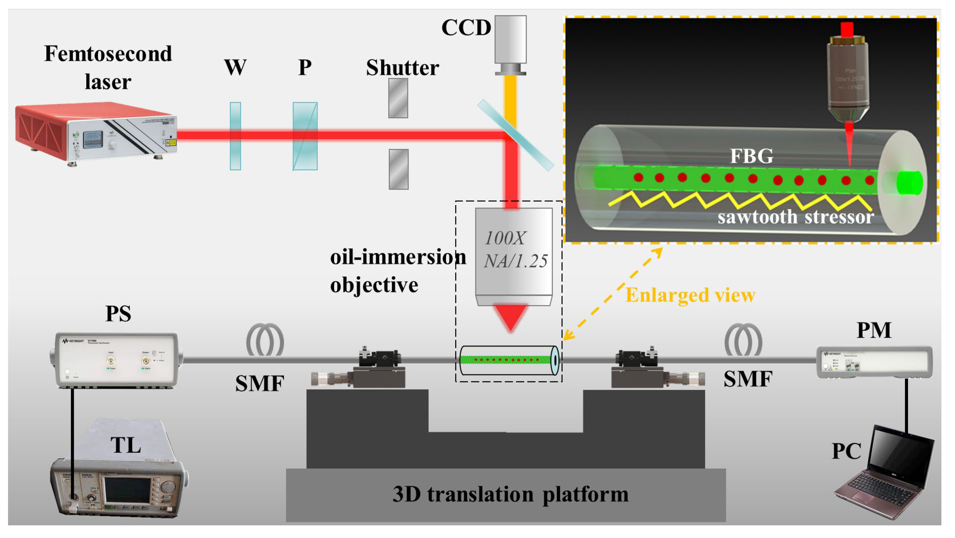
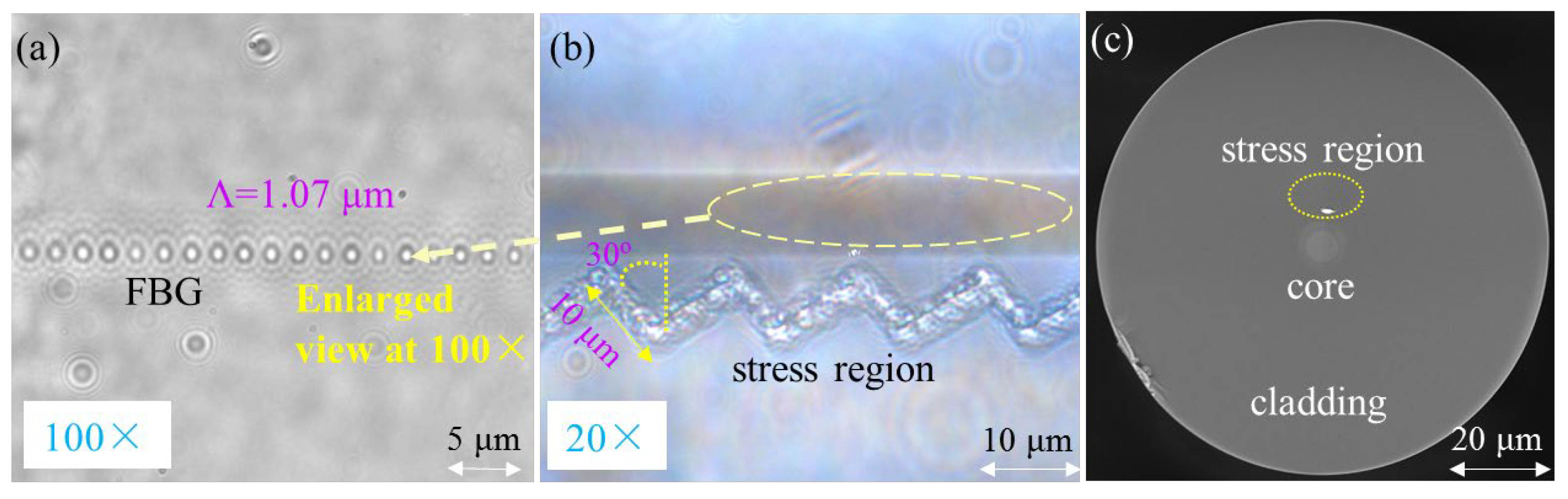
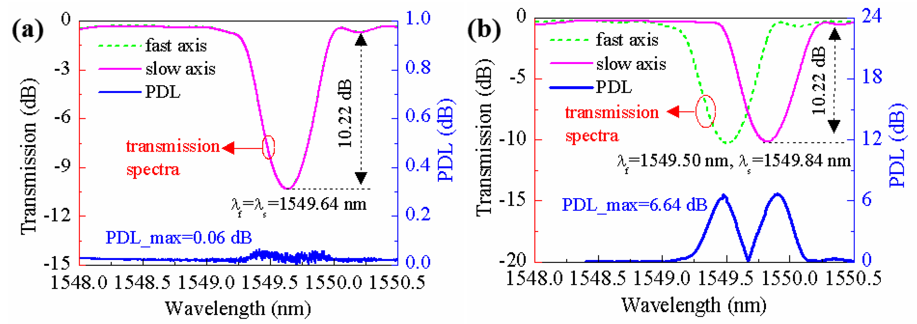
3. Preparation of Hi-Bi FBG Sensor

Figure 2 illustrates the principle and experimental setup used for fabricating the Hi-Bi FBG. First, a femtosecond (fs) laser with a central wavelength of 800 nm, a pulse duration of 100 fs, and a repetition rate of 1 kHz is employed to inscribe the FBG using point-by-point (PbP) technology. To prevent thermal drift, the laser is allowed to warm up for 30 min before the experiments, and repetition rate stability is verified using a photodiode and oscilloscope. The FBG period can easily be tuned by controlling the fs laser pulse frequency and velocity of fiber movement during the inscription process [25]. The scanning speed is controlled via custom LabVIEW 2024 Q1 software that synchronizes stage movement with laser pulse triggering, which can ensure uniform pulse-to-pulse spacing and consistent energy deposition per unit length. The selected single-mode fiber (SMF) is fixed on a high-precision displacement stage and the key parameters of SMF are listed in Table 1. The femtosecond laser is focused onto the fiber core using a 100× oil immersion objective with a numerical aperture (NA) of 1.25. The focused spot size must be sufficiently small to ensure that the fabricated FBG has high resolution and precision. The laser pulse energy can be precisely adjusted by rotating a half-wave plate (W) followed by a Glan polarizer (P). Before each writing session, pulse energy is calibrated using a thermal power meter to ensure consistency within ±1%. A CCD camera is used to monitor the laser fabrication process. The exposure time is controlled by a PC-driven mechanical shutter.
First, we employ the femtosecond laser PbP method to fabricate the FBG into the single-mode fiber. According to the pre-designed grating period and length, the fiber is moved at a speed of 1.07 μm/s (i.e., a grating period of 1.07 μm) via the displacement stage, allowing the femtosecond laser to successively irradiate different positions on the fiber. The relationship between the scanning speed (v), pulse repetition rate ffre, and FBG period (Λ) is clarified with an equation: Λ = v/ffre. Each irradiation can induce a refractive index change at the corresponding point in the fiber core. The FBG can easily be fabricated under the operating conditions of a femtosecond laser with a single-pulse energy of 30 μJ and a power of 30 mW. From the micrograph of the FBG, it is clear that the period of the FBG is 1.07 µm under 100× objective, as shown in Figure 3a. When the FBG is finished, the FBG is translated at a speed of v = 0.05 mm/s along a sawtooth path. As a result, a sawtooth stressor is inscribed in the fiber cladding near the FBG under 20× objective, as shown in Figure 3b. It is clear the sawtooth stressor has a track length of S = 10 μm, and a tilted angle of θ = 30°. Therefore, the sawtooth stressor exhibits a height of H = 8.7 μm and a pitch of W = 10.0 μm, respectively. Figure 3c demonstrates a cross-sectional image of the Hi-Bi FBG that was captured using a scanning electron microscope. It can be seen that there is a distinct stress region near the fiber core.
In the experiment, a tunable laser (TL), polarization synthesizer (PS), and optical power meter (PM) are adopted for the real-time monitoring of polarization-resolved transmission spectra and polarization-dependent loss (PDL) of the Hi-Bi FBG using Mueller matrices. Figure 4a shows that the transmission spectrum depth of the FBG with a grating length of 4 mm is approximately 10.22 dB, and the corresponding reflectivity is greater than 90%. It can be seen that the central wavelengths of the FBG at the fast and slow axes almost completely overlap before inducing the sawtooth stressor in the fiber cladding, i.e., λf = λs = 1549.64 nm. The PDL spectrum of the FBG is nearly flat, with a maximum value of about 0.06 dB. Moreover, the transmission spectrum depth of the FBG at fast and slow axes exhibits hardly any change, but the transmission spectra of the Hi-Bi FBG at two axes are separated, i.e., the central wavelengths of the fast and the slow axes are about 1549.50 nm and 1549.84 nm, respectively. According to Ref. [29], the PDL can be defined as the maximum change in the transmitted power for all possible states of polarization. Hence, it significantly increases as the resonance wavelengths for the eigen polarization modes become separated. As a result, it is obvious that the PDL of the FBG could be increased up to ~6.64 dB after inducing a sawtooth stressor in fiber cladding, as shown in Figure 4b. The fiber birefringence in the Hi-Bi FBG can be calculated from wavelength difference (i.e., λd = 0.34 nm) using Equations (1) and (2). A maximum birefringence of 2.97 × 10⁻⁴ is obtained, which could be comparable to that of commercial polarization-maintaining fibers. Therefore, the magnitude of the birefringence of the optical fiber can be regulated through the femtosecond laser direct writing scheme. This method is also applicable to other types of single-mode optical fibers, such as germanium-doped optical fibers or other photosensitive optical fibers.

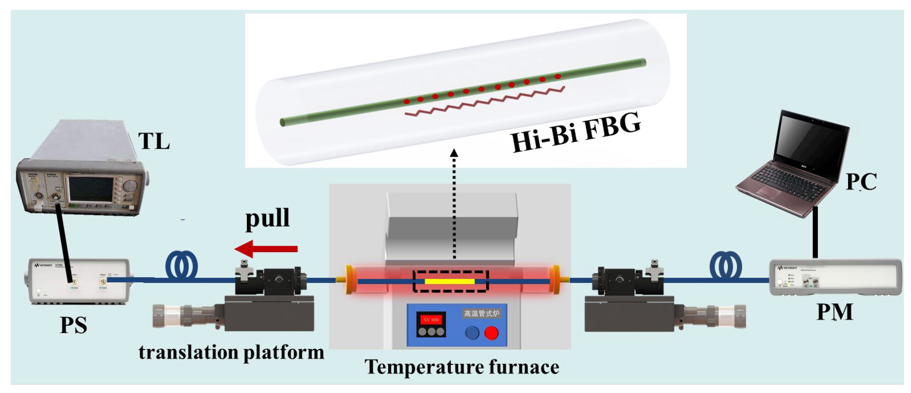
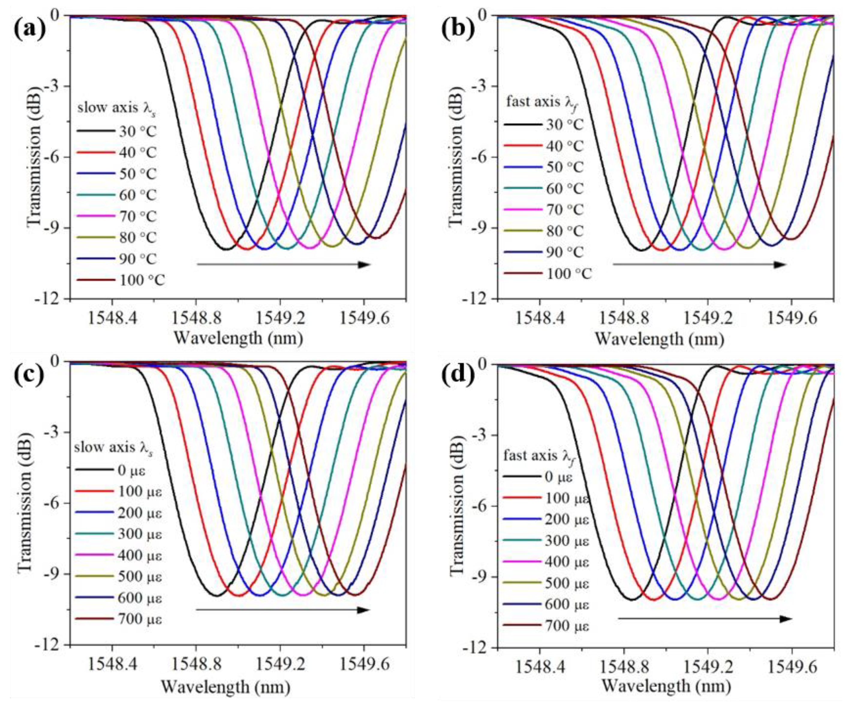
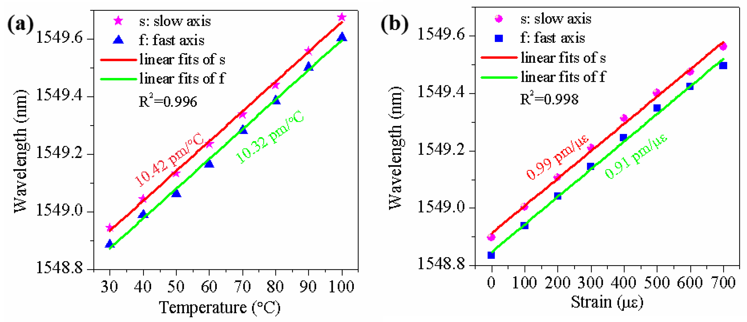
4. Simultaneous Measurement of Temperature and Strain

Figure 5 demonstrates the experimental setup for testing strain and temperature, which consists of a fast-scanning tunable laser source (TL), a polarization synthesizer (PS), and an optical power meter (PM). The optical signal output from the TL first passes through the polarization analyzer and then the Hi-Bi FBG. The polarization analyzer monitors the polarization state of the tunable laser after it has gone through the Hi-Bi FBG, and then the signal is directed to the optical power meter for real-time monitoring of power changes [22]. The transmission spectra of two orthogonal polarization modes (i.e., fast axis and slow axis) are measured via Mueller matrixes. The Hi-Bi FBG is placed in a temperature furnace in which the temperature can be precisely controlled. The fiber is fixed using two fiber holders, one of which is bonded to a fixed stage, with the other bonded to a high-precision displacement stage.
Subsequently, the temperature and static strain responses of the Hi-Bi FBG can be investigated by monitoring the wavelength shifts in the slow axis λs and fast axis λf. The temperature furnace is set to range from 30 to 100 °C, in 10 °C increments. Similarly to previous reports, including Refs. [7,26], each temperature test point is maintained for 5 min which is sufficiently long to acquire reliable spectral data. Figure 6a,b show the change in the transmission spectrum of the Hi-Bi FBG at two axes under zero strain. It is observed that the resonance wavelengths of both the slow and fast axes exhibit a red shift phenomenon with the strain increase, while there is minimal change in the depth of the transmission spectrum. Moreover, the static strain is applied to the Hi-Bi FBG by moving the high-precision displacement stage in range from 0 to 700 με in 100 με increments. As shown in Figure 6c,d, the transmission spectral changes in the Hi-Bi FBG at both axes with different temperatures under room temperature (about 25 °C) exhibit similar experimental phenomena.
Figure 7a shows the relationships between the resonant wavelength of the Hi-Bi FBG and the temperatures at the slow axis λs and fast axis λf. The measured results are well fitted by linear curves, and the resonant wavelength shifts in the Hi-Bi FBG at the fast and slow axes exhibit good linear characteristics in response to the temperature. The temperature sensitivities of the fast and slow axes are 10.32 pm/°C and 10.42 pm/°C, with linearity factors (R2) above 0.996. Moreover, the relationships between the resonant wavelength shifts in the Hi-Bi FBG and the strain are shown in Figure 7b, while the strain sensitivities of the fast and slow axes are 0.91 pm/µε and 0.99 pm/µε, both with linearity factors (R2) above 0.998. These linearity factors of the Hi-Bi FBG temperature sensor may be influenced by several factors, such as the temperature field distribution inside the temperature furnace, the power stability of the broadband light source, and the uniformity of the refractive index of the optical fiber material. As a result, we can obtain the second-order matrix as follows:
K = K ε f K T f K ε s K T s = 0.91 10.32 0.99 10.42 ,
Moreover, the variations in temperature and strain, ΔT and Δε, can be simultaneously determined by solving the matrix equation as follows:
Δ ε Δ T = 1 0.735 10.42 10.32 0.99 0.91 Δ λ f Δ λ s ,
In our experiment, we utilize the polarization-resolved wavelength demodulation technique to interrogate the Hi-Bi FBG sensor, achieving a resolution of 2 pm, which has a sampling resolution of 2 pm. As a result, the accuracy of this proposed sensor in measuring strain and temperature is estimated to be 2.2 µε and 0.2 °C. The measured accuracy might be related to the residual stress inside the Hi-Bi FBG, the resolution of the demodulator and environmental noise. If the Hi-Bi FBG is packaged to avoid external environmental noise interference and the residual stress inside it is removed, the accuracy of this proposed sensor can be further improved using a demodulator with higher resolution and signal-processing algorithms (i.e., the wavelength peak-seeking algorithm). Table 2 lists several types of single FBGs designed for simultaneous strain and temperature sensing. The sensitivity of the proposed Hi-Bi FBG is nearly comparable to that reported in the literature. To our knowledge, the Hi-Bi FBG we are currently using has several advantages, including low cost, compact size, straightforward preparation, and promising potential for significant improvements in multi-parameter sensing applications.

5. Conclusions

In summary, we present a dual-parameter sensor for temperature and strain that utilizes a single Hi-Bi FBG created through femtosecond laser direct writing technology. By monitoring the wavelength shifts in the fast and slow axes of the Hi-Bi FBG, we can simultaneously measure temperature and strain. The temperature sensitivities of the fast and slow axes are 10.32 pm/°C and 10.42 pm/°C, with linearity factors (R2) above 0.996, while the strain sensitivities are 0.91 pm/µε and 0.99 pm/µε, with linearity factors (R2) above 0.998. The accuracy of this proposed sensor in measuring strain and temperature is estimated to be 2.2 µε and 0.2 °C, respectively. This method can solve the problem of cross-sensitivity between temperature and strain, and it offers some advantages of low cost, compact size, and promising significant advancements in the practical multi-parameter sensing applications.

Author Contributions

Conceptualization, K.G. and H.W. (Hao Wu); methodology, Y.L. (Yonghao Liang); software, F.Z.; validation, H.W. (Hao Wu), Y.L. (Yonghao Liang) and M.S.; formal analysis, R.C.; data curation, K.G.; writing—original draft preparation, K.G.; writing—review and editing, K.G.; funding acquisition, H.W. (Hongcheng Wang) and Y.L. (Ye Liu). All authors have read and agreed to the published version of the manuscript.

Funding

This research was funded by the National Key R&D Program of China (Grant No. 2023YFC2206500); Guangdong Provincial Key Laboratory of Advanced Particle Detection Technology (Grant No. 2024B1212010005); Guangdong Basic and Applied Basic Research Foundation (Grant Nos. 2022A1515140143, 2023A1515011899); Dongguan Social Development Technology Program (Grant No. 20231800913352); and Open Project of Guangxi Key Laboratory of Nuclear Physics and Nuclear Technology under Grant NLK2022-10.

Institutional Review Board Statement

Not applicable.

Informed Consent Statement

Not applicable.

Data Availability Statement

All data that support the findings of this study are included within the article.

Conflicts of Interest

The authors declare no conflicts of interest.

References

  1. Rao, Y.J. In-fibre Bragg grating sensors. Meas. Sci. Technol. 1997, 8, 355. [Google Scholar] [CrossRef]
  2. Gan, W.; Li, X.; Wang, Y.; Wulamu, A.; Zhang, C.; Chen, X. Gas pipeline leakage detection and location by using w-FBG array based micro-strain sensing technology. Meas. Sci. Technol. 2024, 35, 056108. [Google Scholar] [CrossRef]
  3. Zhang, H.; Liu, T.; Lu, J.; Lin, R.; Chen, C.; He, Z.; Cui, S.; Liu, Z.; Wang, X.; Liu, B.; et al. Static and ultrasonic structural health monitoring of full-size aerospace multi-function capsule using FBG strain arrays and PSFBG acoustic emission sensors. Opt. Fiber Technol. 2023, 78, 103316. [Google Scholar] [CrossRef]
  4. Li, C.; Li, J.; Luo, C.; Xu, Q.; Wan, X.; Yang, L. Diagnosis and monitoring of tunnel lining defects by using comprehensive geophysical prospecting and fiber bragg grating strain sensor. Sensors 2024, 24, 1749. [Google Scholar] [CrossRef] [PubMed]
  5. Guo, J.; Zhao, K.; Zhou, B.; Ning, W.; Jiang, K.; Yang, C.; Kong, L.; Dai, Q. Wearable and skin-mountable fiber-optic strain sensors interrogated by a free-running, dual-comb fiber laser. Adv. Opt. Mater. 2019, 7, 1900086. [Google Scholar] [CrossRef]
  6. Ji, L.; Sun, Q.; Zhao, S.; Yang, S.; Xu, J.; Su, J.; Wu, C. High-resolution fiber grating pressure sensor with in-situ calibration for deep sea exploration. Opt. Express 2023, 31, 10358–10367. [Google Scholar] [CrossRef]
  7. Guo, K.; He, J.; Shao, L.; Xu, G.; Wang, Y. Simultaneous Measurement of Strain and Temperature by a Sawtooth Stressor-Assisted Highly Birefringent Fiber Bragg Grating. J. Light. Technol. 2020, 38, 2060–2066. [Google Scholar] [CrossRef]
  8. Su, D.; Qiao, X.; Chen, F.; Bao, W. Compact Dual Fiber Bragg Gratings for Simultaneous Strain and High-Temperature Measurement. IEEE Sens. J. 2019, 19, 5660–5664. [Google Scholar] [CrossRef]
  9. Wu, H.; Lin, Q.; Jiang, Z.; Zhang, F.; Li, L.; Zhao, L. A temperature and strain sensor based on a cascade of double fiber Bragg grating. Meas. Sci. Technol. 2019, 30, 065104. [Google Scholar] [CrossRef]
  10. Liang, J.; Yu, Y.; Bian, Q.; Xu, W.; Wang, Z.; Zhang, S.; Weng, J.; Zhu, J.; Chen, Y.; Hu, X.; et al. Metal-coated high-temperature strain optical fiber sensor based on cascaded air-bubble FPI-FBG structure. Opt. Express 2023, 31, 16795–16811. [Google Scholar] [CrossRef]
  11. Gao, X.; Ning, T.; Zhang, C.; Xu, J.; Zheng, J.; Lin, H.; Li, J.; Pei, L.; You, H. A dual-parameter fiber sensor based on few-mode fiber and fiber Bragg grating for strain and temperature sensing. Opt. Commun. 2020, 454, 124441. [Google Scholar] [CrossRef]
  12. Bian, Q.; Podhrazsky, A.; Bauer, C.; Stadler, A.; Buchfellner, F.; Kuttler, R.; Jakobi, M.; Volk, W.; Koch, A.W.; Roths, J. Temperature and external strain sensing with metal-embedded optical fiber sensors for structural health monitoring. Opt. Express 2022, 30, 33449–33464. [Google Scholar] [CrossRef]
  13. Zhu, M.; Murayama, H.; Wada, D.; Kageyama, K. Dependence of measurement accuracy on the birefringence of PANDA fiber Bragg gratings in distributed simultaneous strain and temperature sensing. Opt. Express 2017, 25, 4000–4017. [Google Scholar] [CrossRef] [PubMed]
  14. Tian, Q.; Xin, G.; Lim, K.; He, Y.; Liu, J.; Ahmad, H.; Liu, X.; Yang, H. Cascaded Fabry-Perot interferometer-regenerated fiber Bragg grating structure for temperature-strain measurement under extreme temperature conditions. Opt. Express 2020, 28, 30478–30488. [Google Scholar] [CrossRef] [PubMed]
  15. Zhu, J.; He, W.; Li, S.; Li, Z.; Zhu, L. Temperature and strain simultaneous sensing measurement based on an all-fiber Mach-Zehnder interferometer and fiber Bragg grating. Appl. Opt. 2023, 62, 6661–6671. [Google Scholar] [CrossRef] [PubMed]
  16. Patrick, H.; Williams, G.; Kersey, A.; Pedrazzani, J.; Vengsarkar, A. Hybrid fiber Bragg grating/long period fiber grating sensor for strain/temperature discrimination. IEEE Photon. Technol. Lett. 1996, 8, 1223–1225. [Google Scholar] [CrossRef]
  17. James, S.; Dockney, M.; Tatam, R. Simultaneous independent temperature and strain measurement using in-fibre Bragg grating sensors. Electron. Lett. 1996, 32, 1133–1134. [Google Scholar] [CrossRef]
  18. Guan, B.O.; Tam, H.Y.; Chan, H.L.W.; Choy, C.L.; Demokan, M.S. Discrimination between strain and temperature with a single fiber Bragg grating. Microw. Opt. Technol. Lett. 2002, 33, 200–202. [Google Scholar] [CrossRef]
  19. Cavaleiro, P.; Araujo, F.; Ferreira, L.; Santos, J.; Farahi, F. Simultaneous measurement of strain and temperature using Bragg gratings written in germanosilicate and boron-codoped germanosilicate fibers. IEEE Photon. Technol. Lett. 1999, 11, 1635–1637. [Google Scholar] [CrossRef]
  20. Li, X.; Duan, T.; Wang, R.; Chen, F.; Qiao, X. Ultrahigh return loss LPFGs fabricated via femtosecond laser direct writing of ultrashort TFBGs. Opt. Lett. 2025, 50, 2053–2056. [Google Scholar] [CrossRef]
  21. Li, X.; Wang, J.; Chen, F.; Qiao, X. Femtosecond laser direct writing tilted fiber Bragg gratings in multicore fiber. Opt. Lett. 2024, 49, 6984–6987. [Google Scholar] [CrossRef] [PubMed]
  22. Zhao, R.; Lu, X.; Gao, C.; Ye, X.; Li, H.; Wu, B.; Wang, M. Highly localized FBG fabricated by femtosecond laser single-pulse filaments. Opt. Laser Technol. 2025, 187, 112810. [Google Scholar] [CrossRef]
  23. Gao, S.; Liu, Y.; Yang, J.; Duan, Z.; Yin, T. Ultrasensitive refractive sensor based on femtosecond laser inscribed long-period fiber grating with a few microcavities. J. Light. Technol. 2023, 42, 1696–1701. [Google Scholar] [CrossRef]
  24. Xiao, K.; Zan, Y.; Ouyang, Y.; Fei, S.; Hu, Z.; Fang, L.; Chen, Q. Low-loss and tight-bend waveguides via multiple scans of a femtosecond laser. Opt. Lett. 2025, 50, 1449–1452. [Google Scholar] [CrossRef]
  25. Guo, K.; He, J.; Li, H.; Xu, B.; Lu, S.; Liu, S.; Wang, Y. High-spatial-resolution high-temperature sensor based on ultra-short fiber Bragg gratings with dual-wavelength differential detection. J. Light. Technol. 2021, 40, 2166–2172. [Google Scholar] [CrossRef]
  26. Guo, K.; Yang, R.; Wang, H.; Zhou, F.; Chu, R.; Wang, H.; Liu, Y. Ultrashort Fiber Optic Temperature Sensor for the Small-Scale Heat Sources. IEEE Sens. J. 2023, 24, 2682–2688. [Google Scholar] [CrossRef]
  27. Zhu, Y.; Miao, Z.; Wu, Z.; Shi, C.; Deng, G.; Zhang, H.; Zhou, S. Thulium doped all-fiber laser based on a double-cladding Bragg grating via femtosecond laser plane-by-plane writing technology. Opt. Express 2025, 33, 2386–2394. [Google Scholar] [CrossRef]
  28. Xu, B.; He, J.; Xu, X.; He, J.; Guo, K.; Bao, W.; Wang, Y. Simultaneous measurement of torsion and strain at high temperature by using a highly birefringent cladding fiber Bragg grating. Opt. Express 2022, 30, 28710–28719. [Google Scholar] [CrossRef]
  29. Oh, S.; Han, W.; Paek, U.; Chung, Y. Discrimination of temperature and strain with a single FBG based on the birefringence effect. Opt. Express 2004, 12, 724–729. [Google Scholar] [CrossRef]
  30. Pashaie, R.; Mirzaei, A.; Vahedi, M.; Shokrieh, M. Discrimination between the strain and temperature effects of a cantilever beam using one uniform FBG sensor. Opt. Quant. Electron. 2023, 55, 114. [Google Scholar] [CrossRef]
Figure 1. A schematic diagram of the sensing principles of the Hi-Bi FBG.
Photonics 12 00502 g001
Figure 2. Schematic diagram of the experimental setup for fabricating the Hi-Bi FBG.
Photonics 12 00502 g002
Figure 3. Microscope images of the FBG and sawtooth stressor under 100× (a) and 20× (b) objective. (c) The cross-sectional view images of the Hi-Bi FBG.
Photonics 12 00502 g003
Figure 4. Evolutions of transmission spectra and PDL spectra of the FBG (a) and Hi-Bi FBG (b).
Photonics 12 00502 g004
Figure 5. Experimental setup for the Hi-Bi-FBG temperature and strain test.
Photonics 12 00502 g005
Figure 6. Transmission spectra changes in the Hi-Bi FBG at two axes under different temperatures (a,b) and strains (c,d).
Photonics 12 00502 g006
Figure 7. Resonant wavelength of the Hi-Bi FBG at both axes vs. the temperature (a) and strain (b).
Photonics 12 00502 g007
Table 1. The key parameters of single-mode fiber.
ParameterValue
Core diameter10.0 ± 0.1 μm
Cladding diameter125.0 ± 0.5 μm
GeO₂ doping concentration in core3.2 mol%
Refractive Index (Core)1.468
Table 2. The comparison of a few types of single FBG.
Fabrication MethodSensor StructureFiber TypeDemodulation
Method
BTemperature SensitivityStrain
Sensitivity
Fs laser direct writing
technology [28]
Hi-Bi CFBGSMFOFDR2.8 × 10−4NA1.06 pm/μɛ
UV laser phase mask and fs laser direct writing [7]FBG + stressorSMFWavelength and wavelength difference demodulation2.96 × 10−49.57 pm/°C1.25 pm/μɛ
UV laser phase mask [29]FBGphotosensitive SMFWavelength and PDL demodulation4 × 10−611 pm/°C1.11 pm/μɛ
UV laser phase mask [30]uniform FBGphotosensitive SMFWavelength and FWHW demodulationNA14.4 pm/°C0.84 pm/μɛ
UV laser phase mask [13]Panda-FBGPMFOFDR8.87 × 10−412.07 pm/°C1.27 pm/μɛ
Fs laser direct writing
technology in this work
FBG + stressorSMFWavelength Demodulation 2.97 × 10−410.42 pm/°C0.99 pm/μɛ
Disclaimer/Publisher’s Note: The statements, opinions and data contained in all publications are solely those of the individual author(s) and contributor(s) and not of MDPI and/or the editor(s). MDPI and/or the editor(s) disclaim responsibility for any injury to people or property resulting from any ideas, methods, instructions or products referred to in the content.

