Article

Development and Characterization of an Asymmetric MZI Temperature Sensor Using Polymer Waveguides for Extended Temperature Measurement Scopes

1
Institute for Future, School of Automation, Qingdao University, Qingdao 266071, China
2
School of Physical Sciences, Qingdao University, Qingdao 266071, China
*
Author to whom correspondence should be addressed.
Photonics 2025, 12(5), 491; https://doi.org/10.3390/photonics12050491
Submission received: 2 April 2025 / Revised: 2 May 2025 / Accepted: 8 May 2025 / Published: 15 May 2025

Abstract

:
To meet diverse industrial needs, temperature sensors with a wide measurement range have become a key element. In this paper, we propose an asymmetric Mach–Zehnder interferometer (MZI) temperature sensor based on polymer optical waveguides. Experimental results show that the output interference signal exhibits periodic changes with temperature variations. The device exhibits a temperature measurement range of 120 °C and a sensitivity of 0.27 rad/°C. This study provides an effective new approach for developing high-performance, low-cost temperature sensors suitable for an extended temperature measurement range.

1. Introduction

Integrated optical waveguides have demonstrated distinct advantages in the field of temperature sensing due to their miniaturization, high integration density, excellent stability, immunity to electromagnetic interference, low power consumption, and scalability [1,2,3,4]. Commonly employed structures include Mach–Zehnder interferometers (MZIs) [5], grating structures [6], ring resonators [7], slot waveguides [8], and surface plasmon resonance structures [9]. Among these, the MZI has been extensively utilized in temperature sensing [10,11,12] due to its simple configuration [13], ease of integration [14], excellent stability [15], and broad material compatibility.
Temperature sensors based on MZI waveguides typically realize temperature sensing by measuring the phase difference between their upper and lower arms or the wavelength shifts caused by dispersion effects [16,17,18]. Lee et al. employed an MZI waveguide structure utilizing the opposite thermo-optic properties of SiO2 and TiO2, achieving a temperature sensitivity as high as 340 pm/°C within a measurement range of 25–35 °C [19]. Ding et al. proposed a cascaded dual-MZI configuration based on silicon waveguide chips, leveraging the Vernier effect for phase-superposition amplification, thereby significantly enhancing temperature change response and attaining a sensitivity of 1753.7 pm/°C within a range of 27–67 °C [20]. Payne et al. introduced an MZI structure with heterogeneous integration of silicon and silicon nitride, exploiting the substantial thermo-optic coefficient difference between these materials to achieve a sensitivity of 324 pm/°C in a measurement range of 9.7 °C [21]. The aforementioned MZI-based temperature sensors predominantly utilize silicon material systems, capitalizing on silicon’s high thermo-optic coefficient to deliver superior sensitivity and high integration density [22]. However, in the ongoing search for optical waveguide materials with more diverse functionalities and broader application potential, polymer-based materials have been attracting attention [23,24,25,26].
Although polymeric materials are not yet employed as extensively as silicon, their ease of processing, low loss, and low cost have made them a research hotspot in waveguide materials, and they are particularly well-suited for temperature sensor fabrication [27,28,29]. Moreover, polymers possess relatively high thermo-optic coefficients, effectively magnifying the optical signals induced by temperature changes and thereby significantly boosting sensor performance [30]. Niu et al. designed an asymmetric polymer waveguide MZI by introducing waveguides of different widths to accumulate phase differences, thereby enhancing temperature-sensing sensitivity. A sensitivity of 30.8 nm/°C was achieved over a measurement range of 25–28 °C [31]. Chen et al. employed two-photon polymerization (TPP) to fabricate an asymmetric polymer waveguide MZI structure. By introducing interferometer arms of distinct dimensions and packaging the device with a temperature-sensitive material, they enhanced the sensing sensitivity to approximately 2.01 nm/°C in the 30–70 °C range [32]. Guan et al. proposed an asymmetric MZI structure formed by hybridizing silicon waveguides with SU-8 polymer, utilizing SU-8 as the waveguide core in one arm and exploiting the out-of-phase thermo-optic responses of SU-8 and silicon to achieve a sensitivity of 172 pm/°C within 20–45 °C [33]. Similarly, Gao et al. employed materials with opposing thermo-optic coefficients and introduced an asymmetric PMMA–SiO2 hybrid waveguide MZI structure, achieving a sensitivity of 6.85 nm/°C within the 0–3 °C measurement range [34]. These temperature sensors, with an operating range of a few degrees up to several tens of degrees Celsius, exhibit high sensitivity and have laid a solid foundation for the development of polymer-based waveguide temperature sensors.
In this paper, an asymmetric MZI structure based on polymer waveguides was designed to achieve both high sensitivity and a broad measurement range for temperature sensing. By exploiting the high thermo-optic coefficient of polymeric materials and the length disparity between the two arms, the phase shift efficiency was effectively enhanced. Moreover, because the primary measurement parameter is the temperature-dependent phase shift, the sensor offers a comparatively wide measurement range without the need for a costly optical spectrum analyzer, markedly reducing overall costs and demonstrating substantial potential for practical applications. The sensor studied here, with its excellent performance and wide temperature adaptability stemming from the innovative design that exploits the high thermo-optic coefficient of polymeric materials and the length disparity between the two arms, effectively meets the monitoring needs in both biomedical and industrial scenarios. Whether it is the 50–98 °C range for biomedical heating or the 90–110 °C range for industrial overheating warnings, the sensor offers broad application prospects and practical value.

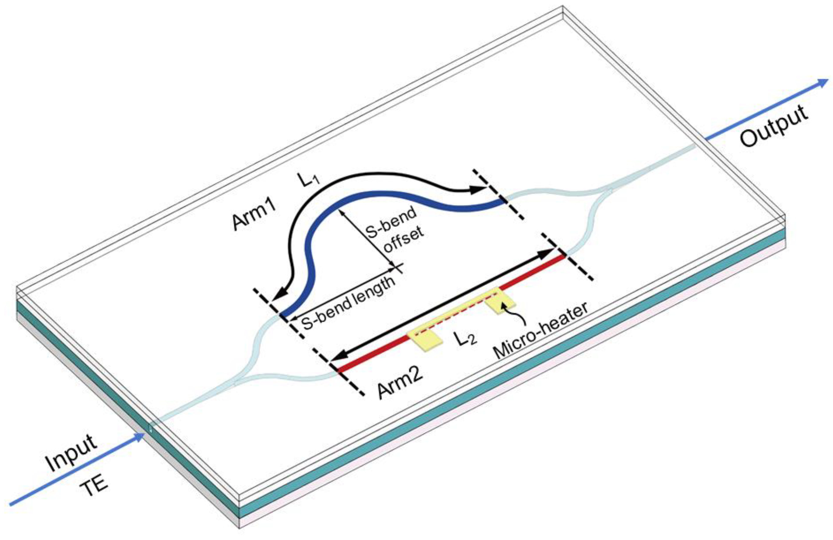
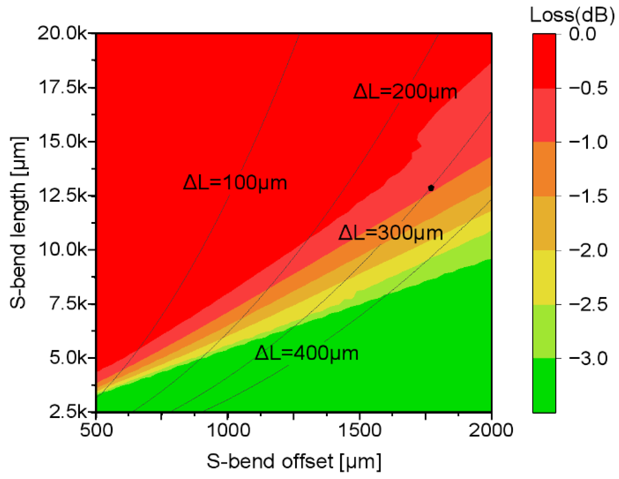
2. Operating Principle and Device Design

The structure of the proposed temperature sensor based on polymer waveguides is shown in Figure 1. The upper arm (Arm 1) is composed of two identical S-bend waveguides, whose total length L 1 depends on the S-bend offset and length. In contrast, Arm 2 is a straight waveguide with length L 2 , creating an optical path length difference ( L 1 L 2 = Δ L ) between the two arms. This difference creates the conditions for a phase shift between the two arms induced by ambient temperature changes. When a transverse electric-polarized (TE) mode is launched, the Y-branch splits the incident light equally into both arms, with each traveling a distinct optical path. As a result, the temperature-dependent phase variation caused by the optical path length difference leads to periodic interference signals in the output light signal.
In order to accurately verify the interference performance of the MZI, a Cr–Au micro-heater was integrated. This Cr–Au micro-heater was meticulously integrated above Arm 2 of the MZI. By applying thermal power to it, high-precision regulation and control of the local temperature can be achieved. This precise temperature control can further cause a change in the effective refractive index of optical waveguide Arm 2, thus enabling flexible and effective adjustment of the phase difference between the two arms of the MZI. This provides a reliable experimental method for in-depth exploration and verification of the interference performance of the MZI.
During the temperature measurement process, the refractive indices of all material layers are influenced by the surrounding temperature. This dependency can typically be described using a linear model, as presented in Equation (1):
n = n 0 + d n d T · Δ T
In the above equation, n 0 and n represent the refractive indices at the initial temperature and after a temperature change, respectively. The parameter d n d T is the thermal optic coefficient (TOC), and Δ T denotes the temperature variation. A change in temperature directly influences the refractive indices of the waveguide layers, resulting in a corresponding shift in the effective refractive index. Because each layer’s refractive index varies linearly with temperature, the effective refractive index also exhibits an approximately linear response.
In an asymmetric MZI structure, when the temperature changes by Δ T , the phase difference Δ φ between the two arms is mainly governed by the length mismatch and the change in the effective refractive index. Its expression is given by the following:
Δ φ = 2 π λ Δ n e f f ( L 1 + b · L 1 · Δ T ) ( L 2 + b · L 2 · Δ T ) = 2 π λ Δ n e f f Δ L ( 1 + b Δ T )
In the above expression, Δ n e f f denotes the change in the effective refractive index due to the temperature variation Δ T . The parameter b is the thermal expansion coefficient, L 1 and L 2 are the lengths of the upper and lower MZI arms, respectively, and λ is the operating wavelength. The sensor’s temperature sensitivity S is defined as the rate of change of the phase difference Δ φ with respect to temperature T :
S = d Δ φ d T = 2 π λ [ d Δ n e f f d T Δ L 1 + b Δ T + Δ n e f f d Δ L 1 + b Δ T d T ]
In Equation (3), because the silicon substrate serves as a rigid carrier with an extremely low thermal expansion coefficient (approximately 2 ppm/°C) and a high elastic modulus, it provides robust in-plane confinement for the spin-coated polymer layer. Although the chosen polymer exhibits a relatively large thermal expansion coefficient (around 350 ppm/°C), its inherent tendency to expand freely when heated is strongly suppressed in-plane, leading primarily to the accumulation of internal stress rather than any significant dimensional change. As a result, the phase variation caused by thermal expansion is substantially smaller than that induced by the thermo-optic effect (i.e., refractive index change). Hence, the length-change term can be neglected (i.e., b Δ T 0 ), and the temperature sensitivity can be simplified as follows:
S = d Δ φ d T 2 π λ [ d Δ n e f f d T Δ L ]
To fabricate the asymmetric MZI temperature sensor, ZPU and LFR polymer materials from Chemoptics Co., Ltd. (Daejeon, Republic of Korea) with refractive indices of 1.43 and 1.395 at 1550 nm were employed for the core and cladding layers, respectively. Both ZPU and LFR exhibit exceptional thermo-optic properties, characterized by coefficients of −1.8 × 10⁴ and −2.5 × 10⁴, respectively, providing high sensitivity to temperature-induced variations in the refractive index. This high sensitivity makes them ideal candidates for optical waveguide temperature sensing applications. Furthermore, both materials demonstrate low propagation losses (<0.1 dB/cm) at 1550 nm, which is crucial for minimizing signal energy loss and ensuring the accuracy of sensor performance. However, polymer materials typically suffer from poor thermal stability at elevated temperatures, which may lead to potential losses. To mitigate this issue, this study integrates ZPU and LFR with differing thermo-optic coefficients, thereby dynamically enhancing the refractive index difference between the core and cladding layers. This modification improves signal confinement and reduces optical loss at high temperatures.
To generate an optical path length difference between the two arms of the MZI, two S-bend structures were implemented in one of the arms. The S-bend offset refers to the offset distance between the output and the input of the S-bend, in the direction perpendicular to the light propagation direction. The S-bend length represents the distance between the input and the output of the S-bend in the light propagation direction, as illustrated in Figure 1. An increase in the S-bend offset means a smaller radius of the bend, while an increase in the S-bend length means a larger radius of the bend. As we know, the size of the bend radius directly determines the degree of bending loss. Therefore, in this design, the two parameters of S-bend offset and S-bend length jointly determine the magnitude of the loss of the S-bend. To accurately evaluate the propagation loss introduced by both the S-bend offset and S-bend length, we performed simulations using the 2D beam propagation method (BPM); the simulation results are shown in Figure 2. The length difference ΔL between Arm 1 and Arm 2 is determined by different parameter configurations, which is represented by the black contour lines in Figure 2. When light passes through the S-bend structure, it will undergo varying degrees of attenuation. Different colors in the figure correspond to different attenuation intervals. Through the analysis of various combinations of S-bend offset and S-bend length, we identified the region where the loss is less than −1 dB, which is highlighted in red. To ensure low loss less than −1 dB while maximizing the length difference between Arm 1 and Arm 2 of the MZI, a path difference of 300 µm was selected for the experiments, with an S-bend offset of 1750 µm and an S-bend length of 12,500 µm.

3. Fabrication of the Integrated Optic Temperature Sensor

The proposed polymer waveguide-based integrated optical temperature sensor was fabricated using ZPU143 and LFR1395 materials from Chemoptics Co., Ltd. (Daejeon, Republic of Korea) through planar lightwave circuit (PLC) technology. The fabrication procedure is schematically presented in Figure 3. A lower cladding layer of LFR1395 with a thickness of 10 μm was formed on a silicon wafer by spin-coating and UV curing. After coating a photoresist layer on the LFR1395 layer, a core waveguide pattern was formed through a photolithography process and oxygen plasma etching. The cladding layer was etched to a depth of 1.45 μm to satisfy the single-mode waveguide condition. Then, 4.1 μm of ZPU143 was coated over the etched cladding layer as a core layer. A cladding of LFR1395 was coated and cured, and then Cr–Au was deposited to form a micro-heater with a width of 40 μm through a second photolithography process and wet etching to finish the device.

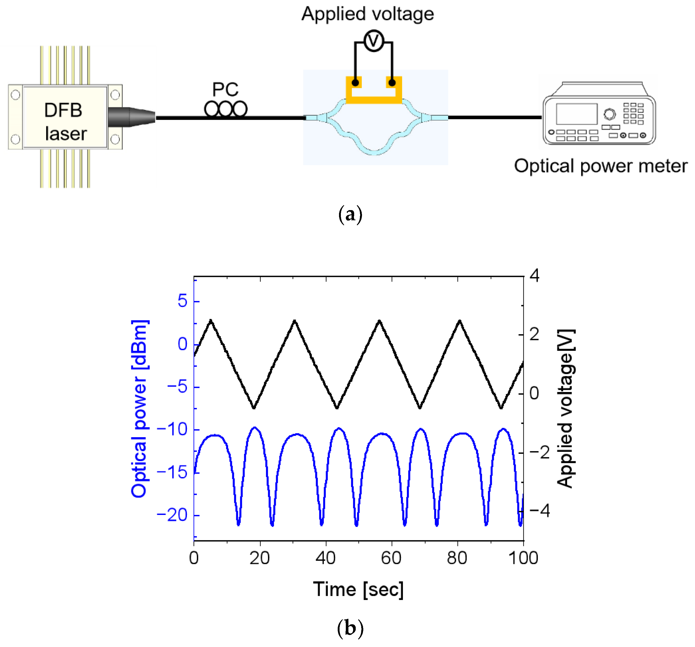
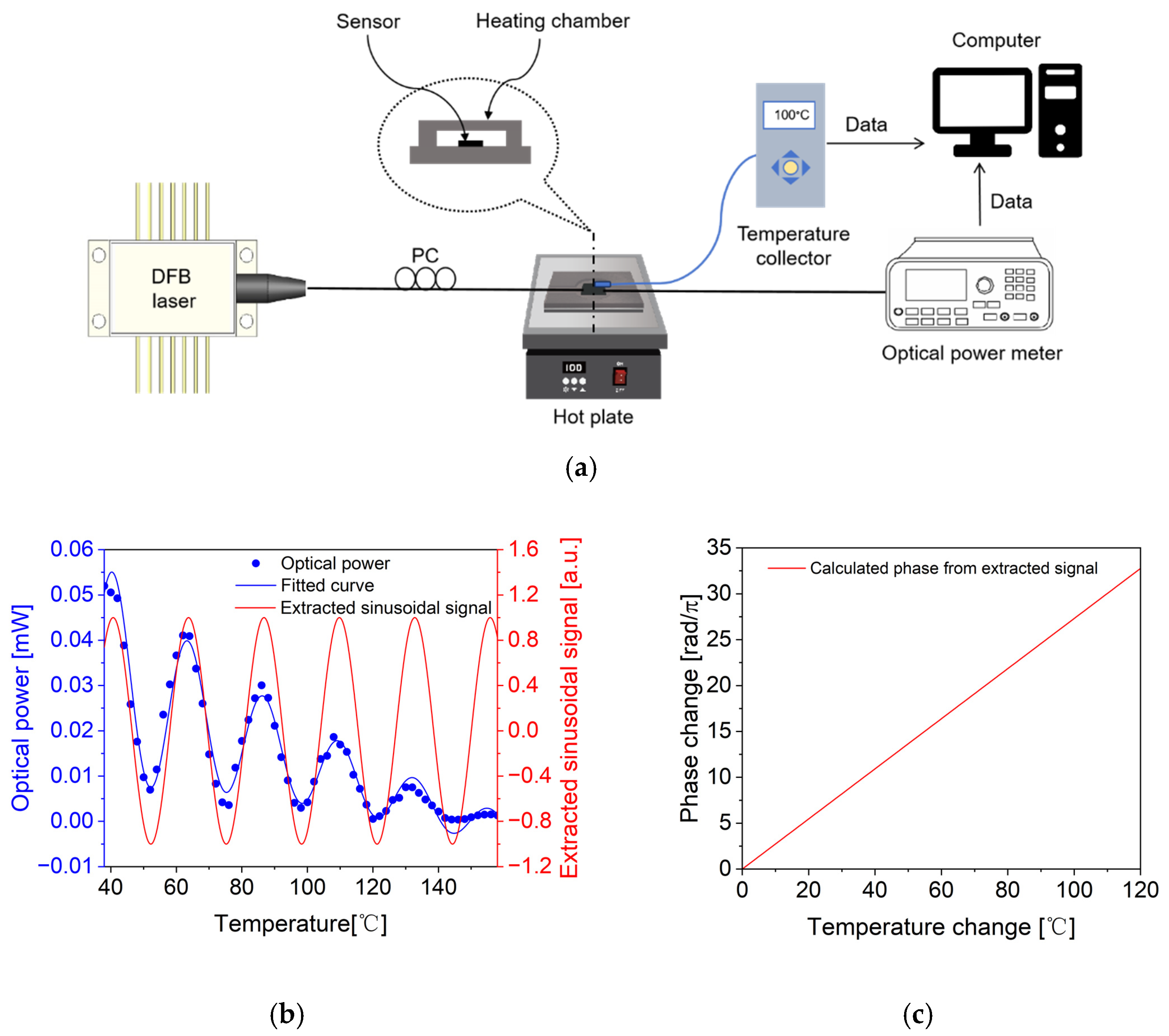
4. Characterization of the Fabricated Device

Before measuring the performance of the temperature sensor, to ensure that the MZI has effective interference performance, devices such as a distributed feedback (DFB) laser, a polarization controller, a function signal generator, and an optical power meter were used for testing; the measurement setup is shown in Figure 4a. By applying a triangular voltage waveform to the electrode on one of the MZI arms, the refractive index of the polymer material decreases, creating a phase difference between the two arms that produces the output interference signal, as shown in Figure 4b. It can be observed that the interference signal exhibits obvious periodic variations, and the extinction ratio of the signal can reach over 10 dB, thus verifying the interference characteristics of the device.
To measure the characteristics of the fabricated temperature sensor, devices such as a DFB laser, a polarization controller, a hotplate with a heating chamber, a temperature collector, and an optical power meter were used; the measurement setup is shown in Figure 5a. The sensor was placed inside a partially sealed heating chamber, with a PT100 temperature probe from Taizhou Chuangmei Instrument Technology Co., Ltd. (Taizhou, China) affixed to the sensor surface to monitor its temperature. To ensure an exact one-to-one correspondence between the output power and the corresponding temperature, and to bring the measurement environment temperature to a stable state, we set the initial measurement temperature higher than the ambient temperature. After careful consideration, we selected 38 °C as the starting point for the measurement. However, despite setting the initial temperature in this way, it should be noted that the actual lower limit of the operating temperature of the polymer optical waveguide is much lower than 38 °C. The input polarization was adjusted to the TE mode. During measurement, the chamber temperature was increased from 38 °C to 158 °C, while the surface temperature and output optical power were recorded at 2 °C intervals using the PT100 probe and an optical power meter, respectively. When the temperature changes, a phase difference is generated between the upper and lower arms of the sensor, resulting in an interference signal at the output port. Thus, the relationship between the optical power and the temperature can be obtained, as shown in Figure 5b. From the temperature-dependent optical output power (blue dot) in Figure 5b, it can be observed that the output power exhibits an exponentially decreasing sinusoidal variation with increasing temperature, although some signal attenuation occurs. Under the influence of a high-temperature environment, the degree of freedom of movement of the internal molecular chains of the polymer increases significantly. Since the forces such as van der Waals forces between the molecular chains are not sufficient to maintain its stable solid-state structure at high temperatures, the physical form of the polymer begins to change. Starting from the initial solid state with a certain shape-holding ability, it gradually transforms into a soft and deformable state, and its ability to resist external forces and deformation is significantly reduced. It is as if it gradually “melts” under high temperatures and becomes easy to knead and deform. Therefore, the losses generated in the high-temperature environment during this experiment mainly include the following aspects. Firstly, the glue that bonds the chip to the fiber block loses part of its original adhesive force and fixing performance due to expansion and softening, resulting in coupling losses at the input and output ends. Secondly, due to the poor high-temperature stability of the polymer, the losses generated by the S-bend structure increase with the rise in temperature. In addition, the temperature sensor is composed of various different materials, leading to the occurrence of thermal drift. Finally, the light caused by the coupling losses and S-bend losses forms interference signals at the output end, and the occurrence of destructive interference is also one of the reasons for the reduction in output power. By fitting the measured optical intensity data and extracting the sinusoidal component (as shown by the red curve in Figure 5b), the phase change induced by temperature can be derived. A temperature sensitivity of 0.27 rad/°C was obtained, as presented in Figure 5c. When compared with the theoretical temperature sensitivity of 0.23 rad/°C, which was calculated by utilizing Equation (4) in Section 2, the device demonstrates a slightly higher sensitivity.
Table 1 compares the results of this work with those of recent publications on silicon and polymer waveguide-based asymmetric MZI temperature sensors. The comparison covers the materials, device structure, sensitivity, sensing range, and measurement metric. Compared with references [31,32,33,34], the measurement metric differs, which prevents a direct performance comparison. However, the measurable range clearly shows that our device performs significantly better than the others. In reference [35], two materials, silicon and silicon nitride (SiN), were used, with the phase change as the measurement metric. However, it achieved only a small measurement range of up to 10 °C. In comparison, this work utilizes LFR and ZPU series polymer materials, achieving a significantly wider measurement range of 120 °C and excellent sensitivity of 0.27 rad/°C with an arm length difference of only 300 µm, offering a broader measurement range and higher sensitivity. However, judging from the measurement results of the optical power meter, the optical power shows the same values at several temperature points, which undoubtedly increases the difficulty of accurately determining the temperature. To address this issue, our proposed solution is to install a mini thermoelectric cooler (TEC) device at the bottom of the sensor based on the actual ambient temperature. By driving the TEC device, the chip temperature can be maintained at a specific value and will not change with the ambient temperature. This is also a common method used to ensure the operating temperature of optical communication devices. We can use the TEC to adjust the output power to half of the maximum output power and set this position as the initial phase position. When we need to measure the ambient temperature, we can turn off the TEC. If the output power increases, it indicates that the phase difference is increasing, meaning the temperature is rising. If the output power decreases, it indicates that the phase difference is decreasing, meaning the temperature is dropping. In addition, without using the TEC, this temperature sensor can also be applied in fields where only the temperature changes are of concern.
In summary, in the application of temperature sensors, compared with silicon-based materials, although polymer materials have advantages such as low cost, high flexibility, and ease of processing, they also have disadvantages and many challenges. The thermal stability of polymer materials is relatively poor, and their performance will decline at high temperatures, which limits their application in high-temperature scenarios. In addition, the stability of their optical properties is insufficient, and they are easily affected by external factors, which may affect the measurement accuracy and stability of the temperature sensors. The main challenges they face are improving their thermal stability to operate stably within a wider temperature range, enhancing the stability of their optical properties, and reducing external interference, so as to ensure the accuracy and reliability of the temperature sensors.

5. Conclusions

An asymmetric MZI temperature sensor based on polymer optical waveguides was demonstrated. To achieve low loss and high phase shift, the length difference Δ L between the two arms of the MZI was set to 300 µm. When the TE mode is input, light is split evenly into the upper and lower arms through a Y-branch and experiences different optical paths. The temperature-related phase changes caused by the optical path difference induce periodic interference signals in the output light. Although the output power exhibits a sinusoidal variation with increasing temperature, signal attenuation is observed. This is due to the significant loss of the S-bend in the MZI structure, and the light that emerges from the waveguide forms a plane waveguide mode, generating interference signals at the output end. Additionally, high temperatures cause the UV adhesive between the ends of the fiber array and the temperature sensor to expand, reducing the coupling efficiency. As a result, when the measurement range exceeds 120 °C, the interference signal disappears. By fitting the optical intensity signals collected within the 120 °C range and extracting the sinusoidal components, phase changes were calculated based on the extracted sinusoidal signal. This yielded a temperature sensitivity of 0.27 rad/°C.

Author Contributions

Conceptualization, F.L. and G.H.; methodology, F.L. and G.H.; simulation, X.Z. and T.W.; writing—original draft preparation, F.L.; writing—review and editing, F.L. and G.H. All authors have read and agreed to the published version of the manuscript.

Funding

This work was supported by the National Key Research and Development Project (grant No. 2020YFB1313604) of the National Natural Science Foundation of China.

Institutional Review Board Statement

Not applicable.

Informed Consent Statement

Not applicable.

Data Availability Statement

The original contributions presented in the study are included in the article. Further inquiries can be directed to the corresponding author.

Conflicts of Interest

The authors declare no conflicts of interest.

References

  1. Jiao, H.; Qing, C.; Li, X.; Sun, D.; Wang, L.; Zhou, Y.; Wang, K.; Feng, L. Hybrid Integrated Optical Transceiver for Interferometric Fiber-Optic Sensors. IEEE Sens. J. 2024, 24, 10188–10195. [Google Scholar] [CrossRef]
  2. Yao, N.; Wang, S. Recent Progress of Optical Tactile Sensors: A Review. Opt. Laser Technol. 2024, 176, 111040. [Google Scholar] [CrossRef]
  3. Lu, Q.; Wang, Y.; Wang, X.; Yao, Y.; Wang, X.; Huang, W. Review of Micromachined Optical Accelerometers: From Mg to Sub-Μg. Opto-Electron. Adv. 2021, 4, 200045–1–200045-24. [Google Scholar] [CrossRef]
  4. Zhou, J.; Wang, Y.; Zhang, G.-J. State-of-the-Art Strategies of Surface Plasmon Resonance Biosensors in Clinical Analysis: A Comprehensive Review. Coord. Chem. Rev. 2024, 520, 216149. [Google Scholar] [CrossRef]
  5. Bruck, R.; Melnik, E.; Muellner, P.; Hainberger, R.; Lämmerhofer, M. Integrated Polymer-Based Mach-Zehnder Interferometer Label-Free Streptavidin Biosensor Compatible with Injection Molding. Biosens. Bioelectron. 2011, 26, 3832–3837. [Google Scholar] [CrossRef]
  6. Chen, J.; Liu, B.; Zhang, H. Review of Fiber Bragg Grating Sensor Technology. Front. Optoelectron. 2011, 4, 204–212. [Google Scholar] [CrossRef]
  7. Zhang, Z.; Wang, Y.; Wang, J.; Yi, D.; Chan, D.W.U.; Yuan, W.; Tsang, H.K. Integrated Scanning Spectrometer with a Tunable Micro-Ring Resonator and an Arrayed Waveguide Grating. Photonics Res. 2022, 10, A74–A81. [Google Scholar] [CrossRef]
  8. Wang, Y.; Zhong, L.; Lau, K.Y.; Han, X.; Yang, Y.; Hu, J.; Firstov, S.; Chen, Z.; Ma, Z.; Tong, L. Precise Mode Control of Laser-Written Waveguides for Broadband, Low-Dispersion 3D Integrated Optics. Light Sci. Appl. 2024, 13, 130. [Google Scholar] [CrossRef]
  9. Wang, Q.; Ren, Z.-H.; Zhao, W.-M.; Wang, L.; Yan, X.; Zhu, A.; Qiu, F.; Zhang, K.-K. Research Advances on Surface Plasmon Resonance Biosensors. Nanoscale 2022, 14, 564–591. [Google Scholar] [CrossRef]
  10. El Shamy, R.S.; Khalil, D.; Swillam, M.A. Mid Infrared Optical Gas Sensor Using Plasmonic Mach-Zehnder Interferometer. Sci. Rep. 2020, 10, 1293. [Google Scholar] [CrossRef]
  11. Xiong, C.; Liao, C.; Li, Z.; Yang, K.; Zhu, M.; Zhao, Y.; Wang, Y. Optical Fiber Integrated Functional Micro-/Nanostructure Induced by Two-Photon Polymerization. Front. Mater. 2020, 7, 586496. [Google Scholar] [CrossRef]
  12. Chatzianagnostou, E.; Manolis, A.; Dabos, G.; Ketzaki, D.; Miliou, A.; Pleros, N.; Markey, L.; Weeber, J.-C.; Dereux, A.; Chmielak, B.; et al. Scaling the Sensitivity of Integrated Plasmo-Photonic Interferometric Sensors. ACS Photonics 2019, 6, 1664–1673. [Google Scholar] [CrossRef]
  13. Su, H.; Zhao, C.; Song, X.; Kong, F.; Zhang, Z.; Liu, C. High-Sensitivity Optical Fiber Temperature Sensor with Cascaded Configuration of MZI and FPI Based on Vernier Effect. Opt. Fiber Technol. 2021, 67, 102751. [Google Scholar] [CrossRef]
  14. Peng, C.; Yang, C.; Zhao, H.; Liang, L.; Zheng, C.; Chen, C.; Qin, L.; Tang, H. Optical Waveguide Refractive Index Sensor for Biochemical Sensing. Appl. Sci. 2023, 13, 3829. [Google Scholar]
  15. Han, J.; Wu, X.; Ge, X.; Xie, Y.; Song, G.; Liu, L.; Yi, Y. Highly Sensitive Liquid M-Z Waveguide Sensor Based on Polymer Suspended Slot Waveguide Structure. Polymers 2022, 14, 3967. [Google Scholar] [CrossRef]
  16. Zhao, C.; Xu, L.; Liu, L. Ultrahigh Sensitivity Mach-Zehnder Interferometer Sensor Based on a Weak One-Dimensional Field Confinement Silica Waveguide. Sensors 2021, 21, 6600. [Google Scholar] [CrossRef]
  17. Ma, Y.; Nghia, N.-H.; Zhou, J.; Maeda, H.; Wu, Q.; Eldlio, M.; Pistora, J.; Cada, M. Mach-Zehnder Interferometer-Based Integrated Terahertz Temperature Sensor. IEEE J. Sel. Top. Quantum Electron. 2017, 23, 4601607. [Google Scholar] [CrossRef]
  18. Guo, J.; Yang, C.; Dai, Q.; Kong, L. Soft and Stretchable Polymeric Optical Waveguide-Based Sensors for Wearable and Biomedical Applications. Sensors 2019, 19, 3771. [Google Scholar] [CrossRef]
  19. Lee, J.-M. Ultrahigh Temperature-Sensitive Silicon MZI with Titania Cladding. Front. Mater. 2015, 2, 36. [Google Scholar] [CrossRef]
  20. Ding, Z.; Dai, D.; Shi, Y. Ultra-Sensitive Silicon Temperature Sensor Based on Cascaded Mach–Zehnder Interferometers. Opt. Lett. 2021, 46, 2787–2790. [Google Scholar] [CrossRef]
  21. Payne, D.A.; Matthews, J.C. A CMOS-Compatible Heterogeneous Interferometer for Chip-Scale Temperature Sensing. Appl. Phys. Lett. 2022, 121, 261104. [Google Scholar] [CrossRef]
  22. Zegadi, R.; Ziet, L.; Zegadi, A. Design of High Sensitive Temperature Sensor Based on Two-Dimensional Photonic Crystal. Silicon 2020, 12, 2133–2139. [Google Scholar] [CrossRef]
  23. Liu, J.; Zhang, Z. Polymer-Embedding Germanium Nanostrip Waveguide of High Polarization Extinction. Polymers 2023, 15, 4093. [Google Scholar] [CrossRef]
  24. Xie, Y.; Chen, L.; Li, H.; Yi, Y. Polymer and Hybrid Optical Devices Manipulated by the Thermo-Optic Effect. Polymers 2023, 15, 3721. [Google Scholar] [CrossRef]
  25. Pudleiner, T.; Hoinkis, J.; Karnutsch, C. Analysis of Diffracted Mode Outcoupling in the Context of Amplified Spontaneous Emission of Organic Thin Films. Polymers 2024, 16, 1950. [Google Scholar] [CrossRef]
  26. Khan, Y.; Butt, M.A.; Khonina, S.N.; Kazanskiy, N.L. Thermal Sensor Based on Polydimethylsiloxane Polymer Deposited on Low-Index-Contrast Dielectric Photonic Crystal Structure. Photonics 2022, 9, 770. [Google Scholar] [CrossRef]
  27. Leal-Junior, A.; Frizera-Neto, A.; Marques, C.; Pontes, M.J. A Polymer Optical Fiber Temperature Sensor Based on Material Features. Sensors 2018, 18, 301. [Google Scholar] [CrossRef]
  28. Mieloszyk, M.; Majewska, K.; Andrearczyk, A. Embedded Optical Fibre with Fibre Bragg Grating Influence on Additive Manufactured Polymeric Structure Durability. Materials 2022, 15, 2653. [Google Scholar] [CrossRef]
  29. Lakard, B.; Carquigny, S.; Segut, O.; Patois, T.; Lakard, S. Gas Sensors Based on Electrodeposited Polymers. Metals 2015, 5, 1371–1386. [Google Scholar] [CrossRef]
  30. Oh, M.-C.; Chu, W.-S.; Shin, J.-S.; Kim, J.-W.; Kim, K.-J.; Seo, J.-K.; Lee, H.-K.; Noh, Y.-O.; Lee, H.-J. Polymeric Optical Waveguide Devices Exploiting Special Properties of Polymer Materials. Opt. Commun. 2016, 362, 3–12. [Google Scholar] [CrossRef]
  31. Niu, D.; Wang, L.; Xu, Q.; Jiang, M.; Wang, X.; Sun, X.; Wang, F.; Zhang, D. Ultra-Sensitive Polymeric Waveguide Temperature Sensor Based on Asymmetric Mach–Zehnder Interferometer. Appl. Opt. 2019, 58, 1276–1280. [Google Scholar] [CrossRef] [PubMed]
  32. Chen, M.-Q.; Lin, Z.-Y.; Zhao, Y. Femtosecond Laser Direct-Writing On-Chip MZI Temperature Sensor Based on Polymer Waveguides. IEEE Trans. Instrum. Meas. 2023, 72, 7007508. [Google Scholar] [CrossRef]
  33. Guan, X.; Wang, X.; Frandsen, L.H. Optical Temperature Sensor with Enhanced Sensitivity by Employing Hybrid Waveguides in a Silicon Mach-Zehnder Interferometer. Opt. Express 2016, 24, 16349–16356. [Google Scholar] [CrossRef] [PubMed]
  34. Gao, Z.; Du, Y.; Zhang, Q.; Qin, Y.; Fang, J.; Yi, Y. Silica–Polymer Heterogeneous Hybrid Integrated Mach–Zehnder Interferometer Optical Waveguide Temperature Sensor. Polymers 2024, 16, 2297. [Google Scholar] [CrossRef]
  35. Dullo, F.T.; Sokolov, V.; Chauvet, C.; Lindecrantz, S.; Solbø, S.A.; Hellesø, O.G. Temperature Sensitivity of Waveguide Mach-Zehnder Interferometer. In Proceedings of the Integrated Optics: Devices, Materials, and Technologies XVIII, San Francisco, CA, USA, 3–5 February 2014; SPIE: Bellingham, WA, USA, 2014; Volume 8988, pp. 419–426. [Google Scholar]
Figure 1. Schematic diagram of the asymmetric MZI-based temperature sensor employing polymer waveguides.
Photonics 12 00491 g001
Figure 2. Distribution of optical loss in the S-bend waveguide structure as a function of different S-bend offsets and lengths. Black line depicts length difference (ΔL) between two arms of MZI.
Photonics 12 00491 g002
Figure 3. Fabrication process of the asymmetric MZI waveguide temperature sensor.
Photonics 12 00491 g003
Figure 4. (a) Measurement setup for interference performance test of MZI. (b) Optical interference signals (Blue line) measured by applying a triangular voltage waveform (Black line) to the electrode on one of the MZI arms.
Photonics 12 00491 g004
Figure 5. (a) Experimental setup for measuring the temperature response of the sensor. (b) Temperature-dependent optical output power as a function of exponentially decreasing sine signal (blue dot). A sinusoidal signal (red line) extracted from the fitted curve (blue line). (c) Phase variation obtained from the extracted sinusoidal signal as a function of temperature change.
Photonics 12 00491 g005
Table 1. Comparison of temperature sensors based on silicon and polymer materials.
Ref.MaterialsYearStructureSensitivity
(rad/°C or nm/°C)
Sensing Range (°C)Measurement
Metric
[31]NOA, M-20002019Asymmetric
MZI
30.8 nm/°C3Wavelength
[32]IP-S, PDMS2023Asymmetric
MZI
2.01 nm/°C40Wavelength
[33]Silicon, SU-82016Asymmetric
MZI
0.172 nm/°C25Wavelength
[34]PMMA, NOA
SU-8
2024Asymmetric
MZI
6.85 nm/°C3Wavelength
[35]Silicon, SiN2014Asymmetric
MZI
0.262 rad/°C10Phase
This workLFR, ZPU2025Asymmetric
MZI
0.27 rad/°C120Phase
Disclaimer/Publisher’s Note: The statements, opinions and data contained in all publications are solely those of the individual author(s) and contributor(s) and not of MDPI and/or the editor(s). MDPI and/or the editor(s) disclaim responsibility for any injury to people or property resulting from any ideas, methods, instructions or products referred to in the content.

