Research on Large Divergence Angle Laser Ranging System †


Abstract
1. Introduction
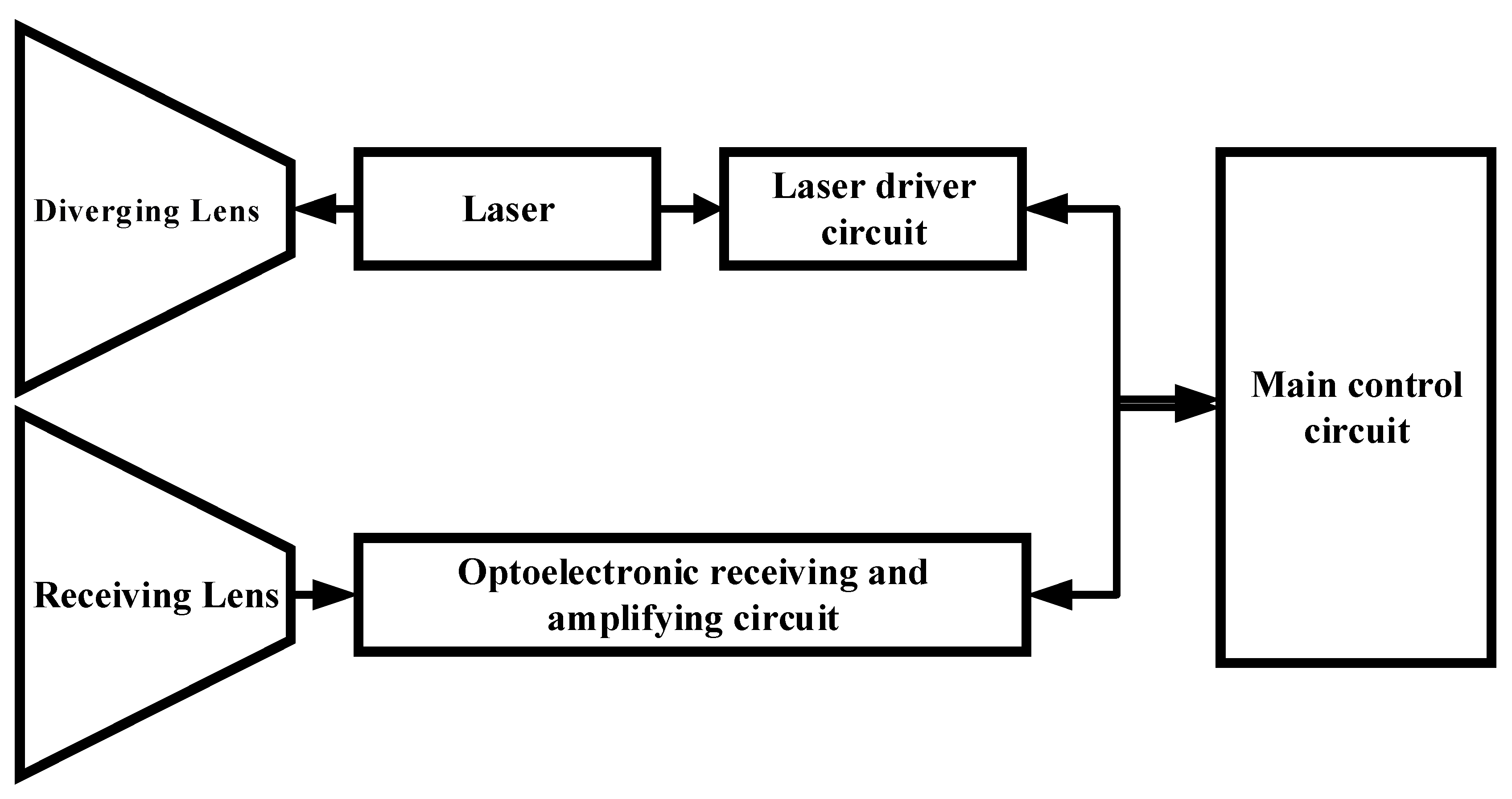
2. Overall Solution
3. Design of Large-Divergence Transmitter and Wide-Field-of-View (WFOV) Receiver Systems
3.1. Selection of Laser Source
3.2. Diverging Lens
3.3. Beam Quality Simulation of Diverging Lens Optical System
3.4. Design of Wide Field-of-View (WFOV) Optical Reception System for Laser Echo Detection
4. Experimental Results and Discussion
4.1. Laser Beam Divergence Angle Test
4.2. Ranging Capability Test
5. Results
Author Contributions
Funding
Institutional Review Board Statement
Informed Consent Statement
Data Availability Statement
Conflicts of Interest
References
- Wang, W.-B.; Wang, T.-F.; Guo, J. Analysis for opto-electrical acquisition tracking and pointing control technology on satellite. Chin. Opt. 2014, 7, 6. [Google Scholar]
- Jiang, H.-B. Selecting Optimum of Signal-to-Noise Ratio and Laser Beam Divergence for Laser Range-Finder. Opt. Optoelectron. Technol. 2023, 1, 1. [Google Scholar]
- Xiao, B. Methods for Laser Distance Measurement. Geospat. Inf. 2010, 4, 8. [Google Scholar]
- Chen, B.; Chen, Y.; Wang, G.-C. Recent Advance in Passive Q-switch of l.54 μm Er: Glass Laser. Opt. Optoelectron. Technol. 2004, 1, 2. [Google Scholar]
- Zhang, J.-J. Design of transmitting and receiving system for long-distance pulse laser ranging. Laser J. 2024, 11, 45. [Google Scholar]
- Yagiu, Y.; Kumazawa, T. New collimating lens systems for laser diode package. In Proceedings of the IEEE 43rd Electronic Components and Technology Conference, Orlando, FL, USA, 1–4 June 1993; Volume 43, pp. 1135–1138. [Google Scholar]
- Yan, Y.-B.; Wang, C.; Wu, M.-X.; Jin, G.-F. A binary optical element of laser diode for compensating astigmation and enhancing collimation. Infrared Laser Eng. 1996, 25, 5. [Google Scholar]
- Ji, J.-W.; Yang, S.-H. Research on Large Divergence Angle Laser Ranging System. In Proceedings of the 10th Symposium on Novel Optoelectronic Detection Technonlogy and Application, Taiyuan, China, 1–3 November 2024. [Google Scholar]
- Zhang, C.; Wang, X.-X.; Yan, G.-S. Optimum Design to a Single Lens Transmitted Collimating Module of Laser Ranging Finders. Laser Binfrared 2009, 39, 4. [Google Scholar]
- Wang, G. Design and study about field diaphragm of receiving optical system in a laser rangefinder. Laser Technol. 2014, 38, 5. [Google Scholar]
- ISO11146-1:2021; Lasers and laser-related equipment—Test methods for laser beam widths, divergence angles and beam propagation ratios. ISO: Geneva, Switzerland, 2021.
- Duan, H.-Z.; Luo, Y.-X.; Zhang, J.-Y. Inter-satellite laser interferometry. Acta Sci. Nat. Univ. Sunyatseni 2021, 60, 1–2. [Google Scholar]


| Serial Number | Parameter Name | Parameter Indicators |
|---|---|---|
| 1 | Wavelength | 1535 nm |
| 2 | Pulse width | ≤5 ns |
| 3 | Operating rate | 10 hz |
| 4 | Beam full divergence | 12.2 mrad |
| 5 | Weight | <10 g |
| 6 | Dimensions (W × H × L) | 25 mm × 8 mm × 7 mm |
| 7 | The diameter of the output light spot. | 0.35 mm |
| Parameters | Symbol | Test Conditions | Min | Typical | Max | Units |
|---|---|---|---|---|---|---|
| Wavelength Response | λ | - | 1000~1700 | nm | ||
| Active diameter | D | - | 500 | μm | ||
| Vop for specified responsivity | Vbr | dark current ID = 100 μA, optical powerφe = 0 | 30 | 70 | V | |
| Responsivity | RV | M = 10, λ = 1.55 μm, pulse widthTw = 100 ns; | 300 | KV/W | ||
| Outpoput impedance | Ro | VCC/VEE = ±5 V | - | 50 | Ω | |
| Positive supply current | ICC | - | 30 | mA | ||
| Negative supply current | IEE | - | 10 | mA | ||
| Output voltage swing | VO | - | 0.7 | V | ||
| DC output offset voltage | Voffset | - | 0 | V | ||
Disclaimer/Publisher’s Note: The statements, opinions and data contained in all publications are solely those of the individual author(s) and contributor(s) and not of MDPI and/or the editor(s). MDPI and/or the editor(s) disclaim responsibility for any injury to people or property resulting from any ideas, methods, instructions or products referred to in the content. |
© 2025 by the authors. Licensee MDPI, Basel, Switzerland. This article is an open access article distributed under the terms and conditions of the Creative Commons Attribution (CC BY) license (https://creativecommons.org/licenses/by/4.0/).
Share and Cite
Ji, J.; Yang, S.; Feng, Y. Research on Large Divergence Angle Laser Ranging System. Photonics 2025, 12, 482. https://doi.org/10.3390/photonics12050482
Ji J, Yang S, Feng Y. Research on Large Divergence Angle Laser Ranging System. Photonics. 2025; 12(5):482. https://doi.org/10.3390/photonics12050482
Chicago/Turabian StyleJi, Junwen, Suhui Yang, and Yimin Feng. 2025. "Research on Large Divergence Angle Laser Ranging System" Photonics 12, no. 5: 482. https://doi.org/10.3390/photonics12050482
APA StyleJi, J., Yang, S., & Feng, Y. (2025). Research on Large Divergence Angle Laser Ranging System. Photonics, 12(5), 482. https://doi.org/10.3390/photonics12050482