1. Introduction
Integrated time–frequency phase (TFP)-synchronization transmission is an emerging interdisciplinary technology developed to meet the stringent requirements of long-distance or ultra-long-distance measurement and control [
1,
2,
3,
4]. The ability to deliver high-precision and highly stable time, frequency, and phase synchronization signals is crucial in fields such as spatially distributed collaborative positioning systems, satellite navigation, and space exploration [
4]. In recent years, significant progress has been made in TFP-synchronization transmission technologies based on optical fiber links [
5,
6]. Research has demonstrated that ultra-stable optical frequency references can be transmitted in optical fiber networks, with frequency instabilities as low as 1.7 × 10
−14@1 s [
7], and improvements reaching 2 × 10
−17@1 s after compensation, while the uncertainty of 1 pulse per second (1 PPS) time signals can be reduced to 2.08 ps [
8]. However, these studies rely on fixed optical fiber network deployments [
1], making them unsuitable for complex terrains or mobile platforms like intelligent vehicular networks, stereoscopic coherent detection systems, or unmanned aerial vehicle (UAV) swarms [
9,
10,
11]. Therefore, free-space TFP-synchronization transmission technology has become a key solution to meet the needs of these scenarios.
Currently, practical free-space TFP-synchronization methods primarily use microwaves as carriers, but the improvement in synchronization accuracy is slow. As a result, recent studies focused on improving precision have often adopted optical methods [
12]. Moreover, existing research often focuses on synchronization accuracy metrics, neglecting the simultaneous requirement for high-speed communication [
13]. Additionally, research on achieving high-precision TFP synchronization using optoelectronic hybrid technology for one-to-many networking scenarios remains relatively scarce.
Based on the existing research background and application requirements,
Table 1 summarizes the differences in TFP-synchronization performance under fiber-optic communication, microwave communication, and FSO communication conditions, as well as their respective applicable scenarios.
To address these issues, this paper proposes an optoelectronic hybrid architecture for integrated TFP synchronization and communication transmission in free-space conditions. By combining the disturbance resistance of microwave systems with the high bandwidth advantages of optical systems, this architecture resolves the traditional trade-off between synchronization precision and communication speed [
14], achieving stable and high-precision synchronization at a data rate of 1.5 Gbps.
To verify the feasibility of this proposed architecture, a one-to-two main–auxiliary experimental platform consisting of four wide-angle laser communication electro-optical pods was set up. The symmetric free-space optical (FSO) link effectively mitigates the impact of long-term drift errors, significantly enhancing synchronization stability on dynamically moving platforms [
15,
16,
17,
18]. Each electro-optical pod terminal is equipped with an integrated signal and clock processing module, utilizing pseudo-code regeneration ranging (PCRR) technology [
19]. The clock and signals are modulated and demodulated via a field-programmable gate array (FPGA). This technology significantly improves synchronization accuracy and is particularly suitable for high-speed, low-latency, and interference-resistant remote communication applications, making it adaptable to UAV swarms and intelligent vehicular networks [
3,
20].
The remainder of this paper is structured as follows:
Section 2 details the fundamental principles of the proposed free-space TFP-synchronization transmission system, including coherent forwarding measurement methods, pseudo-code regeneration clock recovery principles, and dynamic phase synchronization adjustment mechanisms.
Section 3 presents a simulation-based analysis of the receiver-side time-phase synchronization error detection algorithm under typical channel conditions.
Section 4 outlines the setup and evaluates the performance of the integrated one-to-two main–auxiliary dynamic platform equipment in outdoor experimental conditions, with tests on data transmission rates, synchronization accuracy, and system stability. Finally,
Section 5 concludes the paper and discusses potential directions for future research.
2. Principles of TFP-Synchronization Transmission System
2.1. Principles of Coherent Forwarding Measurement
This system adopts a coherent forwarding-based regenerative pseudo-code measurement technique. By measuring the pseudo-code phase information, high-precision TFP-synchronization transmission is realized. The receiver utilizes the randomness of intra-frame data and maps the data demodulated after frame synchronization into a regenerated pseudo-code using a pseudo-code generation algorithm (e.g., Gold code or m-sequence). This pseudo-code is strictly aligned with the frame structure, ensuring the uniqueness and repeatability of the pseudo-code phase information for each frame. By re-correlating the regenerated pseudo-code with the delayed received data, the receiver achieves robust pseudo-code synchronization under low signal-to-noise ratio (SNR) conditions. The pseudo-code correlation can be calculated using the following equation:
where
c(
n) is the pseudo-code sequence,
τ is the delay, and
N is the pseudo-code length.
The preamble and synchronization word in the frame structure further enhance the reliability of pseudo-code acquisition and tracking, thereby reducing the probability of false synchronization. In addition, the introduction of multi-correlator channels allows the system to simultaneously detect multiple pseudo-code phases and select the phase with the highest correlation as the synchronization point, further improving synchronization accuracy. This method overcomes the limitation of unknown pseudo-code during code synchronization in traditional pseudo-code measurements, extends the integration time of the code tracking loop to a full frame, decouples the tight relationship between communication rate and measurement accuracy, effectively improves the SNR of the uplink signal, and enhances the effective power of the downlink signal, thereby supporting a higher measurement accuracy.
Figure 1 and
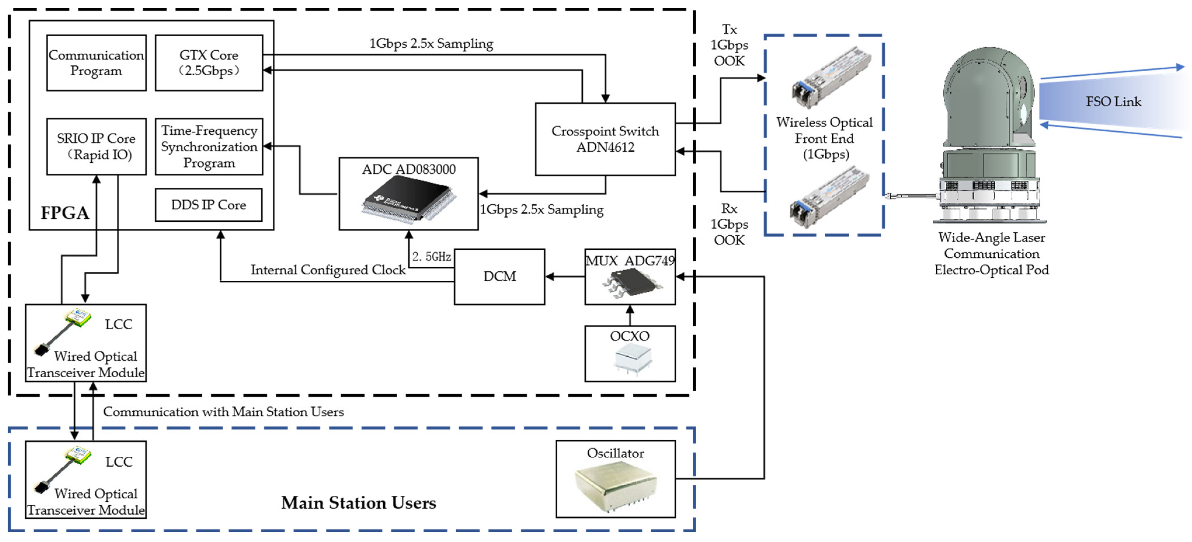
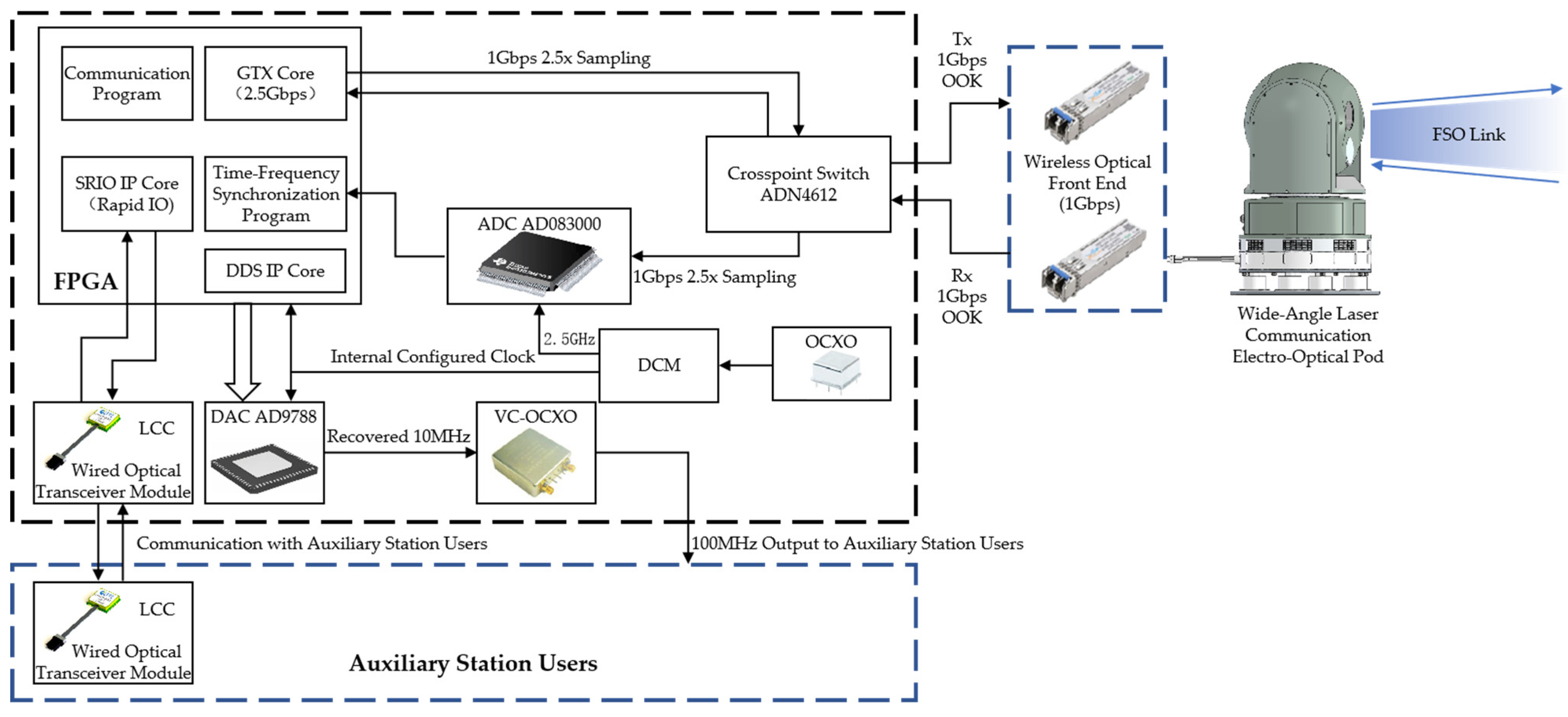
Figure 2 illustrate the system block diagrams of the main and auxiliary stations for TFP-synchronization transmission, respectively. Both systems are based on the principle of coherent forwarding measurement and adopt a symmetric FSO link architecture for bidirectional communication. The main station actively transmits synchronization signals containing time, frequency, and phase information along with user communication data, and performs ranging and phase difference extraction locally. The auxiliary station demodulates the received signal, recovers the clock, and modulates a regenerated pseudo-code before retransmitting it back to the main station, thus forming a closed-loop system. Both ends use wide-angle laser communication electro-optical pods as the spatial link front end, equipped with high-speed cameras and three-axis gimbals to realize automatic target tracking and link maintenance. The signal processing module consists of ADCs, DACs, FPGAs, and high-stability crystal oscillators, supporting 1.5 Gbps high-speed signal transmission and high-precision TFP synchronization. The integrated equipment is mounted on vehicle platforms, supporting one-to-many network communication.
The specific measurement process is as follows: the main station transmits a signal to the auxiliary station. After the auxiliary station performs signal acquisition, frame synchronization, and tracking operations, it uses the extracted pseudo-code phase information to locally recover a clock that is homologous with that of the main station and coherently forwards the signal back to the main station. Upon receiving the retransmitted signal, the main station again performs acquisition, frame synchronization, and tracking, and it extracts the pseudo-code phase information using a phase-locked loop (PLL) to obtain the high-precision pseudo-code chip phase offset between the main and auxiliary stations. It then generates a regenerated pseudo-code that is frequency- and phase-aligned with the main station’s clock, thereby realizing high-precision measurement. The time delay measurement value is calculated by
where Δ
φ is the pseudo-code chip phase difference, and
fc is the pseudo-code rate. Using this equation, the system can directly convert the chip phase difference into a time delay measurement value and eliminate relative clock deviations through bidirectional measurement, thereby achieving sub-chip-level high-precision measurement.
To measure the time delay
τ accurately, both the sending time
TM1 and receiving time
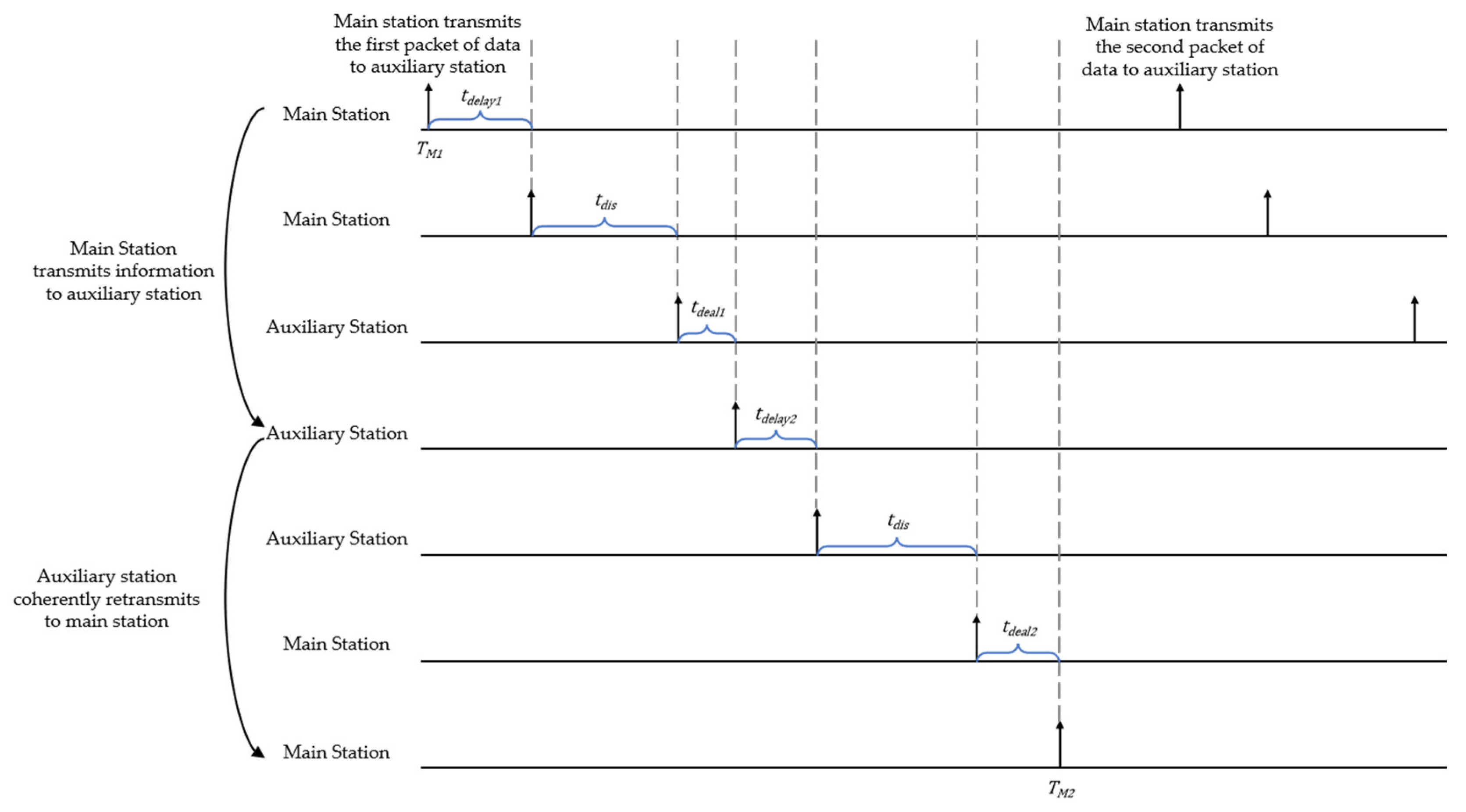
TM2 must be known. Since the main and auxiliary stations process signals based on their respective time references, the synchronized forwarding ranging principle enables both ends to eliminate time base differences by mutually exchanging signals. A complete measurement process is illustrated in
Figure 3, in which the spatial transmission delay of the signal between the main and auxiliary stations is denoted as
tdis.
The spatial transmission delay is calculated by Equation (3) as
where
tdelay1 and
tdelay2 are the signal transmission delays at the main and auxiliary station transmitters, both of which can be calibrated using self-detection measurements after powering on;
tdeal1 is the processing delay during coherent forwarding at the auxiliary station;
tdeal2 is the processing delay when the main station receives the returned signal, which can also be obtained through program timing analysis;
tdis is the spatial transmission delay;
TM2 denotes the main station’s receiving time; and
TM1 is the sending time at the main station.
2.2. Principle of Clock Recovery Based on Regenerated Pseudo-Code
The main station uses a 100 MHz reference clock as the basis to frame the source data and read the pseudo-code from the code table through FPGA, thereby modulating the TFP signal and data information. The modulated signal is then transmitted into free space via the laser transmitter. On the receiving side, the auxiliary station captures the signal through a photodetector, extracts the TFP parameters, restores a 100 MHz clock synchronized with the main station, and transmits the user information to the auxiliary station’s user terminal. The clock recovery process and principle based on regenerated pseudo-code at the auxiliary station are shown in
Figure 4.
As shown in
Figure 4, the auxiliary station performs signal acquisition, frame synchronization, and decoding. The decoded data are used as the regenerated pseudo-code and tracked against the received signal for locking.
The pseudo-code regeneration technique employs locally generated pseudo-code instead of traditional remote transmission methods, thereby effectively mitigating the impact of link delay jitter—caused by platform motion or attitude variation—on the synchronization process. Simultaneously, by aligning and calibrating with the edges of the received pseudo-code, the system enables real-time dynamic adjustment, ensuring precise synchronization between the regenerated pseudo-code and the master station clock.
Once the receiver at the auxiliary station successfully tracks and locks onto the signal sent by the main station, it can obtain precise time–frequency information based on the frequency tuning word (
FTW) output from the tracking result. First, the time–frequency information is converted, i.e., the
FTW obtained from the tracking loop is multiplied by a parameter to convert it into the
FTW under the main station’s clock. The initial value of
FTW is calculated as
where
Rb is the transmitter’s code rate,
fs is the sampling clock frequency, and 2
n represents the code table depth (i.e., the number of phase quantization points per symbol period, or total phase points for one transmitted symbol).
After the receiver locks onto the signal from the main station, the
FTW is updated in real time under the control of the tracking loop. The frequency control word of the main station’s clock can be calculated by
where
frecover is the frequency of the main station’s clock.
FTWrecover is updated in real time following the
FTW and is used as the input for the clock recovery module.
The updated FTW drives the direct digital synthesizer (DDS) in the clock recovery module (DCM), generating a 10 MHz reference clock synchronized with the main station. This reference clock is equivalent to an atomic clock signal with a stable center frequency but relatively poor phase noise. The signal is then used as the reference input to a voltage-controlled, oven-controlled crystal oscillator (VC-OCXO). Through a sub-hertz phase-locked loop filter, high-frequency phase noise is removed, ultimately outputting a 100 MHz clock that is phase-aligned with the main station and possesses both high stability and low phase noise.
2.3. Principles of Phase Synchronization Measurement and Dynamic Adjustment
After obtaining a reliable clock, the auxiliary station needs to use the locally extracted FTW of the received signal as the time–frequency reference to synthesize the response data and perform coherent forwarding. This process uses the two-way time–frequency transfer (TWTFT) technique to eliminate time delay jitter caused by atmospheric turbulence in the FSO link. The transmitter at the auxiliary station, using its oven-controlled crystal oscillator (OCXO) as a reference, frames the source data together with the FTW obtained from tracking, and then transmits them back to the main station via modulation and laser emission.
The system utilizes high-precision edge detection combined with a PLL algorithm to perform real-time tracking and locking of phase variations within the pseudo-code-modulated signal. When platform dynamics induce Doppler frequency shifts or carrier phase fluctuations, the algorithm can promptly adjust the frequency and phase of the local reference clock, thereby ensuring the locking performance and synchronization stability. This approach guarantees that the clock recovery and synchronization processes maintain robustness, real-time responsiveness, and high precision.
The core of phase measurement lies in accurately acquiring the phase difference between the time instants
TM2 and
TM1 shown in
Figure 3. As illustrated in
Figure 5, when the main station receives the signal retransmitted by the auxiliary station, a sampling offset exists that must be compensated for via precise clock adjustment. The receiver samples the signal at a moment
TM2′, which may differ from the actual signal arrival time
TM2 due to periodic sampling in the FPGA, where signal sampling occurs once per clock cycle. This sampling method cannot guarantee capturing the exact start of the signal.
This difference ∆
t corresponds to the phase deviation between the sampling time
TM2′ and the start of the received data
TM2, expressed as
where 2
N denotes the number of phase quantization points per complete symbol (i.e., phase resolution of one code chip),
Rc is the chip rate, and
phase is the phase at the sampling moment, obtained from tracking the signal forwarded by the auxiliary station. This
phase can be further expressed as
where
n is the sampling point time,
n·2
N is the number of complete code chips in the current frame, and
NL is the residual phase in the final code chip.
With this, the main station can accurately calculate the signal arrival time
TM2 on the downlink using Equation (8), and then apply Equation (3) to calculate the transmission delay and the distance between the two stations.
The transmission and processing delays in the link can be measured during the self-detection phase prior to formal data transmission to correct the system’s fixed delays. The transmission delay varies in real time with motion status and is compensated for by DCM (digital clock manager) phase adjustment, thereby realizing phase synchronization. In essence, time pulse synchronization and frequency synchronization are achieved through phase synchronization. The principle of dynamic phase adjustment is as follows.
Assume the auxiliary station’s sending time is
where
T is the system clock period,
M is an integer, 0 <
θ <
T, the number of integer clock periods can be counted by registers, the
θ part of less than one clock period needs to call the DCM module of FPGA to adjust the auxiliary station clock, and the smallest phase step of DCM adjustment is
.
Calculate the phase adjustment number
N of the DCM according to Formula (10), and
is the shifted clock for the lagged auxiliary station time of the DCM, which is delayed accordingly to align the auxiliary station’s clock with the main station.
Assume the transmission distance is d = 100 m, and the radial velocity is within 20 m/s. The main and auxiliary stations use independent 100 MHz system clocks. Since the speed of light is much greater than the radial velocity, the transmission distance can be considered unchanged during a single send–receive cycle for distances around 100 m, and the parameters of the previous cycle can be used.
The transmission delay is
The auxiliary station delay is
Using Equation (9), we solve for the integer and fractional parts of the delay: M = 7,999,973, θ = 0.42.
The auxiliary station starts the counter to start counting while adjusting the clock according to the phase difference θ. According to Equation (10), the number of phase adjustments N = 8 can be calculated.
In the auxiliary station’s FPGA, the DCM core is activated with the auxiliary system clock as input. After eight phase steps (right-shift), the output clock becomes frequency- and phase-aligned with the main station’s system clock. This process can be completed within 1 ms. Thereafter, the rising edge of the adjusted clock is used to check whether the register count value reaches 7,999,973. If so, the synchronization pulse is output; otherwise, it continues to wait.
3. Simulation Analysis
This section designs a time-phase synchronization error detection algorithm for the receiver-side signal processing. A system model, including the transmitter, channel, and receiver, is built through computer simulation to simulate data transmission and validate the synchronization performance of the algorithm. The simulation results are analyzed, and the performance is evaluated. In actual TFP-synchronization processes, the role of this algorithm is to recover the transmitted user data and time-phase information with a low bit error rate (BER). Combined with FPGA and the previously discussed pseudo-code regeneration measurement method, overall TFP synchronization is achieved. It can be seen that the bit error rate and synchronization accuracy of the algorithm have an important impact on the overall performance.
The proposed time-phase synchronization error detection algorithm only requires selecting two sampling points for each symbol: one at the best sampling moment of the symbol, and the other between the best sampling moments of the adjacent symbols. The core idea of this algorithm is to obtain the best sampling point under the unsynchronized conditions between the receiver’s clock and the transmitter by using interpolation methods, and then calculate the phase difference between the local clock sampling moment and the best sampling moment, thus achieving symbol synchronization.
The algorithm first performs delay-differencing on the signal, expressed as
where
xd(
t) denotes the differential output of the signal,
x(
t) represents the original signal, and when
td =
T/2, which is half a symbol period, squaring the above formula yields
Assuming sampling at
t =
rT and
t = (
r − 1/2)
T, that is, taking two sampling points for each symbol bit, we have
Thus, the timing error can be expressed as
Equation (18) is further expanded as
Since the valid output of the algorithm relies on the statistical average of multiple sampling values rather than a single sample, after the receiver’s signal period stabilizes, the overall average of the statistical pointer
r should converge to 0. Therefore, the above equation can be reformulated as
Ignoring the constant term, the formula is converted into the form of a difference equation as follows:
Equation (21) is the error detection algorithm for Binary Phase Shift Keying (BPSK) modulation. Since Quadrature Phase Shift Keying (QPSK) signals can be considered as two BPSK signals combined, the error detection formula for QPSK signals can be expressed as
It can be seen that this synchronization error detection algorithm requires only two sampling points for each symbol, one located near the optimal sampling moment of the symbol, and the other near the midpoint of the decision point of the adjacent symbol, allowing the signal at the optimal sampling point to be recovered at one of the two sampling points. In the case of timing advance, the timing error is negative, and in the case of timing delay, the timing error is positive.
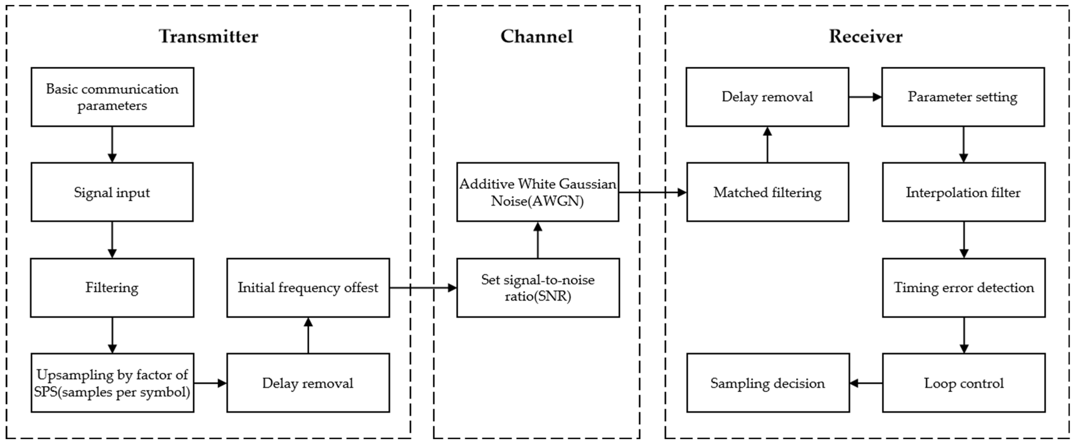
Figure 6 shows the simulation framework of the proposed time-phase synchronization error detection algorithm. This framework includes key modules such as signal generation, interpolation filtering, synchronization error detection, and sampling decision-making, used to evaluate the algorithm’s synchronization performance under different timing conditions. By comparing the constellation diagram of the transmitted signal at the source and the received signal at the receiver, the bit error rate and sampling match can be estimated, thus evaluating the feasibility of the algorithm for high-precision pseudo-code regeneration-based TFP synchronization.
In long-distance FSO communication transmission, the signal inevitably faces distance delay, initial frequency offset, and noise interference. These conditions were pre-set in the simulation. The receiver processes the preset data containing interference through interpolation filters and the timing error detection module, followed by sampling decision-making to assess the actual performance of the algorithm. The key evaluation of the algorithm’s performance is based on the comparison of the constellation diagrams of input and output data, as shown in
Figure 7. Under conditions of space delay, initial frequency offset, and noise interference, the algorithm effectively achieved constellation diagram convergence. In the QPSK constellation diagram before synchronization, the received symbols (blue) are scattered in a ring due to carrier frequency offset and phase shift; after synchronization, the symbols tightly cluster around the ideal constellation points, indicating successful recovery of the carrier phase and clock.
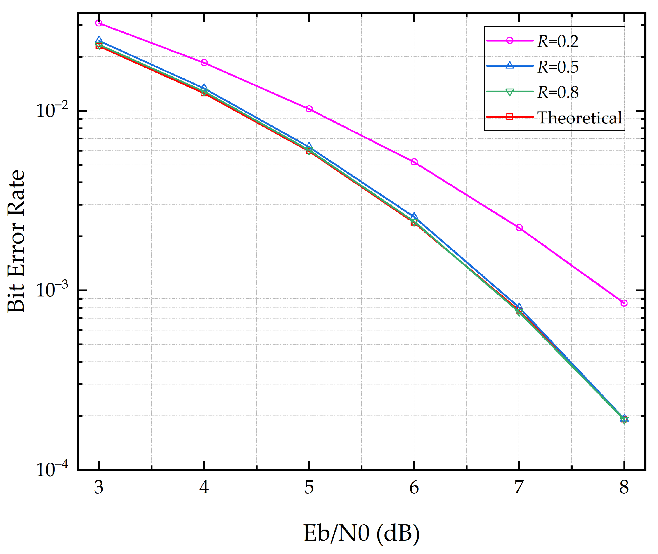
When timing errors are present, different roll-off factors
R have a significant impact on the performance of received data recovery. The larger the roll-off factor
R, the smaller the inter-symbol interference at the receiver, but the spectral efficiency decreases accordingly. As shown in
Figure 7, when
R ≥ 0.5, the system performance reaches a good level.
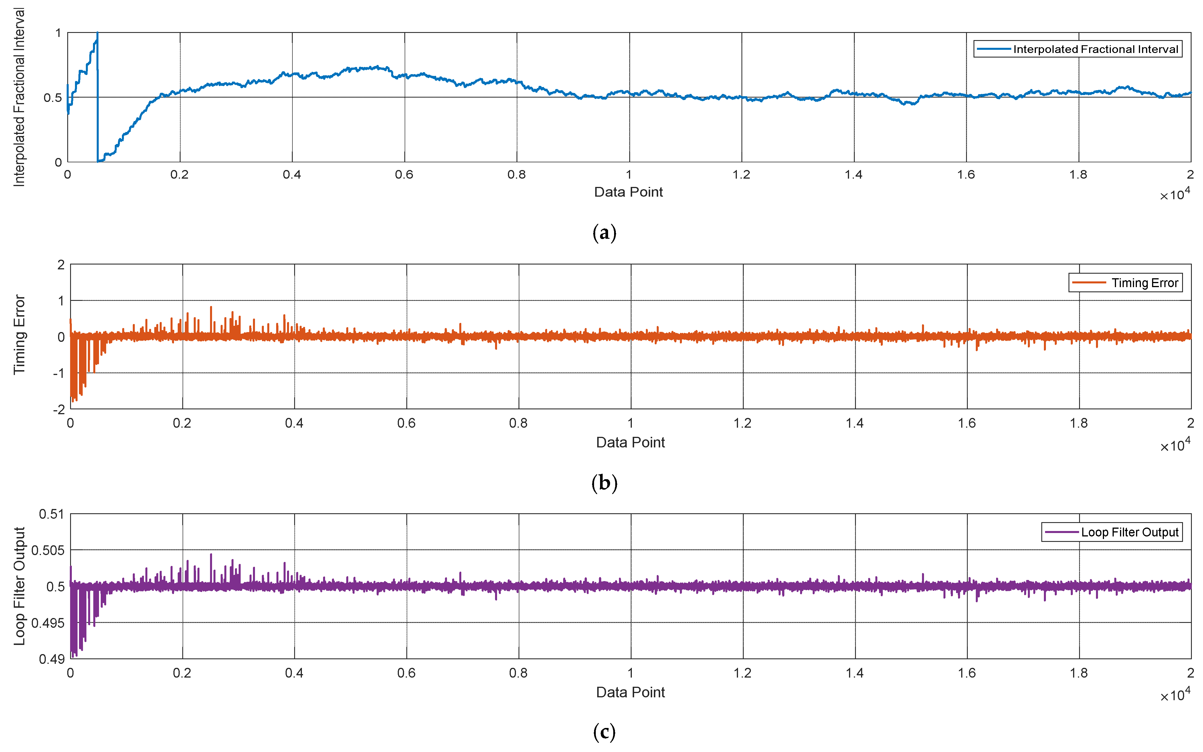
The bit synchronization loop convergence characteristics, acquisition, and tracking performance of the synchronization error detection algorithm are further analyzed. In the time-domain symbol synchronization loop, the algorithm estimates the optimal local signal sampling point through interpolation. The signal sampled by the ADC is sent into the bit synchronization loop after passing through a matched filter. Typically, timing synchronization error performance is described by the fractional interpolation interval
u; as the synchronization loop becomes stable, the fractional interpolation interval gradually converges near a constant with small fluctuations. Meanwhile, the timing error
e also tends toward zero.
Figure 8 presents the simulation results of time-domain bit synchronization tracking. The simulation results use normalized values and are represented in dimensionless units.
Based on the simulation results above, the following conclusions are drawn:
Before the synchronization loop stabilizes, the amplitude of timing error fluctuation is relatively large, and the output value of the error detector is high. After the loop stabilizes, the timing error approaches zero, with a fluctuation amplitude of approximately 0.075.
The initial value of the loop filter is set to 0.5, used to filter out noise and high-frequency components in the error signal. The loop filter output value w exhibits fluctuations before the loop stabilizes and gradually converges near the preset initial value after stabilization, with a fluctuation amplitude of approximately 0.0005.
The fractional interpolation interval u is related to the initial sampling phase and initial value. After stabilization, it converges to a constant and is used to characterize the system’s tracking performance.
From the simulation results above, it can be seen that only a small number of calculation points are needed to achieve time-phase synchronization through time-domain bit synchronization tracking, which greatly reduces the complexity of synchronization between stations. In academia, the Cramér–Rao bound (CRB) is usually used as a theoretical criterion for evaluating estimation algorithm performance. Since this algorithm includes a complete receiver verification mode, it can further evaluate its feasibility through bit error rate performance.
Figure 9 shows the bit error rate at the receiver after processing by the algorithm. Root raised cosine filtering with different roll-off factors
R and QPSK modulation is adopted, with a sampling rate of
sps = 4. The theoretical BER for QPSK under additive white Gaussian noise (AWGN) channels is as follows:
where
Eb/
N0 is the ratio of bit energy to noise power spectral density, and
Q is the Gaussian Q-function.
Figure 9 shows that when
R ≥ 0.5, the BER performance degradation caused by timing jitter is minimal and very close to the theoretical value. The impact of the roll-off factor here is consistent with the constellation simulation results previously presented.
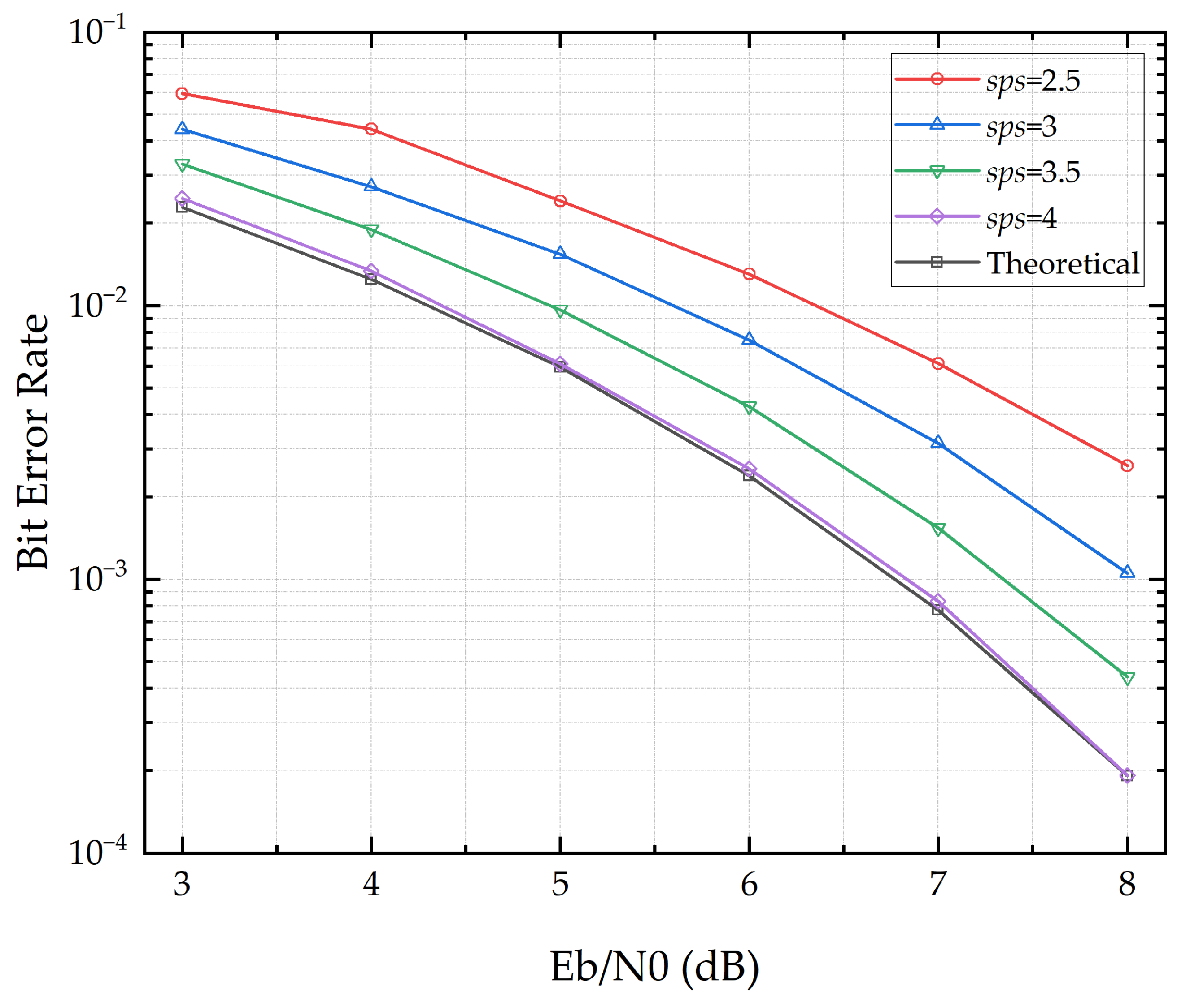
Figure 10 further analyzes the impact of sampling rate on the performance of the algorithm. The sampling rate here can be understood as the number of sampling points per symbol, which is related to the interpolation multiple. The sampling multiple has a significant impact on the BER performance of the synchronization algorithm, mainly because the algorithm’s ability to capture the best sampling point of the symbol is strongly correlated with the symbol’s sampling rate, which further affects the system’s synchronization accuracy. Let the sampling rate be
sps and the symbol period be
Ts; then the maximum synchronization resolution of the algorithm is
Ts/
sps.
To summarize, this algorithm can accurately estimate the timing error of sampling points. When sps = 4, the performance is excellent. When sps ≥ 2.5, the algorithm shows a good acquisition and tracking performance under low-SNR conditions. Considering hardware implementation complexity and resource consumption, a 2.5× sampling rate is recommended. Moreover, non-integer sampling can also avoid the threshold effect, which may impact tracking. In addition, this method is not affected by residual frequency offset, and only two sampling points are required per symbol, making it suitable for high-dynamic, low-SNR, and high-data-rate communication systems.
4. Experimental Analysis
To this end, we focus primarily on the context of distributed cooperative positioning systems for mobile platforms, in which four wide-angle laser communication electro-optical pods are employed as the FSO communication front-ends to form a one-to-two main–auxiliary station network. Such a symmetric optical link can effectively eliminate the impact of long-term thermal drift on frequency transmission. Each electro-optical pod terminal is equipped with an integrated signal and TFP processing module. This terminal module adopts a high-speed, integrated free-space TFP data transmission technology based on pseudo-code regenerative ranging, utilizing FPGA to perform pseudo-code modulation and demodulation of clock and data signals.
By combining the anti-disturbance capability of microwave systems with the high bandwidth advantage of optical systems, this approach resolves the traditional trade-off between high-speed communication and high-precision synchronization. It successfully achieves highly stable transmission and high-precision synchronization of TFP signals at a communication rate of 1.5 Gbps.
4.1. System Integration and Experimental Conditions
This section conducts outdoor experimental verification of the previously described TFP-synchronization transmission technology. Under outdoor conditions, a TFP-synchronization forwarding system between a main station and auxiliary stations is established. The system principle and device block diagrams have been detailed in
Figure 1 and
Figure 2 in
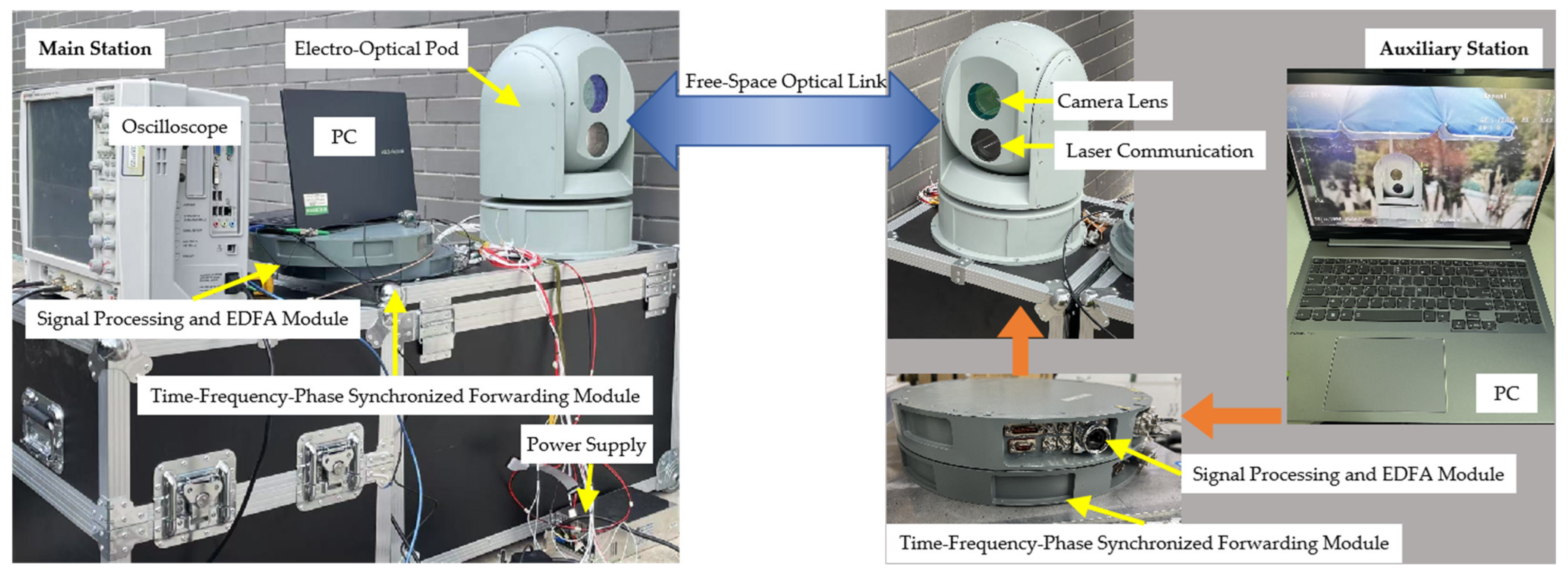
Section 2. After full system integration, the setup is as shown in
Figure 11. Both the main station and auxiliary stations are equipped with independently developed wide-angle laser communication electro-optical pods (hereinafter referred to as electro-optical pods), realizing integrated laser communication and ranging functions. The electro-optical pods are equipped with high-speed cameras and automatic three-axis gimbals. After power-on, a spiral scan is automatically executed to capture targets and enter the tracking mode. Under dynamic conditions, the three-axis gimbals continuously adjust to maintain tracking, ensuring that both pods can stably establish a link even when the platforms vibrate or move. The laser communication wavelengths at the main and auxiliary stations are 1563 nm and 1540 nm, respectively. Interference is eliminated using optical filters, followed by coaxial transceiver lens groups and detectors to convert between optical and electrical signals.
During the initialization process, the host computer monitors the communication BER. Once a BER lower than the preset threshold of 10−5 is continuously maintained within 27 s, normal data communication is enabled. At this point, the external indicator light on the vehicle-mounted terminal remains steadily illuminated to indicate successful communication link establishment. If the BER does not meet the threshold, the indicator light alternately flashes until recovery.
During the experiment, user data are converted and amplified by the TFP-synchronization forwarding module and signal processing module integrated under the electro-optical pods, and then transmitted. The receiver performs optical-to-electrical signal processing and realizes the recovery and retransmission of TFP-synchronization information.
As shown in
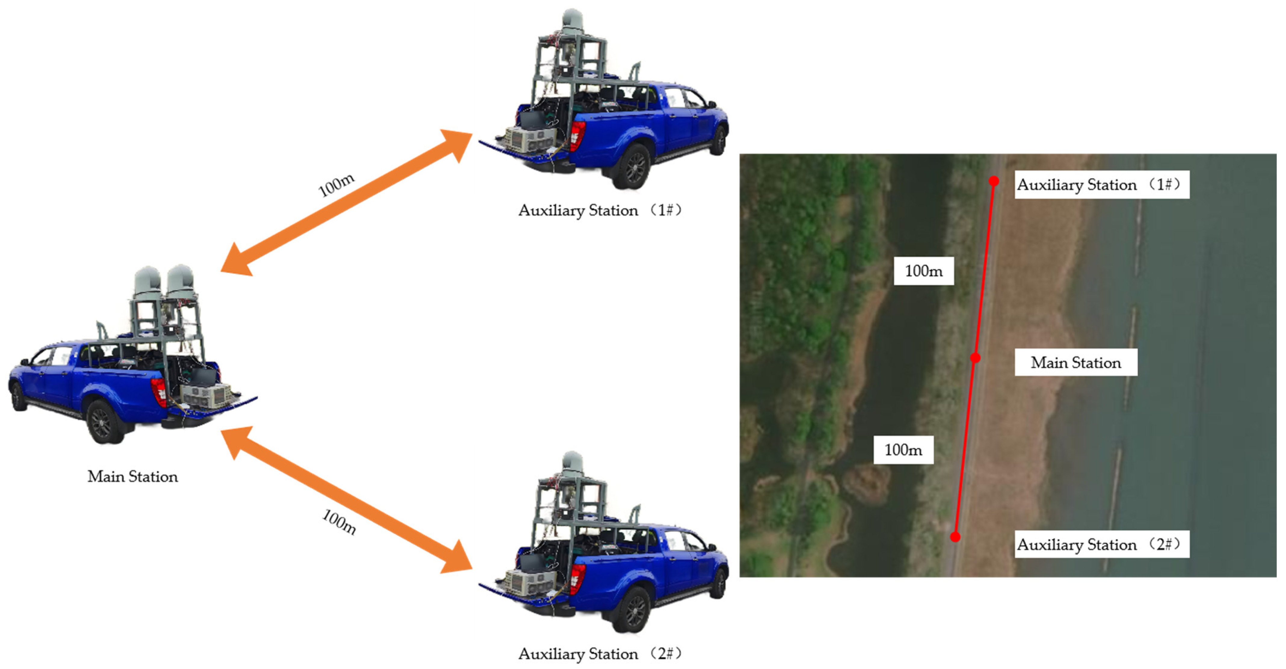
Figure 12, four integrated systems form a one-to-two communication network, mounted on three test vehicles painted dark blue. The vehicles move in the same direction at a speed not exceeding 18 km/h. At this speed, the electro-optical pod alignment accuracy is maintained within 0.1°, with motion-induced vibration and deviation controlled within 3° and a data update rate of 100 Hz. The main station is positioned at the center, with auxiliary station (1#) and auxiliary station (2#) located 100 m away from the main station, respectively.
The experiment includes measurements and analysis in six aspects: communication rate, time synchronization accuracy, clock jitter uncertainty region, frequency synchronization accuracy, frequency stability, and system phase consistency. The specific results are as follows.
4.2. Experimental Results
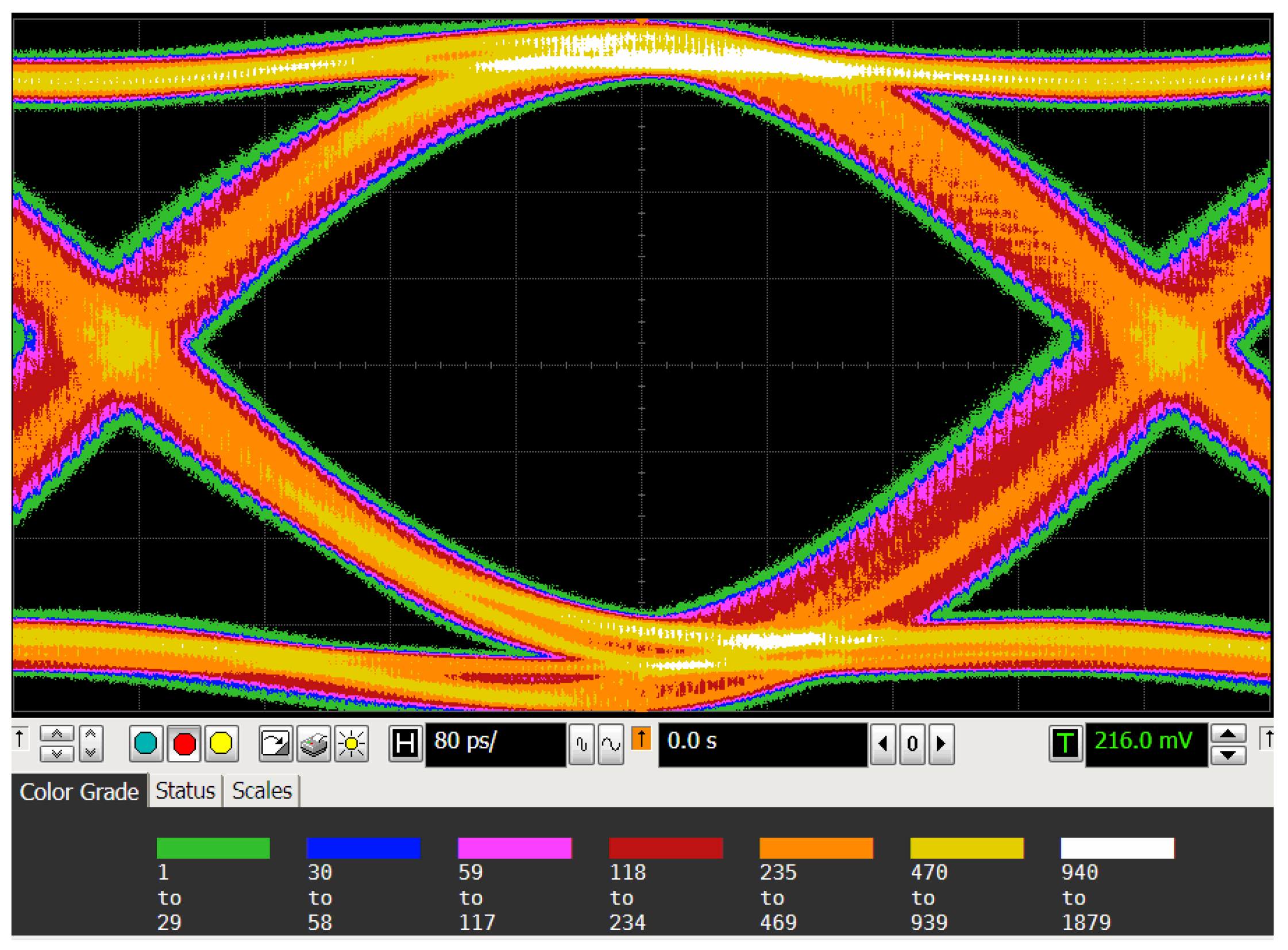
Figure 13 shows the communication eye diagram received at the user terminal of auxiliary station (1#). The relationship between the communication rate and the bit interval in the eye diagram can be calculated using the following formula:
where the bit interval
T of the eye diagram is expressed in seconds, and the communication rate
I is in bits per second (bps).
The measured eye diagram width is 660 ps (i.e., 660 × 10
−12 s), from which the communication rate is calculated as
At this rate, the system successfully achieves interconnection of the communication link while maintaining a high precision and stability in TFP synchronization.
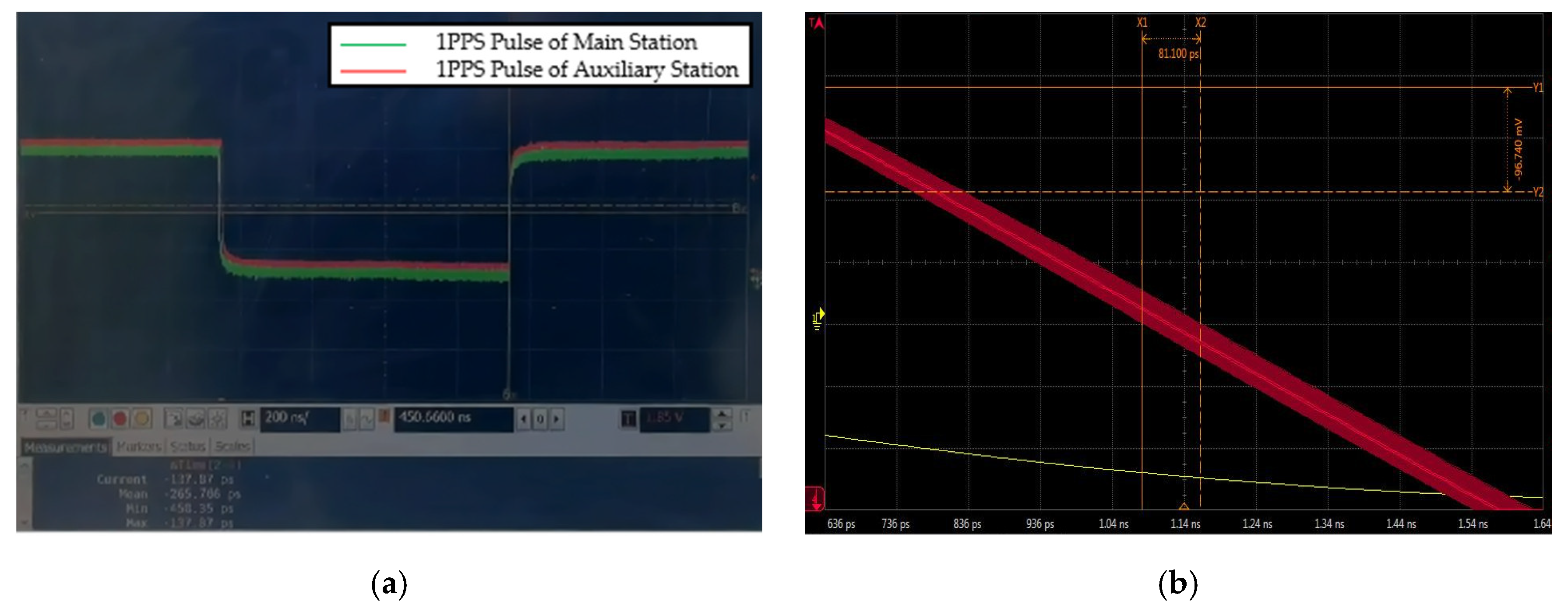
To evaluate the system’s time synchronization performance, we measured the deviation between the 1PPS pulse returned from auxiliary station (1#) and the reference 1PPS pulse of the main station. As shown in
Figure 14a, the red and green curves represent the 1PPS pulse waveforms of the main station and auxiliary station, respectively. By comparing the rising edges of the two pulse signals, the time deviation is calculated to be 265.706 ps.
Regarding clock jitter, which affects short-term time synchronization precision, we carried out optimization in both algorithm and hardware design. As shown in the test result of
Figure 14b in persistence mode, the uncertainty region is visible. Oscilloscope sampling calculation gives a measured clock jitter value of 81.1 ps.
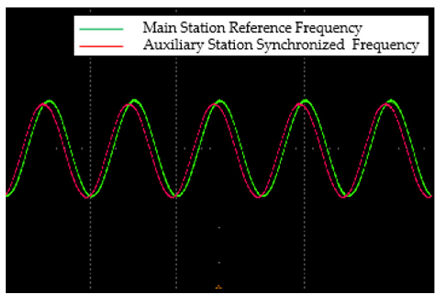
For frequency synchronization evaluation, the frequency synchronization effect between the main and auxiliary stations is acquired by the oscilloscope, as illustrated in
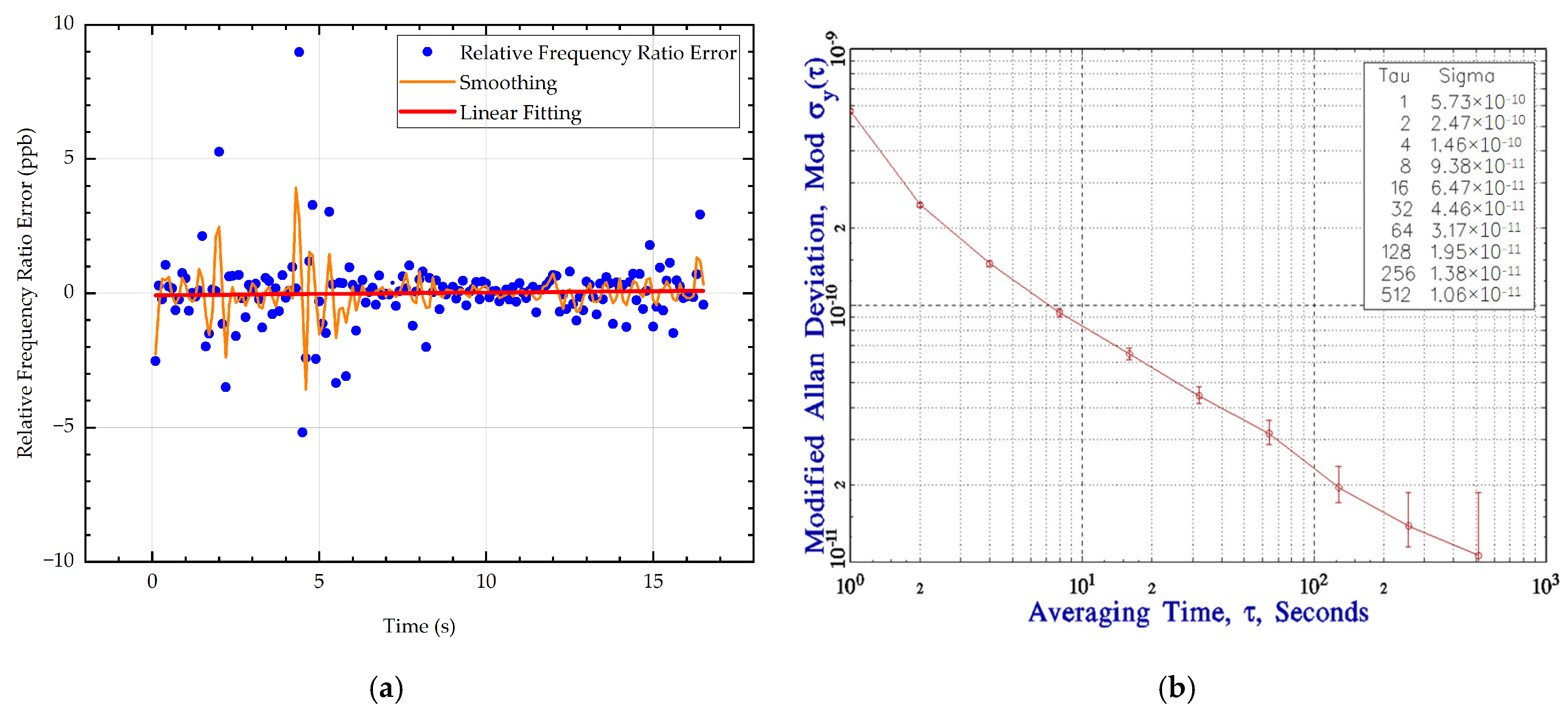
Figure 15. Frequency synchronization performance is measured by two metrics: frequency synchronization accuracy (relative frequency ratio error) and frequency stability (Allan deviation).
For high-accuracy systems, values closer to 0 indicate a smaller error between the measured and reference frequency.
Figure 16a shows the relative frequency ratio error collected by a frequency counter during the experiment. After smoothing and linear fitting, the average relative frequency ratio error obtained from the sampled data is 0.0131 ppb, indicating a near-ideal synchronization state.
Frequency stability is evaluated by Allan variance. Its expression is as follows:
where the frequency deviation
yi is measured within an observation time window
τ.
Allan deviation (ADEV) is the square root of the Allan variance and is generally expressed in dimensionless units or Hz/Hz (relative frequency deviation).
Figure 16b shows the Allan deviation curve obtained by monitoring the frequency deviation between the main and auxiliary stations using a frequency counter, with calculation performed via Stable32 (version 1.62) software. According to the curve, the frequency stability is 5.73 × 10
−10@1 s.
Phase synchronization refers to a type of synchronization in which multiple signals or clock sources maintain a consistent phase relationship, i.e., the periodic edge (usually the rising edge) of the waveform is stable and fixed in time relative to one another.
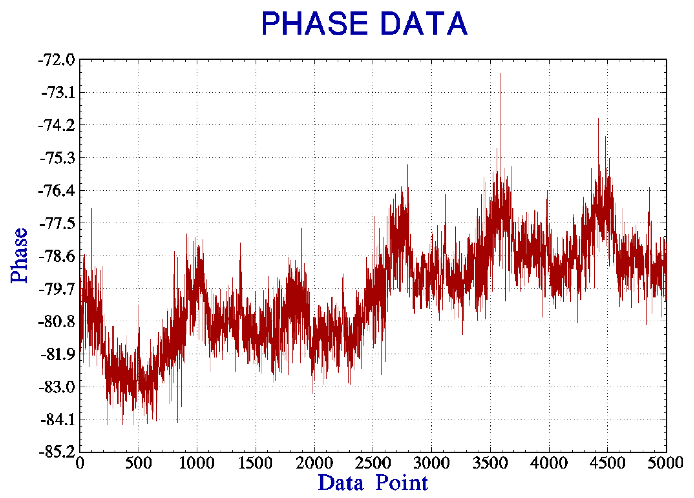
Regarding phase synchronization, once the system has stabilized, we analyzed the phase consistency over a period of time. As shown in
Figure 17, the calculated initial phase error has a mean of −79.88°, and the uncertainty in the phase error is 2.80°.
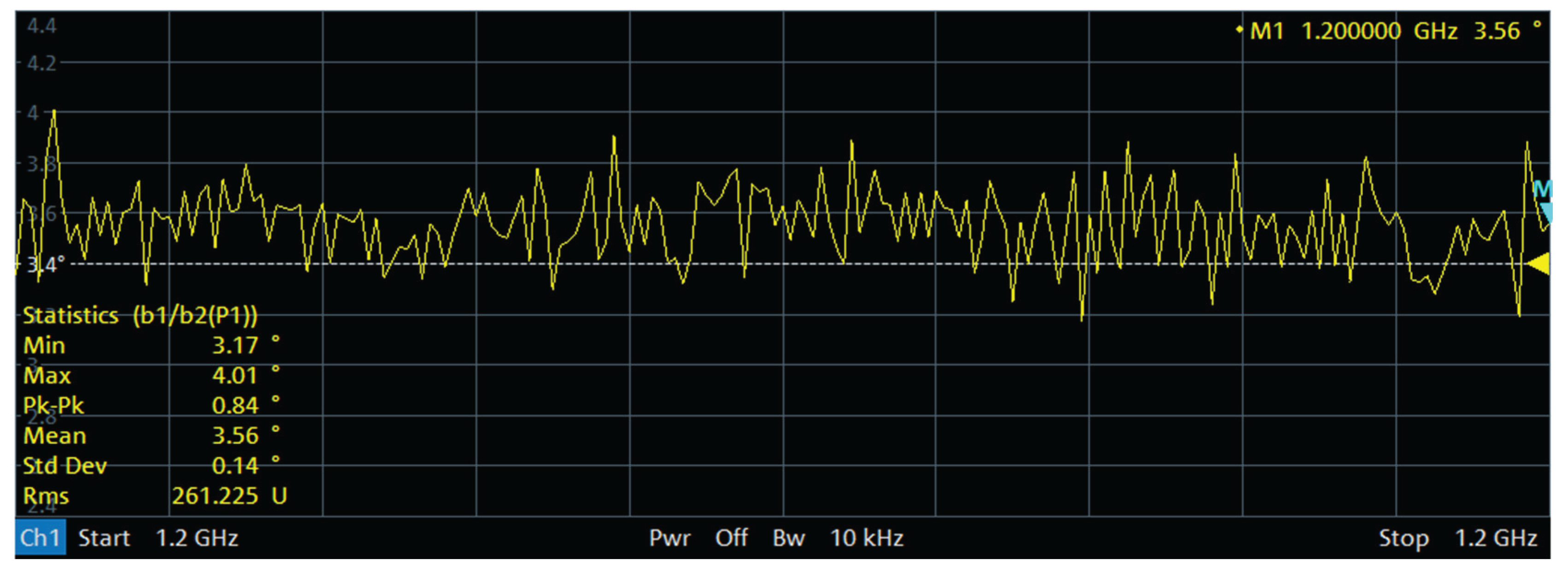
After obtaining the initial phase error, the main station uses the FPGA to eliminate the fixed initial phase error of −79.88° in real time. Then, a vector network analyzer is used to measure the phase consistency between the main and auxiliary stations, as shown in
Figure 18.
The experimental results show that although the system demonstrates high accuracy in both communication rate and time–frequency phase-synchronization performance, there is still room for further improvement in frequency synchronization stability. In the future, the pseudo-code length may be adaptively adjusted in real time based on channel conditions (e.g., Doppler shift, signal-to-noise ratio) to balance ranging accuracy and computational complexity. Furthermore, combining motion parameters of the platform (such as acceleration and angular velocity), Kalman filtering can be applied to dynamically correct phase deviation, with the aim of further enhancing the overall system performance under high-speed and dynamic conditions.
According to
Figure 18, after eliminating the fixed phase error, the system exhibits a phase uncertainty of 3.56°, which is the final phase synchronization accuracy of the system.
Although this system demonstrates innovation in FSO transmission on dynamic platforms, aspects such as laser transceiving, electro-optical pod stabilization, and TFP signal processing introduce higher power consumption and system complexity compared to conventional technologies, which can be further optimized in subsequent research. In mobile multi-node scenarios, platforms such as UAV or vehicle-mounted systems are sensitive to power supply capacity and thermal dissipation, making it necessary to improve the system towards low-power consumption, miniaturization, and integration.
To meet high-precision synchronization requirements, the system incorporates pseudo-code modulation, electro-optical stabilization, and precise alignment mechanisms, and it adopts a dual-channel link design, thereby increasing the complexity of control algorithms, hardware design, and scheduling strategies.
However, the system was originally designed for high-speed dynamic platform networking. The hardware and algorithm software at each terminal are highly consistent, making node expansion relatively straightforward. Moreover, visual and beam management mechanisms have been incorporated into the optical communication links to ensure system scalability and network deployment flexibility.
5. Conclusions
To address the limitations of traditional microwave-based synchronization accuracy and the impracticality of fiber-optic networks for mobile platforms, this paper proposes a time–frequency phase (TFP)-synchronization transmission scheme based on free-space optoelectronic hybrid technology. A symmetric laser link is constructed in a one-to-many (main-to-auxiliary) network, effectively mitigating the long-term frequency drift. Furthermore, by employing pseudo-code regeneration technology, the scheme integrates high-bandwidth data communication with high-precision time and frequency synchronization, leveraging the high-speed advantage of optical systems and the anti-disturbance robustness of microwave systems.
An outdoor dynamic platform communication system composed of one main station and two auxiliary stations, equipped with four wide-angle laser communication electro-optical pods, was established to validate the proposed scheme. The experimental results demonstrate that under a data transmission rate of 1.5 Gbps, the system achieves high-precision synchronization of time, frequency, and phase:
The time synchronization accuracy between the main and auxiliary stations reaches the picosecond level (clock jitter approximately 81.1 ps, 1PPS offset error 265.706 ps);
The frequency synchronization exhibits extremely high accuracy (average relative frequency deviation between main and auxiliary stations is 0.0131 ppb), and the frequency stability yields an Allan deviation of approximately 5.73 × 10⁻¹⁰@1 s;
The phase synchronization precision is approximately 3.56° (after eliminating the initial phase offset).
These results verify the feasibility of the proposed FSO communication synchronization architecture, which can simultaneously meet the requirements for high-speed communication and high-stability synchronization in environments lacking fiber infrastructure. Compared to conventional microwave-only schemes, the synchronization precision achieved by this system is significantly improved, fulfilling the stringent demands of mobile platform applications such as distributed collaborative positioning. The proposed approach thus offers a viable technical pathway for time–frequency phase synchronization and communication among remote mobile carriers.
