1. Introduction
Practical and efficient heat dissipation in medium- to high-power-over-fiber devices is desirable to extend their maximum power specifications, reliability, and lifetime. Optical power converter (OPC, or LPC for “Laser Power Converter”) devices are being developed for the different requirements of optical wireless power transmission (OWPT) and power-over-fiber (PoF) applications [
1,
2,
3,
4,
5,
6,
7,
8,
9,
10,
11,
12,
13,
14,
15,
16,
17,
18,
19,
20,
21,
22,
23,
24,
25,
26,
27,
28,
29,
30,
31,
32,
33]. For such OWPT and PoF applications, LPCs provide unbeatable galvanic isolation between the power source and the devices to be protected. In particular, Broadcom’s vertical multijunction LPCs continue to be implemented with the aim of endowing key optically powered probes, sensors, and electronic subsystems with increasing output power capabilities [
34,
35,
36,
37]. Such LPCs are optimally designed for various spectral, power, and temperature ranges. They have been demonstrated to be stable and reliable for different power-over-fiber or power-beaming applications. Power-demanding, remote, isolated, and backup applications are, therefore, readily satisfied with such vertical multijunction LPC products, which are distinctively capable of producing watts of output power.
The technological demand to increase LPCs’ electrical output power, run LPCs at a higher conversion efficiency, and operate LPCs in different harsh environments create a need for different and/or more efficient thermal dissipation strategies. Heat is generated in the active parts of the semiconductor chip of LPCs because the light-to-electrical conversion efficiency is never perfect, even under the best possible optimal power transfer conditions. Heat is generated by the input optical energy that is not converted into usable electrical output energy, typically 40–60% of the input energy for today’s best-performing devices. Therefore, adequate heat management is essential to ensure better optical power conversion performances and avoid overheating and related performance degradations, as well as run-away conditions that can damage the power converters themselves.
In addition to the standard approaches to heat management developed for electronic and opto-electronic components, new strategies can be beneficial for LPCs. Thermal management strategies may include some or all of the following: the use of thermal heatsinks typically made of metal, heat-conductive isolating ceramics, high-thermal-conductivity glues and epoxies, or void-free solder attach or cooling strategies based on air flow and liquid cooling circuits.
For high-power applications, the standard approaches to heat dissipation mentioned above are generally used but still have inevitable limits, so alternative methods are worth investigating. Electric utilities, for example, have, for a long time, used the immersion of entire systems like transformers in insulating oil [
38,
39]. In this approach, the heat released by components is efficiently transferred to the surrounding oil without the need for air flow or additional heatsinks. Most insulating oils are not corrosive and have good electrical insulation properties, making them compatible with large electrical components like transformers, capacitors, circuit breakers, and other high-power and high-voltage elements.
A key application of PoF systems is using them to power up and isolate sensors and signal circuits in harsh high-voltage and high-current switching environments, where, as mentioned above, insulating oil may be used for insulating and cooling capabilities. However, LPCs are typically designed to be used in air, which has relatively low dielectric breakdown properties when compared to non-electrically conducting liquids or solid media. Transformer oil has a dielectric breakdown of >30 kV/mm compared to air at ~3 kV/mm. This, along with the benefits of heat dissipation, makes it a potential candidate for use with PoF systems if the components can be shown to be compatible with an oil environment with respect to performance, safety, and reliability. In particular, we wish to find out whether the high-intensity laser light emitted from the fiber tip in a PoF system can travel unimpeded, and without affecting the oil medium, to reach the active die in the LPC.
Special optical fibers have been designed as sensors to monitor the status of transformer oils in situ [
39]. Hayber, for example, used a section of a fiber stripped of its cladding and immersed in oil, allowing the evanescent part of light to sense the index of refraction of the oil to provide feedback on its condition [
40]. In this and most cases, light remains trapped inside the fiber and does not propagate directly in an oil environment. To our knowledge, the compatibility of LPCs using high-power laser light with oil has not yet been discussed nor investigated. The proposal here is not to use an LPC as a sensor element but instead to use the isolated electrical power generated by the LPC to drive active sensors, as opposed to passive sensors. Laser devices can have very high power densities when focused via lenses or, in the case of fiber lasers, at the output of the fiber tip. Instinctively, one would refrain from running high-power laser devices in a potentially flammable liquid environment, and initial attempts to use LPCs directly in oil might therefore involve the use of hermetic sealing methods to prevent high-power laser light from interacting with oil. Here, we demonstrate that LPC devices with fiber lasers can be safely and efficiently used in transformer oil without the need to isolate laser light from the oil. We show that oil is actually compatible with the key elements of an LPC system and could be beneficial. The full immersion of LPCs and their input light source in oil could be an efficient and simple method for achieving improved heat management at reduced costs.
2. Materials and Methods
The devices used for this study were standard LPC devices based on the vertical epitaxial heterostructure architecture (VEHSA) design [
34,
41]. Both the 808 nm and 976 nm LPCs use GaAs and InGaAs absorbing layers lattice-matched to GaAs and metamorphic GaAs substrates, respectively. In both cases, the Beer–Lambert law was used to determine the thicknesses of the individual subcells, with the target of having each subcell absorbing an equivalent fraction of the incident light, for the wavelengths and temperatures of interest. The subcells have increasing thicknesses from the top subcell (thinnest) to the bottom subcell (thickest). The methodology used to apply the Beer–Lambert approach has been described previously [
34]. The epitaxial layers were grown using commercial production Aixtron Metal–Organic Chemical Vapor Deposition (MOCVD) reactors.
Wafer fabrication uses standard blanket back-metallization, front ohmic contacts, and antireflection coatings (ARCs) constructed from layers of Al2O3 and TiO2. ARCs typically reduce the reflectivity (R) of the incident beam to R < 4% for the spectral range of interest.
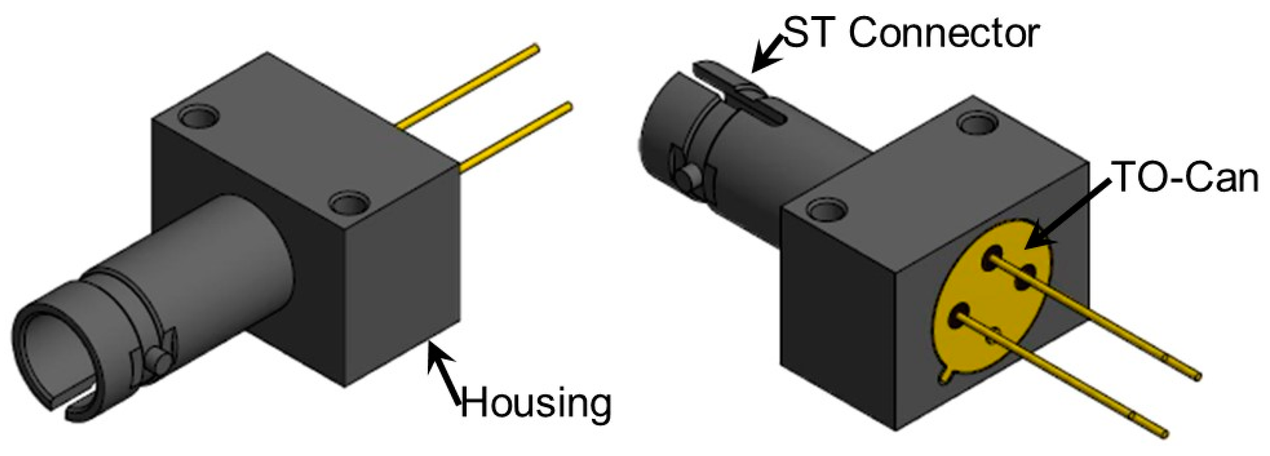
In these devices, the active dies have an area of ~0.15 cm
2 and are assembled inside a hermetic TO-can package mounted inside a brass housing with an ST optical connector for the optical fiber. The assembled device is shown in
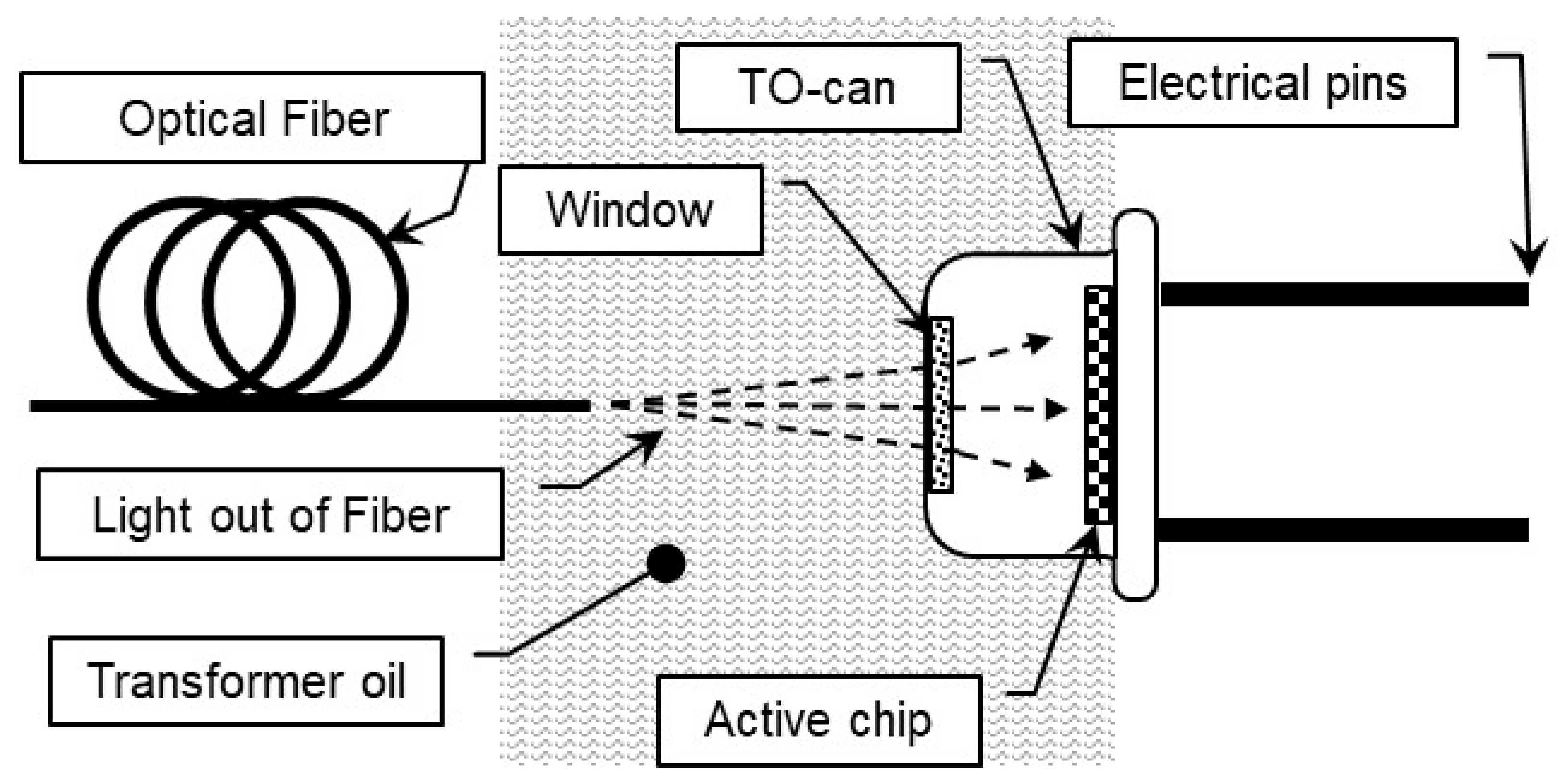
Figure 1. The TO-can itself is hermetic, but the ST connector on the housing is not. Therefore, when the device is connected to an optical fiber and immersed in a liquid, the liquid will freely flow inside and fill the volume between the fiber and the TO-can window.
Figure 2 illustrates this situation by showing the laser light emerging from the fiber tip and traveling towards the active LPC device. The TO-can window has an ARC designed for operation in air. Transformer oil has an index of refraction of n~1.45 at the wavelengths of interest here, 800–1000 nm. A rough calculation using the standard equation for reflection, R = [(n
1 − n
2)/(n
1 + n
2)]
2 where n
1 ~1.45 for oil, and n
2 ~1.3 for the ARC, shows that an increase in reflection of no more than ~1% from the TO-can glass window is expected upon immersion in oil. No efforts were made in this work to optimize the ARC between the oil and glass medium. It is worth noting that a close-to-optimum low reflection of <0.1% would be attained without the use of an ARC between the oil and glass.
The optical fibers used have a Numerical Aperture (NA) of ~0.22 in air and a core diameter between 105 microns and 400 microns, depending on the laser diode used. For a fiber laser power of 6 W and a core of 105 microns, the intensity of light as it comes out of the fiber tip is ~80 kW/cm
2 and ~100 W/cm
2 after reaching the active device. But since transformer oil is transparent in the infrared region of interest [
42], even these very high power densities are not expected to create issues. This is in fact a key point shown in the sections below.
A difference to consider is the angular spread of the beam as the light leaves the optical fiber and expands into the oil medium as opposed to air. In this case, the refractive index of oil is more closely matched to that of the fiber core, and the outgoing beam is narrower. For an NA of 0.22 in air, the effective NA in oil is NAoil~NA × (nair/noil)~0.15. This results in a slightly narrower beam width and higher peak intensity profile at the window and further down at the active die. For the multi-mode fiber used here, the intensity profile was found to roughly fit a super-Gaussian or flat top hat profile which helps to keep the peak intensity below the threshold for damage as compared to a narrower Gaussian profile.
3. Results
The device performance results have been reported in detail previously [
34,
35,
36,
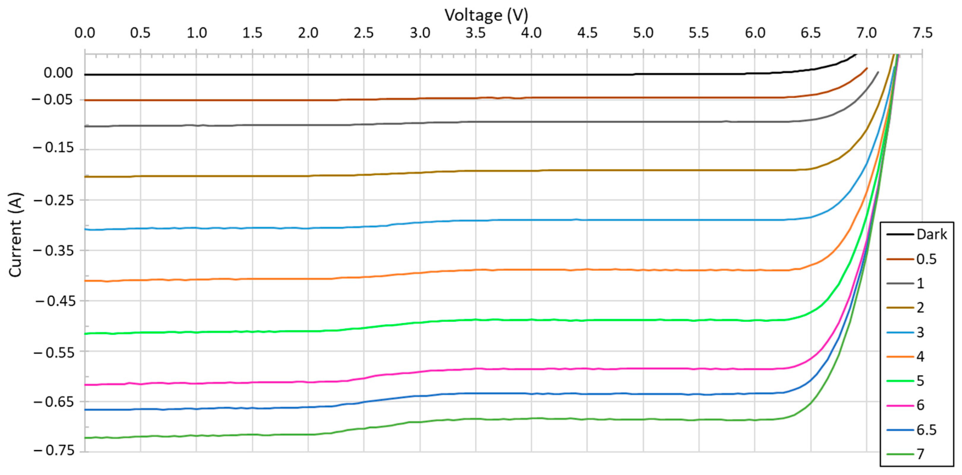
37]. Similarly, here, for performance measurements, the current–voltage (I–V) characteristics of the device in air were acquired using a Keithley 2601B source-meter in a four-wire probing mode. The results for a typical AFBR-POC306A1 device are shown in
Figure 3 at 25 °C for input powers ranging from 0 (dark current) to 7 W. The open voltage circuit (V
oc) increases slightly with input power to reach ~7.25 V at 4–7 W.
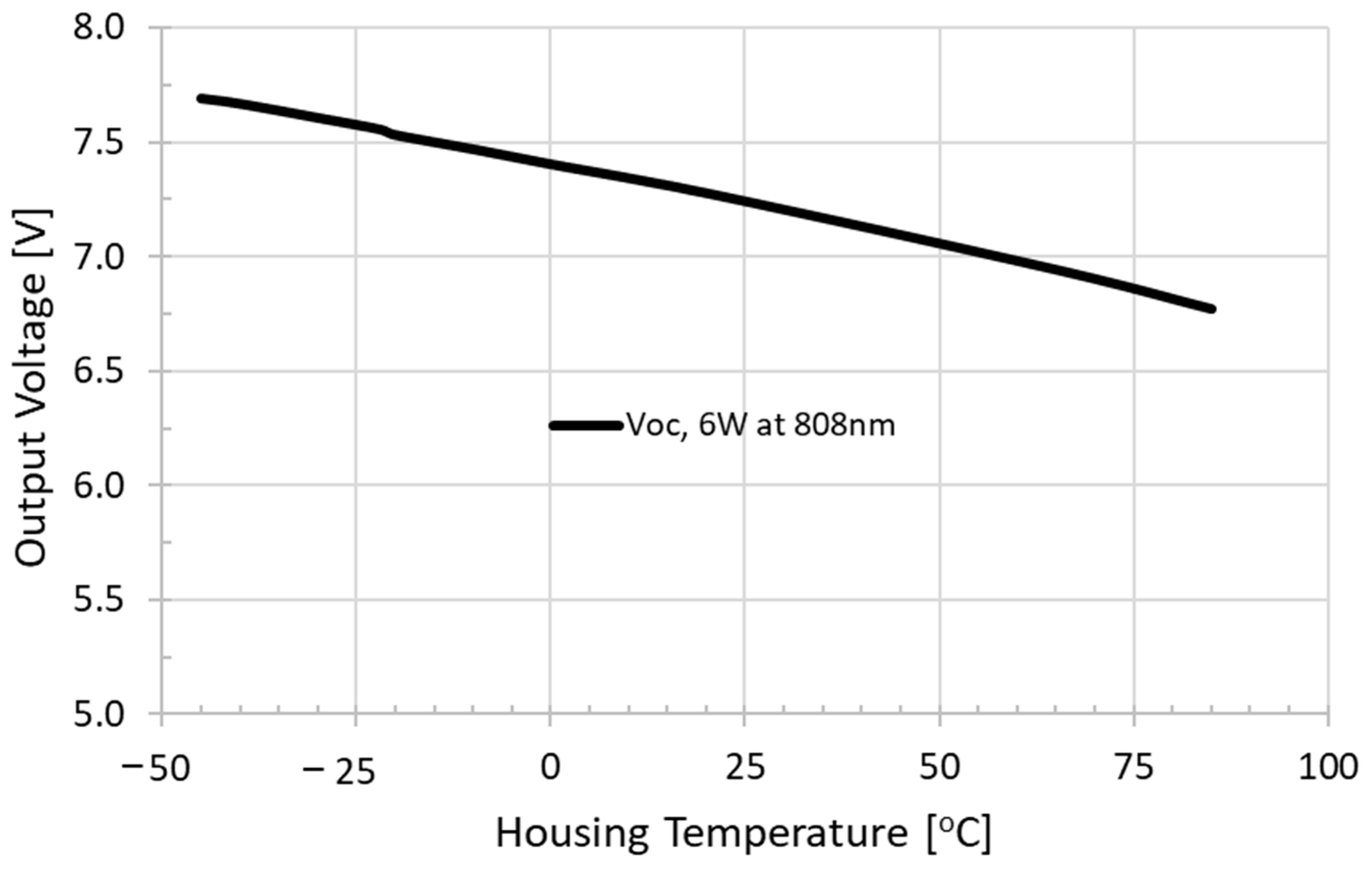
For constant input power, the V
oc parameter can be used as an indirect measure of the temperature of the active region of the device. This is shown in
Figure 4 where V
oc drops at a rate of ~6.7 mV/°C for an input power of 6 W. The data in
Figure 4 were obtained by affixing the housing of the device onto a large heatsink and placing it inside a temperature-controlled environmental chamber with continuous air circulation to keep the heatsink and the device’s housing at the desired temperature. The I–V data were acquired within a quick 1–2 s after turning on the laser to avoid additional local heating. The data in
Figure 4 thus provide a calibration between the measured V
oc and the housing temperature.
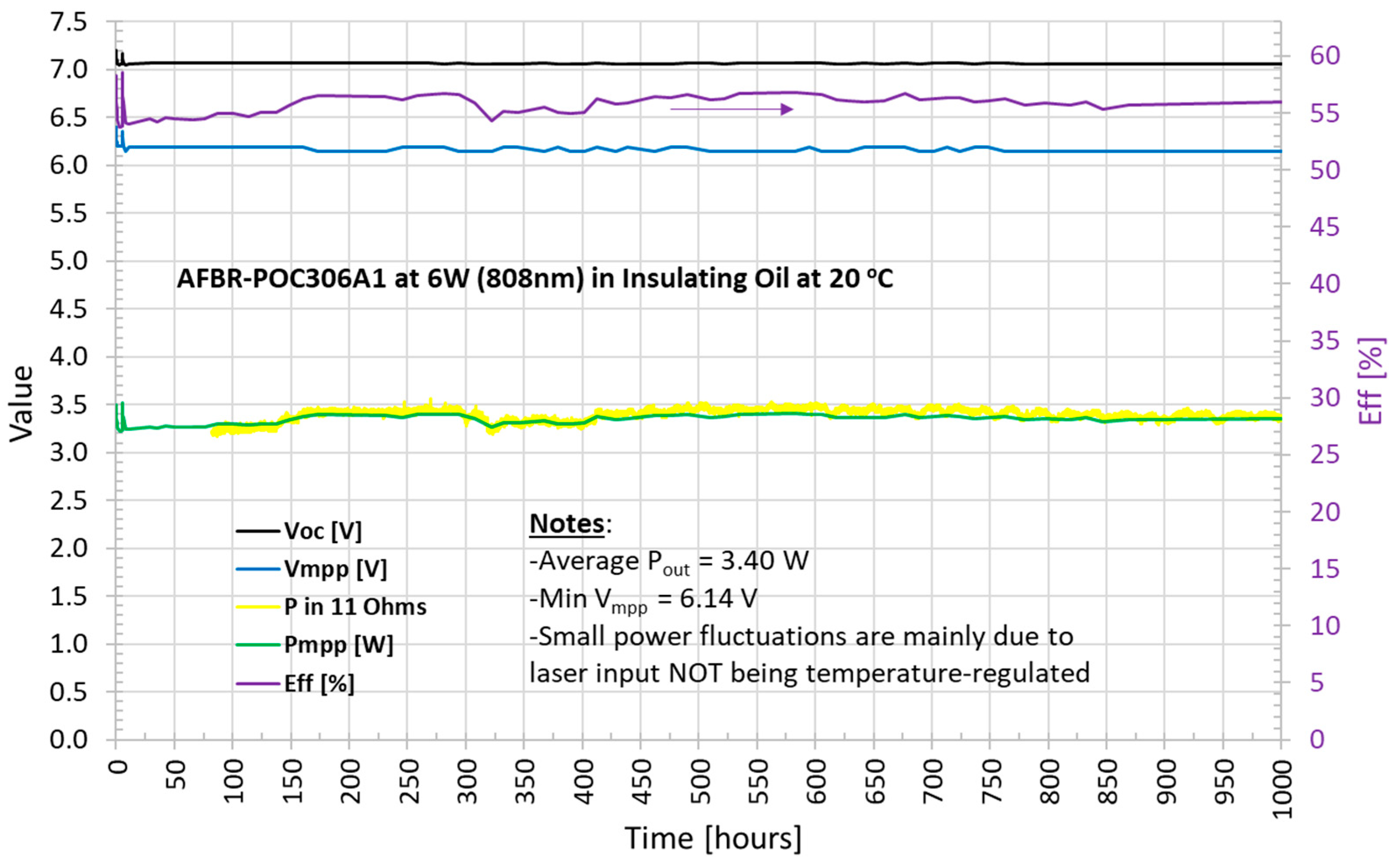
The oil immersion experiments were performed by clamping the AFBR-POC306A1 LPC to a small 42 g flat heatsink and connecting the LPC to a calibrated 808 nm fibered laser diode with an ST connector. The output pins of the LPC device were connected to an 11 Ω external resistor load, which is close to the optimal power transfer conditions for an input power of 6 W. Once connected, the device and its optical fiber were immersed in about 250 mL of commercial Voltesso 35 transformer oil [
43] inside a metal container.
A quick I–V test was performed at the onset (t = 0) to verify the I–V characteristics and obtain V
oc. The laser was then left running continuously at 6 W for the remainder of the experiment while monitoring the voltage across the 11 Ω load resistor as a function of time using a data logger from DataQ Instrument Inc. A total time of 1000 h corresponding to ~42 days of continuous operation was monitored. The external load resistor was occasionally disconnected for a short time to measure the I–V characteristics of the device to extract the key I–V parameters: V
oc, V
mpp, and Eff, where V
oc is the open circuit voltage, V
mpp is the voltage at the maximum power point, and Eff = P
mpp/P
in is the efficiency. These results are compiled in
Figure 5.
The V
oc shown in
Figure 5 remained stable at ~7.05 V throughout the test, indicating a housing temperature of ~50 °C based on the calibration from
Figure 4. A slightly higher value of ~7.2 V was measured at the very beginning, indicating that the housing temperature was slightly cooler by about 20–25 °C at the onset when the oil was still at room temperature.
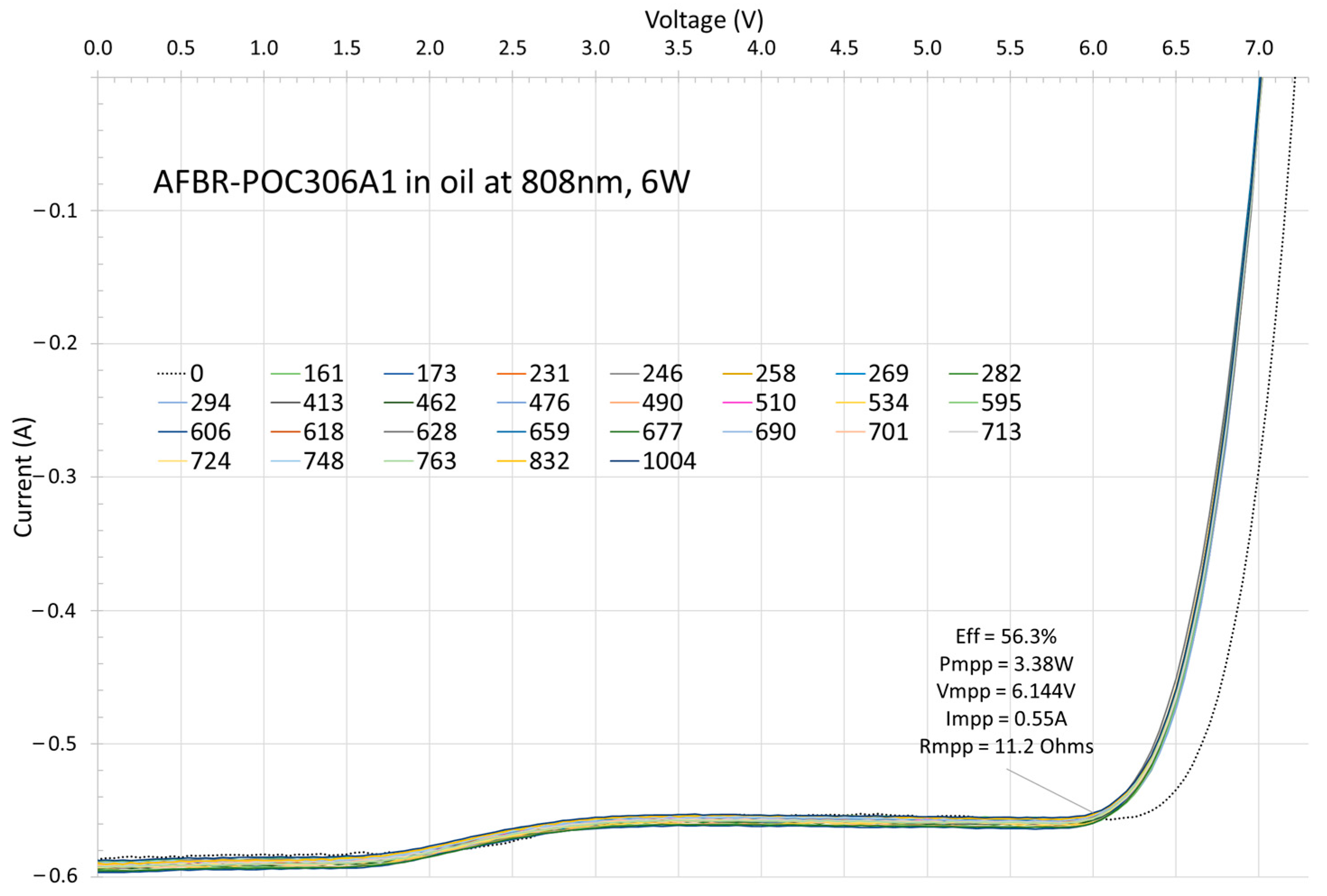
Figure 6 shows this more clearly from the series of I–V plots extracted at different times throughout the experiments, as explained above. The thin dotted line shows a V
oc of 7.2 V at the onset, as well as a higher V
mpp and efficiency. This is expected in the normal operation of the LPC as heat generated in the active die eventually establishes a gradient of temperature from the die to the surrounding oil and to the ambient temperature (~20 °C). V
mpp, P
mpp, and Eff [%], as well as the power transferred to the 11 Ω resistor, were also found to be stable throughout the 1000 h duration. The small fluctuations seen on the graph in
Figure 5 were caused mainly by room temperature fluctuations, which affect the laser output power.
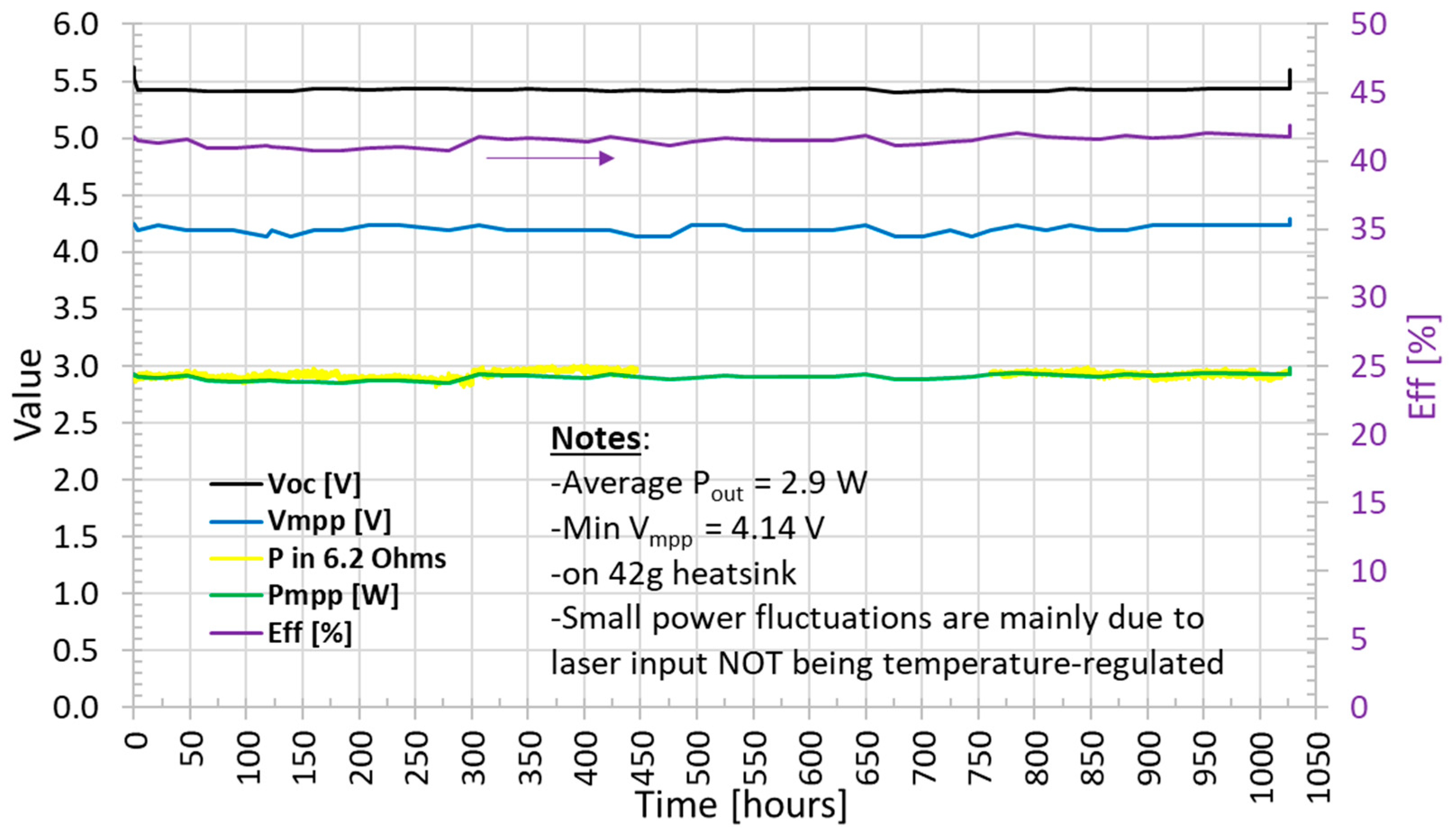
A similar test was performed using a device with the same packaging but with a different LPC die inside optimized for the 940–980 nm spectrum range (AFBR-POC306A5). The results are shown in
Figure 7 for a total test time of 1027 h (43 days). Here, the fibered laser diode power used had a wavelength of 975 nm and a power output of 7 W. The LPC was driving a 6.2 Ω load resistor to achieve near optimal power transfer conditions. A steady response in the key parameters was seen again over the course of the experiment, demonstrating the stability of the system.
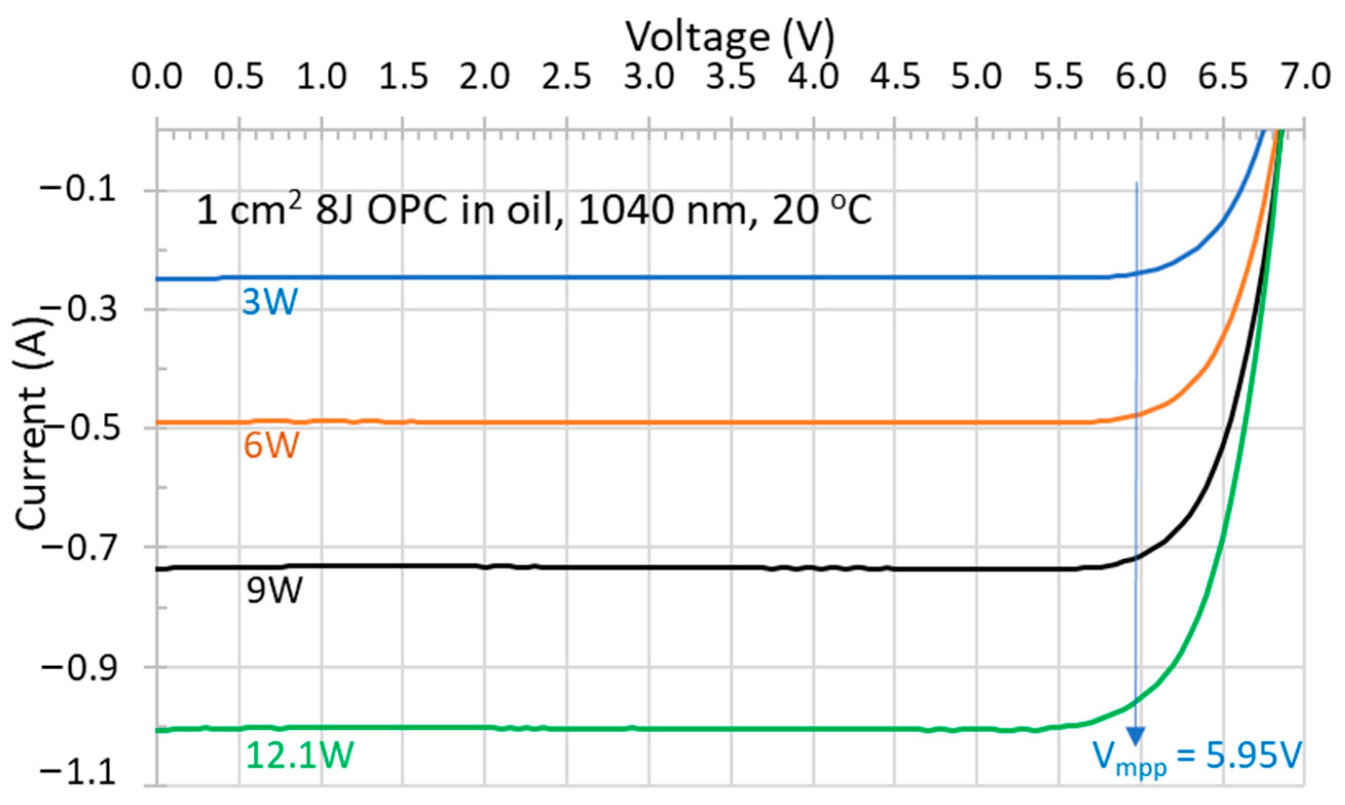
As a proof of concept for higher-power applications and improved heat extraction,
Figure 8 shows the results obtained with a 1 cm
2 bare chip mounted on an AlN carrier immersed directly in oil. Here, the LPC design is based on an 8J vertical multijunction VEHSA structure, which is currently being developed and commercialized for power-beaming applications [
44]. The multijunction structure and absorbing layers in this case were optimized for operation with a ~1040–1060 nm wavelength. More performance details will be reported in a separate future publication, but these results generically exemplify the case for high-power LPC chips at longer wavelengths. For the highest input power used here, 12 W, an output power of P
mpp = 5.7 W was obtained, while V
mpp was maintained at 5.95 V at an optimal load of 6.1 Ohms.
The results suggest that for applications requiring high output powers or for applications requiring large-area dense arrays of high-power LPC chips, packaging strategies based on oil immersion could improve heat extraction in areas away from the active area by initiating the direct physical contact of the active die with oil. This approach can facilitate the thermal management constraints of LPC systems. It should be noted that in this proof of concept, the chips’ ARC was designed for a beam incident from air. As such, oil immersion increases the reflected light and decreases the overall conversion efficiency. A conversion efficiency of Eff ~47.5% was obtained for the results shown in
Figure 8, but the ARC design could readily be adapted for the oil–die interface, thereby reducing reflections and boosting the overall conversion efficiency to 50% or greater.
4. Discussion
We demonstrated that LPC systems using infrared light from 800 nm to 980 nm with up to 7 W of output power can function properly and over extended periods of time when fully immersed in a transformer oil environment. Initial tests also showed that the operation of bare dies at ~1050 nm with up to 12 W of power is also feasible. The optical fiber, the propagation of light with very high intensity at the tip of the fiber, and the packaging material are all compatible with operation in transformer oil. There were essentially three questions to answer prior to these experiments. The first concerns the chemical stability of the components of an LPC system in transformer oil. Our results showed that no deleterious reaction or effect occurred. This is not surprising since these types of oil are widely known to be non-corrosive and have been used in high-power, high-voltage industries for cooling and insulating purposes for a long time.
The second technical issue investigated was whether or not the propagation of infrared light in the wavelength range of interest here would be compatible with oil, especially with regard to the high intensity at the tip or the exit point of a high-power fiber laser. It is well known that transformer oil can degrade over time. Optical transmission/absorption in the UV–visible spectrum is in fact used to monitor oil quality by using Color Indices (CI). A typical CI absorption spectrum will show increasing broad absorption between 350 and 500 nm with increasing degrees of oil degradation but will always tail off quickly between 500 nm and 700 nm [
42]. However, very little or no absorption can be seen at ~800 nm in these spectra even for CI of 6.5, suggesting that infrared light transmission in an LPC system should perform well even in aging oil. Our data did not indicate any significant changes in the performance of the LPC system over 1000 h and demonstrated that the high power densities of light used had no significant degradation effect on oil. We did not observe the formation of any undesirable layer contamination at the fiber tip or on the LPC window that would have prevented proper transmission.
The third point to address was whether the surrounding oil could provide sufficient and adequate cooling for an LPC in operation, where 3–5 W of heat is generated locally due to the amount of light not converted into the electrical energy transferred to the load. Based on the Voc data of the LPC in continuous operation, we found that the heat generated results in a housing temperature rise of ~20–25 °C above the ambient oil temperature. This is comparable to the local heating seen when the same LPC is operated in air and cooled using a large heatsink with air circulation and demonstrates that oil immersion can be very effective in cooling an LPC system.
Our results on the full immersion of LPC systems in oil opens new possibilities for the applications of LPC systems, especially where high power is needed and more efficient heat management techniques are required. For example, some of the key applications of power over fiber are found in the fields of high-voltage transmission lines because of the practically infinite high-voltage protection offered by the fiber transmission of an LPC system. Sensors which require electrical power in high-voltage and high-power transformers could benefit from the enhanced isolation of PoF systems and their compatibility with transformer oil without extra additional and costly protection. Simple integration with the other components of the system, followed by oil immersion, becomes an interesting possibility.
Free power beaming has gained interest in the past few years and has been the subject of recent publications [
45,
46,
47,
48]. In these applications, up to 1 kW of optical powers can be delivered by a laser beam onto an array of LPC cells and then converted into electricity. Broadcom is currently developing high-power LPC cells that are compatible with high-power lasers in the 1040–1080 nm range to address this potential market. This technology is particularly useful when the deployment of electrical wires is either too costly or, as in the case of drones, for example, simply not practical. In free power beaming, the array of LPC cells must be compact and the individual cells closely spaced to capture the laser light efficiently. This type of geometry and the high optical power involved require special considerations to properly manage the large amount of heat to be dissipated. Here again, immersion in oil could be a good approach to heat management. In this case, the full immersion of the die array in the oil would provide additional heat transfer directly from the front surface of the active die while acting as a protective shield against air and humidity. One might consider a packaged system where oil flows freely between the bare LPC dies and a protective glass plate to achieve the maximum heat extraction and minimal reflections from the high-power laser beam. In essence, a glass window and transformer oil could become key elements of the packaging technology for high-power dies.
5. Conclusions
We demonstrated the use and compatibility of LPC devices with transformer oil. LPC systems using Broadcom commercial devices AFBR-POC306A1 and AFBR-POC306A5 operating with a laser fiber light of 808 nm, 6 W and 975 nm, 7 W, respectively, retained their optical power transfer characteristics, as shown by the I–V characteristics when immersed in transformer oil. Moreover, the extended life testing of ~1000 h in continuous operation showed no signs of degradation in the optical-to-electrical power conversion nor in the I–V characteristics, thereby showing good stability and compatibility between the oil and the key components of the LPC system: fiber, laser light, and the LPC. The demonstration of the use of a bare die optimized for operation with 1040–1080 nm light, immersed in oil, was also successful.
Author Contributions
Conceptualization, S.F. and D.M; methodology, S.F. and D.M.; software, S.F. and D.M.; validation, S.F. and D.M.; formal analysis, S.F. and D.M.; investigation, S.F. and D.M.; data curation, S.F. and D.M.; writing—original draft preparation, D.M; writing—review and editing, S.F. and D.M.; visualization, S.F.; project administration, S.F. and D.M.; funding acquisition, S.F. and D.M. All authors have read and agreed to the published version of the manuscript.
Funding
This research received no external funding.
Institutional Review Board Statement
Not applicable.
Informed Consent Statement
Not applicable.
Data Availability Statement
The data that support the findings of this study are available from the corresponding author upon reasonable request.
Conflicts of Interest
The authors declare no particular conflicts of interest, but it should be noted that the authors are employed by Broadcom, a company that manufactures and sells semiconductor components, including power converter devices.
References
- Helmers, H.; Armbruster, C.; von Ravenstein, M.; Derix, D.; Schöner, C. 6-W optical power link with integrated optical data transmission. IEEE Trans. Power Electron. 2020, 35, 7904–7909. [Google Scholar] [CrossRef]
- Helmers, H.; Lopez, E.; Höhn, O.; Lackner, D.; Schön, J.; Schauerte, M.; Schachtner, M.; Dimroth, F.; Bett, A.W. 68.9% Efficient GaAs-Based Photonic Power Conversion Enabled by Photon Recycling and Optical Resonance. Phys. Status Solidi (RRL) Rapid Res. Lett. 2021, 15, 2100113. [Google Scholar] [CrossRef]
- Matsuura, M. Recent advancement in power-over-fiber technologies. Photonics 2021, 8, 335. [Google Scholar] [CrossRef]
- Martinek, P.; Prajzler, V. Power over fiber using a large core fiber and laser operating at 976 nm with 10 W power. Opt. Fiber Technol. 2023, 80, 103404. [Google Scholar] [CrossRef]
- Gou, Y.; Mou, Z.; Wang, H.; Chen, Y.; Wang, J.; Yang, H.; Deng, G. High-performance laser power converters with resistance to thermal annealing. Opt. Express 2024, 32, 8335–8342. [Google Scholar] [CrossRef]
- Jomen, R.; Tanaka, F.; Akiba, T.; Ikeda, M.; Kiryu, K.; Matsushita, M.; Maenaka, H.; Dai, P.; Lu, S.; Uchida, S. Conversion efficiencies of single-junction III-V solar cells based on InGaP, GaAs, InGaAsP, and InGaAs for laser wireless power transmission. Jpn. J. Appl. Phys. 2018, 57, 08RD12. [Google Scholar] [CrossRef]
- Komuro, Y.; Honda, S.; Kurooka, K.; Warigaya, R.; Tanaka, F.; Uchida, S. A 43.0% efficient GaInP photonic power converter with a distributed Bragg reflector under high-power 638 nm laser irradiation of 17 Wcm−2. Appl. Phys. Express 2021, 14, 052002. [Google Scholar] [CrossRef]
- Schubert, J.; Oliva, E.; Dimroth, F.; Guter, W.; Loeckenhoff, R.; Bett, A.W. High-voltage GaAs photovoltaic laser power converters. IEEE Trans. Electron. Devices 2009, 56, 170–175. [Google Scholar] [CrossRef]
- Zhao, Y.; Sun, Y.; He, Y.; Yu, S.; Dong, J. Design and fabrication of six-volt vertically-stacked GaAs photovoltaic power converter. Sci. Rep. 2016, 6, 38044. [Google Scholar] [CrossRef]
- Sun, Y.-R.; Dong, J.-R.; He, Y.; Zhao, Y.-M.; Yu, S.-Z.; Xue, J.-P.; Xue, C.; Wang, J.; Lu, Y.Q.; Ding, Y.-W. A six-junction GaAs laser power converter with different sizes of active aperture. Optoelectron. Lett. 2017, 13, 21–24. [Google Scholar] [CrossRef]
- Yin, J.; Yin, J.; Sun, Y.; Yu, S.; Zhao, Y.; Li, R.; Dong, J. 1064 nm InGaAsP multi-junction laser power converters. J. Semicond. 2020, 41, 062303. [Google Scholar] [CrossRef]
- Huang, J.; Sun, Y.; Zhao, Y.; Yu, S.; Dong, J.; Xue, J.; Xue, C.; Xue, C.; Wang, J.; Lu, Y.; et al. Four-junction AlGaAs/GaAs laser power converter. J. Semicond. 2018, 39, 044003. [Google Scholar] [CrossRef]
- Oliva, E.; Dimroth, F.; Bett, A.W. GaAs converters for high power densities of laser illumination. Prog. Photovolt. Res. Appl. 2008, 16, 289–295. [Google Scholar] [CrossRef]
- Mukherjee, J.; Jarvis, S.; Perren, M.; Sweeney, S.J. Efficiency limits of laser power converters for optical power transfer applications. J. Phys. D Appl. Phys. 2013, 46, 264006. [Google Scholar] [CrossRef]
- Khvostikov, V.P.; Kalyuzhnyy, N.A.; Mintairov, S.A.; Sorokina, S.V.; Potapovich, N.S.; Emelyanov, V.M.; Timoshina, N.K.; Andreev, V.M. Photovoltaic laser-power converter based on AlGaAs/GaAs heterostructures. Semiconductors 2016, 50, 1220–1224. [Google Scholar] [CrossRef]
- Krut, U.D.; Sudharsanan, R.; Isshiki, T.; King, R.; Karam, N.H. A 53% high efficiency GaAs vertically integrated multi-junction laser power converter. In Proceedings of the 65th DRC Device Research Conference, South Bend, IN, USA, 18–20 June 2007; pp. 123–124. [Google Scholar]
- Andreev, V.; Khvostikov, V.; Kalinovsky, V.; Lantratov, V.; Grilikhes, V.; Rumyantsev, V.; Shvarts, M.; Fokanov, V.; Pavlov, A. High current density GaAs and GaSb photovoltaic cells for laser power beaming. In Proceedings of the 3rd World Conference on Photovoltaic Energy Conversion, Osaka, Japan, 11–18 May 2003; Volume 1, pp. 761–764. [Google Scholar]
- Peña, R.; Algora, C.; Anton, I. GaAs multiple photovoltaic converters with an efficiency of 45% for monochromatic illumination. In Proceedings of the 3rd World Conference on Photovoltaic Energy Conversion, Osaka, Japan, 11–18 May 2003; pp. 228–231. [Google Scholar]
- Kalyuzhnyy, N.A.; Emelyanov, V.M.; Mintairov, S.A.; Shvarts, M.Z. InGaAs metamorphic laser (λ = 1064 nm) power converters with over 44% efficiency. AIP Conf. Proc. 2018, 2012, 110002. [Google Scholar]
- Kim, Y.; Shin, H.-B.; Lee, W.-H.; Jung, S.H.; Kim, C.Z.; Kim, H.; Lee, Y.T.; Kang, H.K. 1080 nm InGaAs laser power converters grown by MOCVD using InAlGaAs metamorphic buffer layers. Sol. Energy Mater. Sol. Cells 2019, 200, 109984. [Google Scholar] [CrossRef]
- Panchak, A.N.; Pokrovskiy, P.V.; Malevskiy, D.A.; Larionov, V.R.; Shvarts, M.Z. High-Efficiency Conversion of High-Power-Density Laser Radiation. Tech. Phys. Lett. 2019, 45, 24–26. [Google Scholar] [CrossRef]
- Fahrenbruch, A.L.; Lopez-Otero, A.; Werthen, J.G.; Wu, T.C. GaAs- and InAlGaAs-based concentrator-type cells for conversion of power transmitted by optical fibers. In Proceedings of the Conference Record of the IEEE Photovoltaic Specialists Conference, Washington, DC, USA, 13–17 May 1996; pp. 117–120. [Google Scholar]
- Fave, A.; Kaminski, A.; Gavand, M.; Mayet, L.; Laugier, A. GaAs converter for high power laser diode. In Proceedings of the Conference Record of the IEEE Photovoltaic Specialists Conference, Washington, DC, USA, 13–17 May 1996; pp. 101–104. [Google Scholar]
- Green, M.A.; Zhao, J.; Wang, A.; Wenham, S.R. 45% Efficient Silicon Photovoltaic Cell Under Monochromatic Light. IEEE Electron. Device Lett. 1992, 13, 317–318. [Google Scholar] [CrossRef]
- Höhn, O.; Walker, A.W.; Bett, A.W.; Helmers, H. Optimal laser wavelength for efficient laser power converter operation over temperature. Appl. Phys. Lett. 2016, 108, 241104. [Google Scholar] [CrossRef]
- Shan, T.; Qi, X. Design and optimization of GaAs photovoltaic converter for laser power beaming. Infrared Phys. Technol. 2015, 71, 144–150. [Google Scholar] [CrossRef]
- Khvostikov, V.P.; Sorokina, S.V.; Potapovich, N.S.; Khvostikova, O.A.; Timoshina, N.K.; Shvarts, M.Z. Modification of Photovoltaic Laser-Power (λ = 808 nm) Converters Grown by LPE. Semiconductors 2018, 52, 366–370. [Google Scholar] [CrossRef]
- Khvostikov, V.P.; Sorokina, S.V.; Potapovich, N.S.; Khvostikova, O.A.; Timoshina, N.K. Laser (λ = 809 nm) power converter based on GaAs. Semiconductors 2017, 51, 645–648. [Google Scholar] [CrossRef]
- Helmers, H.; Franke, A.; Lackner, D.; Höhn, O.; Predan, F.; Dimroth, F. 51% Efficient Photonic Power Converters for O-Band Wavelengths around 1310 nm. In Proceedings of the Conference Record of the IEEE Photovoltaic Specialists Conference, Calgary, AB, Canada, 15 June–21 August 2020; pp. 2471–2474. [Google Scholar]
- Zhao, Y.; Liang, P.; Ren, H.; Han, P. Enhanced efficiency in 808 nm GaAs laser power converters via gradient doping. AIP Adv. 2019, 9, 105206. [Google Scholar] [CrossRef]
- Beattie, M.N.; Valdivia, C.E.; Wilkins, M.M.; Zamiri, M.; Kaller, K.L.C.; Tam, M.C.; Kim, H.S.; Krich, J.J.; Wasilewski, Z.R.; Hinzer, K. High current density tunnel diodes for multi-junction photovoltaic devices on InP substrates. Appl. Phys. Lett. 2021, 118, 062101. [Google Scholar] [CrossRef]
- Wagner, L.; Reichmuth, S.K.; Philipps, S.P.; Oliva, E.; Bett, A.W.; Helmers, H. Integrated series/parallel connection for photo-voltaic laser power converters with optimized current matching. Prog. Photovolt. Res. Appl. 2020, 29, 172. [Google Scholar] [CrossRef]
- Matsuura, M.; Nomoto, H.; Mamiya, H.; Higuchi, T.; Masson, D.; Fafard, S. Over 40-W Electric Power and Optical Data Transmission Using an Optical Fiber. IEEE Trans. Power Electron. 2020, 36, 4532. [Google Scholar] [CrossRef]
- Fafard, S.; Masson, D.P. Perspective on photovoltaic optical power converters. J. Appl. Phys. 2021, 130, 160901. [Google Scholar] [CrossRef]
- Fafard, S.; Masson, D.P. High-Efficiency and High-Power Multijunction InGaAs/InP Photovoltaic Laser Power Converters for 1470 nm. Photonics 2022, 9, 438. [Google Scholar] [CrossRef]
- Fafard, S.; Masson, D.P. 74.7% Efficient GaAs-Based Laser Power Converters at 808 nm at 150 K. Photonics 2022, 9, 579. [Google Scholar] [CrossRef]
- Fafard, S.; Masson, D. 67.5% Efficient InP-Based Laser Power Converters at 1470 nm at 77 K. Photonics 2024, 11, 130. [Google Scholar] [CrossRef]
- Reddy, B.K. Latest Trends In Use Of Transformer Oils. Int. J. Eng. Trends Technol. 2019, 67, 37–39. [Google Scholar] [CrossRef]
- Karthik, M.; Nuvvula, R.S.S.; Dhanamjayulu, C.; Khan, B. Appropriate analysis on properties of various compositions on fuids with and without additives for liquid insulation in power system transformer applications. Sci. Rep. 2024, 14, 17814. [Google Scholar] [CrossRef]
- Hayber, S.E.; Tabaru, T.E.; Gucyetmez, M. Evanescent Field Absorption-Based Fiber Optic Sensor for Detecting Power Transformer Oil Degradation. Fiber Integr. Opt. 2021, 40, 229–248. [Google Scholar] [CrossRef]
- Fafard, S.; York, M.C.A.; Proulx, F.; Valdivia, C.E.; Wilkins, M.M.; Arès, R.; Aimez, V.; Hinzer, K.; Masson, D.P. Ultrahighefficiencies in vertical epitaxial heterostructure architectures. Appl. Phys. Lett. 2016, 108, 071101. [Google Scholar] [CrossRef]
- Leong, Y.S.; Ker, P.J.; Jamaludin, M.Z.; Nomanbhay, S.M.; Ismail, A.; Abdullah, F.; Looe, H.M.; Lo, C.K. UV-Vis Spectroscopy: A New Approach for Assessing the Color Index of Transformer Insulating Oil. Sensors 2018, 18, 2175. [Google Scholar] [CrossRef]
- Available online: https://www.mobil.ca/en-ca/lubricants/industrial/lubricants/product-series/product-series/voltesso (accessed on 16 April 2025).
- Fafard, S.; Masson, D. 55% Efficient High-Power Multijunction Photovoltaic Laser Power Converters for 1070 nm. Photonics 2025, 12, 406. [Google Scholar] [CrossRef]
- Nugent, T.J. Remote Electric Power Delivery via High Power Laser. In Proceedings of the Applied Industrial Optics 2019, Washington, DC, USA, 8–10 July 2019; paper T3A.4. OSA Technical Digest (Optica Publishing Group): Washington, DC, USA, 2019. [Google Scholar]
- Jaffe, P.; Nugent, T.; Strassner, B., II; Szazynski, M. Power Beaming: History, Theory, and Practice; World Scientific Series on Emerging Technologies; World Scientific Publishing Company: Singapore, 2024; Volume 5, 420p. [Google Scholar]
- Miyamoto, T. Optical WPT. In Theory and Technology of Wireless Power Transfer; CRC Press: Boca Raton, FL, USA, 2024; pp. 179–245. [Google Scholar]
- Zheng, Y.; Zhang, G.; Huan, Z.; Zhang, Y.; Yuan, G.; Li, Q.; Ding, G.; Lv, Z.; Ni, W.; Shao, Y.; et al. Wireless laser power transmission: Recent progress and future challenges. Space Sol. Power Wirel. Transm. 2024, 1, 17–26. [Google Scholar] [CrossRef]
| Disclaimer/Publisher’s Note: The statements, opinions and data contained in all publications are solely those of the individual author(s) and contributor(s) and not of MDPI and/or the editor(s). MDPI and/or the editor(s) disclaim responsibility for any injury to people or property resulting from any ideas, methods, instructions or products referred to in the content. |
© 2025 by the authors. Licensee MDPI, Basel, Switzerland. This article is an open access article distributed under the terms and conditions of the Creative Commons Attribution (CC BY) license (https://creativecommons.org/licenses/by/4.0/).
