1. Introduction
Vortex light [
1] is a special type of optical field with a transverse distribution. It has properties of phase singularity [
2], spin angular momentum [
3], and orbital angular momentum [
4]. As a result, it shows great application potential in optical fields. Specifically, these fields include optical manipulation [
5], quantum computation [
6], MEMS microfabrication [
7], and optical communication [
8]. Each photon in the optical vortex field carries lħ orbital angular momentum. As the carrier of orbital angular momentum, vortex light can transfer energy to the focused molecules or atoms, making them rotate. Consequently, the control of microscopic particles is realized [
9]. Meanwhile, with the rapid development of wireless optical communication, traditional modulation and multiplexing technologies cannot meet the future requirements of high-capacity and high-speed communication. However, the orbital angular momentum carried by vortex light theoretically exhibits infinite multiplicity in its eigenstates, with any two distinct eigenstates being mutually orthogonal. It is of great importance for optical communication technology, which has the potential to overcome communication limitations [
10].
Studies have indicated that single-phase-singularity vortex beams exhibit inherent limitations in anti-interference capability and quantum processing. Consequently, the study of single-mode vortex beams is gradually being extended to encompass the study of multimodal vortex beams generated by superposition or interference. Currently, the predominant method for superimposing vortex beams is extra-cavity superimposition with SLM modulation, which has a complex optical path structure and primarily focuses on studying the 1 μm band or the visible band [
11]. In 2014, Jaime A. Anguita et al. [
12] conducted an experimental demonstration of generating coherent superposition vortex light. It was achieved by creating a raster with superposition light fields and importing the raster phase into an SLM. In 2015, Sujuan Huang et al. [
13] generated a novel composite vortex beam. It was achieved by coaxially superposing Laguerre–Gaussian (LG) beams employing a computer-controlled SLM. In 2020, Pascuala García-Martínez et al. [
14] used two phase-modulated liquid crystal panels to superpose vortex modes. As a direct result, different vector patterns were successfully generated. In 2021, Xia Jin et al. [
15] loaded a customized hologram onto an SLM to generate an LG beam. The LG beam passed through a single-polarization vector optical generator (VOG) to generate a vector vortex beam with a corresponding topological charge. Finally, the two beams interfered to obtain a petal-shaped beam. The 2 μm band SLM is difficult to fabricate, and the device has a low damage threshold. The aforementioned method does not apply to the superposition in the 2 μm band. The 2 μm band is in the atmospheric window of high transmittance, which is conducive to the practical promotion of space optical communication. Compared with the traditional 1.5 μm communication band, the 2 μm band exhibits unique advantages. It reduces information congestion in the frequency domain. Moreover, it significantly expands the spectral bandwidth [
16]. At the same time, with the arrival of the 6G era, channel multiplexing technology has become the focus of research. Single wavelength division multiplexing technology has limitations in improving the transmission capacity. Combining wavelength division multiplexing technology and space division multiplexing technology as a solution to achieve large-capacity transmission has attracted much attention in recent years [
17]. Vortex light has unique advantages in improving system capacity and communication transmission [
18]. It is of great significance for the development of future communication technology to realize the generation and evolution of complex vortex light superposition states based on the research of 2 μm band laser technology.
In this paper, the evolution of the beam from the double HG beam superposition state to the double LG beam superposition state is realized by the astigmatism mode converter. Firstly, the double HG mode superposition state is realized in the same resonant cavity through the double-end off-axis pumping structure. Based on this, the astigmatism mode converter is added to the back end of the output mirror of the resonant cavity to convert the double HG beam superposition state into the double LG beam superposition state. The process of double mode superposition state evolution using an astigmatic mode converter is theoretically analyzed. Based on the theoretical analysis process, a double-vortex mode superposition evolution resonant cavity based on an astigmatic mode converter is designed. Finally, the light field change of double-vortex mode superposition state evolution is demonstrated experimentally.
2. Mode Superposition Evolution Theory
It has been extensively demonstrated that off-axis pumped crystals can suppress the fundamental mode, producing a Hermite–Gaussian (HG) beam. The optical field equation for HG mode can be expressed [
19]:
where
n and
m denote the number of nodes of the spot in the
x and
y directions, respectively;
is the normalization factor;
is the beam waist radius;
Hm(
x) and
Hn(
x) are Hermite polynomials;
R(
z) is the beam radius of curvature; and
is the Gouy phase.
The double HG mode superposition state is generated by double-ended off-axis pumping. The expression for the optical field is given as follows:
where
is the ratio of the optical field intensity of the two HG modes and
is the phase difference between the two modes. Thus,
Figure 1 shows the simulation diagram of the superposition of two HG modes in the same direction (
). And
Figure 2 shows the simulation diagram of the orthogonal superposition of two HG modes with a phase difference of π/2 in different directions (
).
The Laguerre–Gaussian (LG) mode is the solution of the paraxial wave equation in the cylindrical coordinate system. It has the optical field expression [
20]:
where
is the normalization factor;
p and
l are radial index and topological charge, respectively;
is the azimuthal angle;
r is the radial component of the cylindrical coordinate;
κ is the wave number;
is the Gouy phase shift; and
is the generalized Laguerre polynomial.
The double LG mode superposition state expression is given by
In order to establish a correspondence between HG modes and LG modes, define
N =
m +
n. In the optical field expression of LG modes, parameters
p and
l can be determined by
m and
n. Specifically,
p =
min(m,n) and
l =
n −
m. With these definitions, Equation (3) can be rewritten as
HG modes form an orthogonal complete system, so that LG modes can be represented by a set of HG modes:
The diagonal HG mode has a main axis at a 45° angle to the
X and
Y axes. It can be represented using HG mode expansions:
According to the optical field Equation (2), we can obtain the light field equations of two types of states. One is the superposition state of two diagonal HG modes in the same direction. The other is the superposition state of two orthogonal diagonal HG modes with a phase difference of π/2.
From Equation (6), by replacing
LGnm with the corresponding
LGpl, the expression for the LG mode when the radial index is 0, and the topological charges are −
m and
n, respectively, is obtained:
According to double LG mode superposition state optical field Equation (4), when two LG beams with opposite sign of mode order
n and −
m and phase difference of π/2 are superimposed, the superposition state light field expression is
When two LG beams with the same sign of mode order
n1 and
n2 are superimposed, the superposition state light field expression is
It can be observed that the double LG mode superposition state and the double diagonal HG mode superposition state can be represented by the same set of HG mode superposition states. However, adjacent modes that make up the superposition state of the double LG mode contain a factor . The factor corresponds to a π/2 phase difference. Thus, the double diagonal HG mode superposition state can be converted to the double LG mode superposition state by complementing the phase difference of π/2.
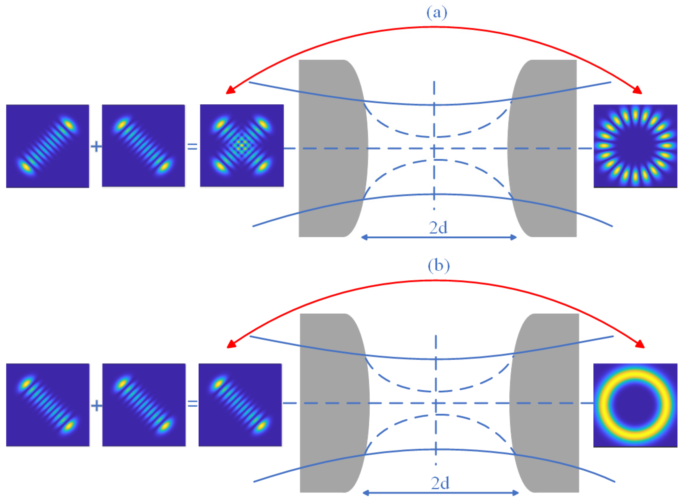
The two modes can be converted using an astigmatic mode converter to introduce a Gouy phase shift. A schematic diagram is provided in
Figure 3 for illustrative purposes. Because of refractive index differences in lens components, the astigmatic system refracts the beam. As a result, the original object point becomes two mutually perpendicular but separated short lines after imaging.
For a Gaussian beam with a non-astigmatic mode, the Gouy phase is given by Equations (1) and (3):
At the beam waist, the
expression is
For a Gaussian beam within the astigmatic region, the beam’s amplitude can be considered from two distinct cross-sectional perspectives: the
x-
z and
y-
z planes. Accordingly, the Gouy phase can be divided into two parts:
where
and
denote the beam waist positions;
and
denote the beam Rayleigh distances. It can be seen that the Gouy phase of an astigmatic HG beam is a function of the independent variable
z. Accordingly, controlling the propagation distance can result in a phase difference of π/2, thereby completing mode conversion.
To ensure the beam is astigmatic only between two cylindrical lenses and non-astigmatic thereafter, place the lenses symmetrically at positions with equal lateral dimensions across both cross-sections. If we assume that the distance between the two cylindrical lenses is
2d and that the spot sizes are equal at
z =
d, we can derive the following equation:
The incident light is required to satisfy the imaging relation:
where
f denotes the focal length of the cylindrical lens.
The HG mode is at a 45° angle to the cylindrical lens. After passing through the cylindrical lens, the Gouy phase change is
The thin lens approximation is performed for the direction in which the cylindrical lens can focus. According to the object-image formula, the following can be derived:
Among the aforementioned relationships is that between the Rayleigh distance and the beam waist, which can be expressed as follows:
Therefore, Equation (20) can be rewritten as
An additional Gouy phase of π/2 needs to be generated between neighboring HG modes, i.e.,
. According to Formula (23), the distance between the two cylindrical lenses must satisfy the following condition:
The incident light Rayleigh length should be
The HG mode superposition state can be converted to the LG mode superposition state under the theoretical satisfaction of the mode conversion condition. In the experiment, two cylindrical lenses with the focal length of 25 mm are adopted. Thus, the waist of the incident HG beam should be 0.161 mm, and the interval between the two cylindrical lenses should be 35.35 mm.
By using the astigmatic mode converter to compensate for the phase difference of π/2, the superposition state of two HG modes with the number of transverse nodal lines of
n1 and
n2 evolve into the superposition state of two LG modes with the mode order of
n1 and
n2. The superposition state of two HG modes with
n and
m nodal lines in the
x and
y directions evolves into the superposition state of two LG modes with the mode order of −
m and
n. The superimposed light field simulation of the evolved double LG mode is shown in
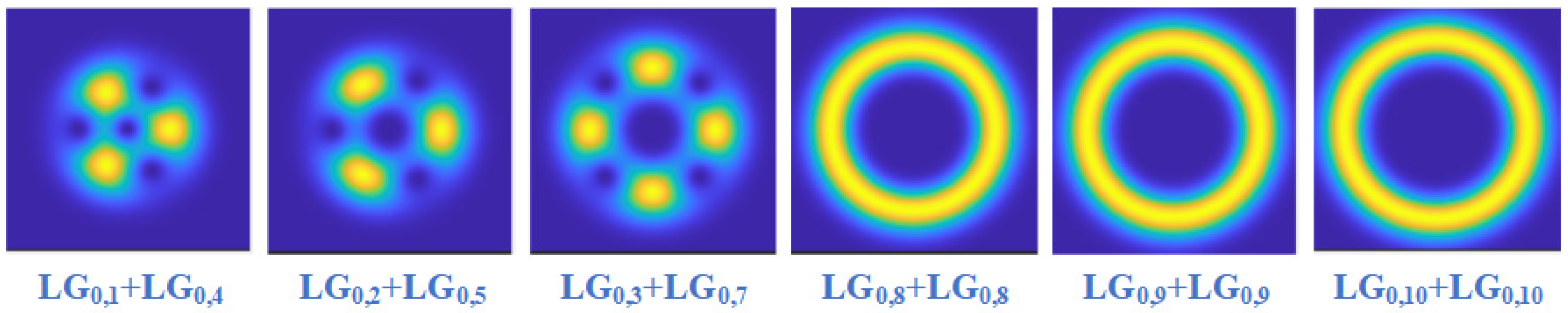
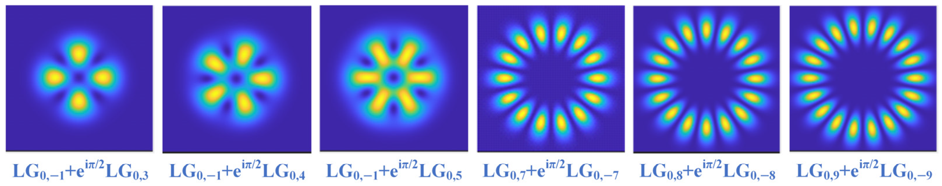
Figure 4 and
Figure 5.
It is worth noting that when two LG beams with opposite mode order signs are superimposed, the chiralities of the two beams are opposite. Therefore, the corresponding double diagonal HG mode superposition state before evolution presents an orthogonal superposition state. When two LG beams with the same mode order signs are superimposed, the chiralities of the two beams are the same. Therefore, the corresponding double diagonal HG mode superposition state before evolution presents a right-handed state.
3. Experimental Setup and Results
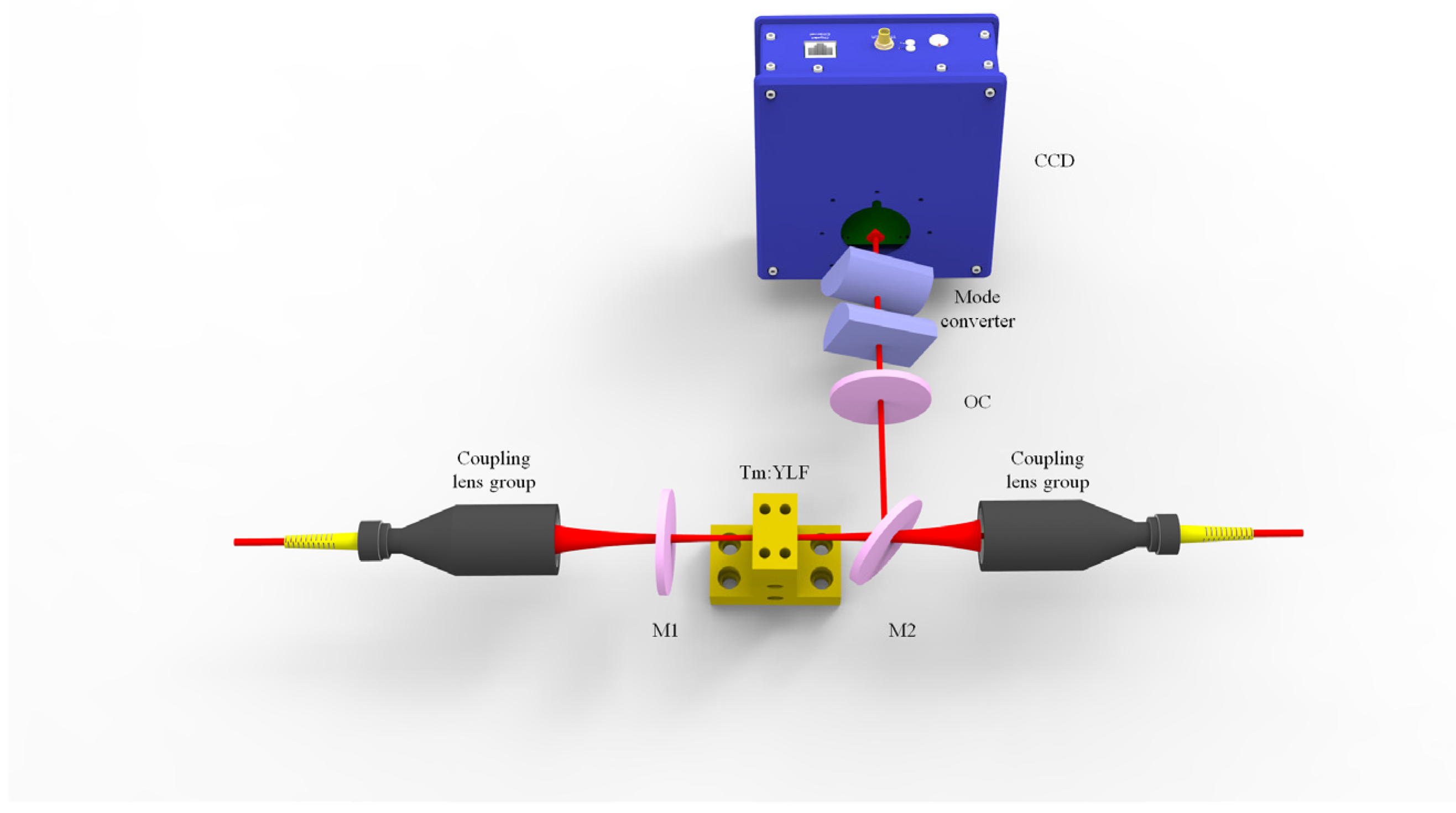
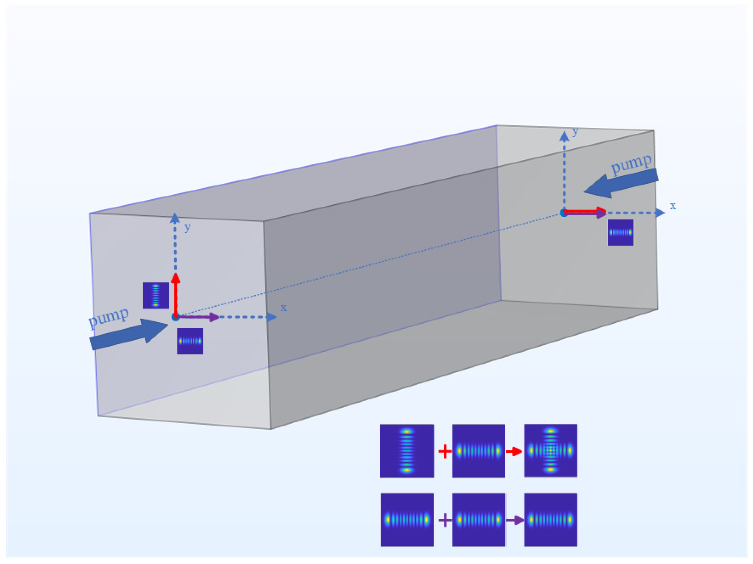
Figure 6 is the experimental device diagram of double LG mode superposition evolution based on astigmatic mode conversion. In this experiment, two laser diodes (LDs) with the wavelength of 792 nm are employed as the pump source. The double-end optical fiber is connected to the coupling lens group. In the coupling lens group, there are two focusing lenses coated with 792 nm anti-reflection film, and the focusing ratio is 25:50. The pump light is focused by the coupling lens group to the front 1/3 of the Tm: YLF crystal. The size of the crystal is 3 × 3 × 12mm
3. The doping concentration of Tm
3+ is 3.5at%. Both end surfaces of the crystal are coated with 1.9 μm and 792 nm anti-reflection film. The crystal is wrapped with indium foil on the side and placed in a copper crystal clip with an external water-cooling tube. The experiment is conducted using a plane-concave cavity. The cavity includes a laser total-reflective plane mirror (M1, HT@792 nm, HR@1908 nm), a dichroic mirror (M2) with the same film system as M1, and a concave laser output mirror (OC, T = 10%, R = 150, HT@1908). The physical length of the resonant cavity is 80 mm. The double-ended off-axis pumping is achieved by moving two coupling lens groups connected to the optical fiber, which are mounted on a finely adjustable five-dimension adjuster. The lens group can be moved in horizontal (
x-axis) and vertical (
y-axis) directions, allowing the generation of horizontal and vertical HG modes. A 1908 nm focusing lens with a focal length of f = 100 mm is installed at the back end of the output mirror, which can effectively alter the beam waist radius to control the Rayleigh distance. An astigmatic mode converter composed of two uncoated cylindrical lenses (f = 25 mm) is added to the rear end of the focusing lens. Moreover, the distance between the two cylindrical lenses is 35.35 mm. Finally, the CCD camera (Beam Profiling Camera, Spiricon Pyrocam III) is placed to record the double HG mode superposition state and the double LG mode superposition state.
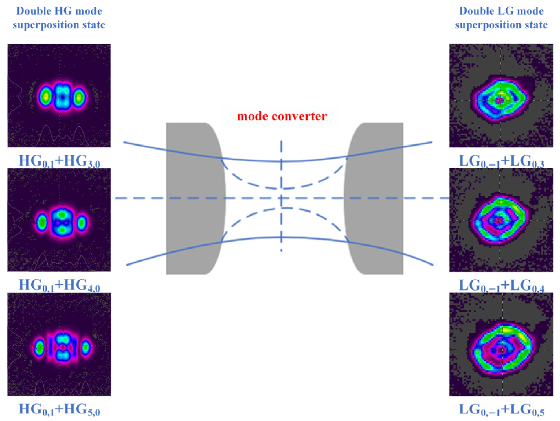
As shown by the red arrows in
Figure 7, the crystal is off-axis pumped in the horizontal and vertical directions, and the HG beams in the horizontal and vertical directions are output at both ends. The off-axis distance of HG beams with a different order at both ends of the crystal are measured, as shown in
Figure 8a. In the process of increasing the horizontal off-axis amount from 0 to 610 μm at the left end of the crystal, the continuous mode output from HG
1,0 to HG
1,0 is realized. In the process of increasing the off-axis distance from 0 to 820 μm in the vertical direction at the right end of the crystal, the continuous mode output of HG
0,1 to HG
0,10 modes is realized. As the off-axis distance increases, the mode order becomes larger. The double HG mode superposition state output with a phase difference of π/2 is realized in the resonant cavity by off-axis pumping the crystal at both ends. Subsequently, an astigmatic mode converter is added to the back end of the resonant cavity. The angles of the two cylindrical lenses are adjusted so that they form a 45° angle with the output light beam from the resonant cavity. Thus, the evolution of the superposition state mode is achieved. The superposition evolution light field diagram is shown in
Figure 9 and
Figure 10.
The evolution of the double vortex superposition state under different conditions is realized by changing the double-end off-axis distance. The HG mode superposition state is generated by double-end off-axis pumping. It has nodal lines in the x and y directions, with the number of nodal lines denoted as m and n, respectively. When m is equal to n, the output HG mode superposition state presents an orthogonal superposition pattern of symmetrical structure. After passing through the astigmatic mode converter, the LG mode superposition state with the opposite mode order is output. The resulting pattern presents a uniformly distributed petal shape with m + n. When m is not equal to n, the output superposition state of the HG mode presents an orthogonal superposition pattern with an asymmetric structure. In such a situation, the LG mode superposition state with the opposite sign and unequal absolute value of the mode order is output. Specifically, it corresponds to the 1 + 3, 1 + 4, 1 + 5 order double LG mode superposition state. The radii of the vortex light spots with different mode orders output by the same resonator are different. When these vortex light spots are superimposed after passing through the cylindrical lens, complete overlap cannot be achieved. Therefore, the pattern presents a double ring.
Based on the above superposition, the off-axis beam with one end off-axis in the vertical direction (
y-axis) is changed to off-axis in the horizontal direction (
x-axis), as shown in
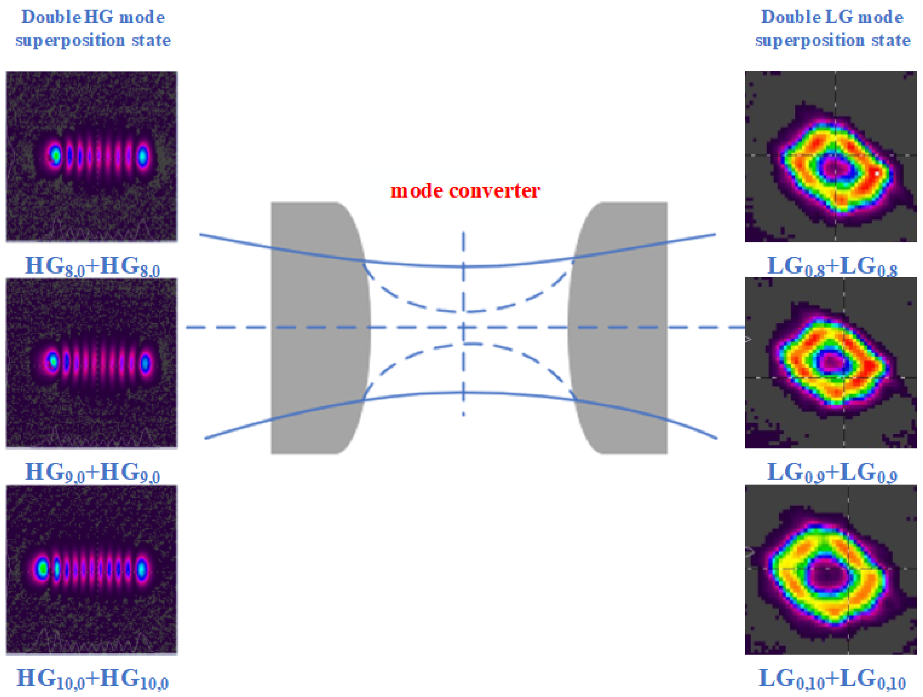
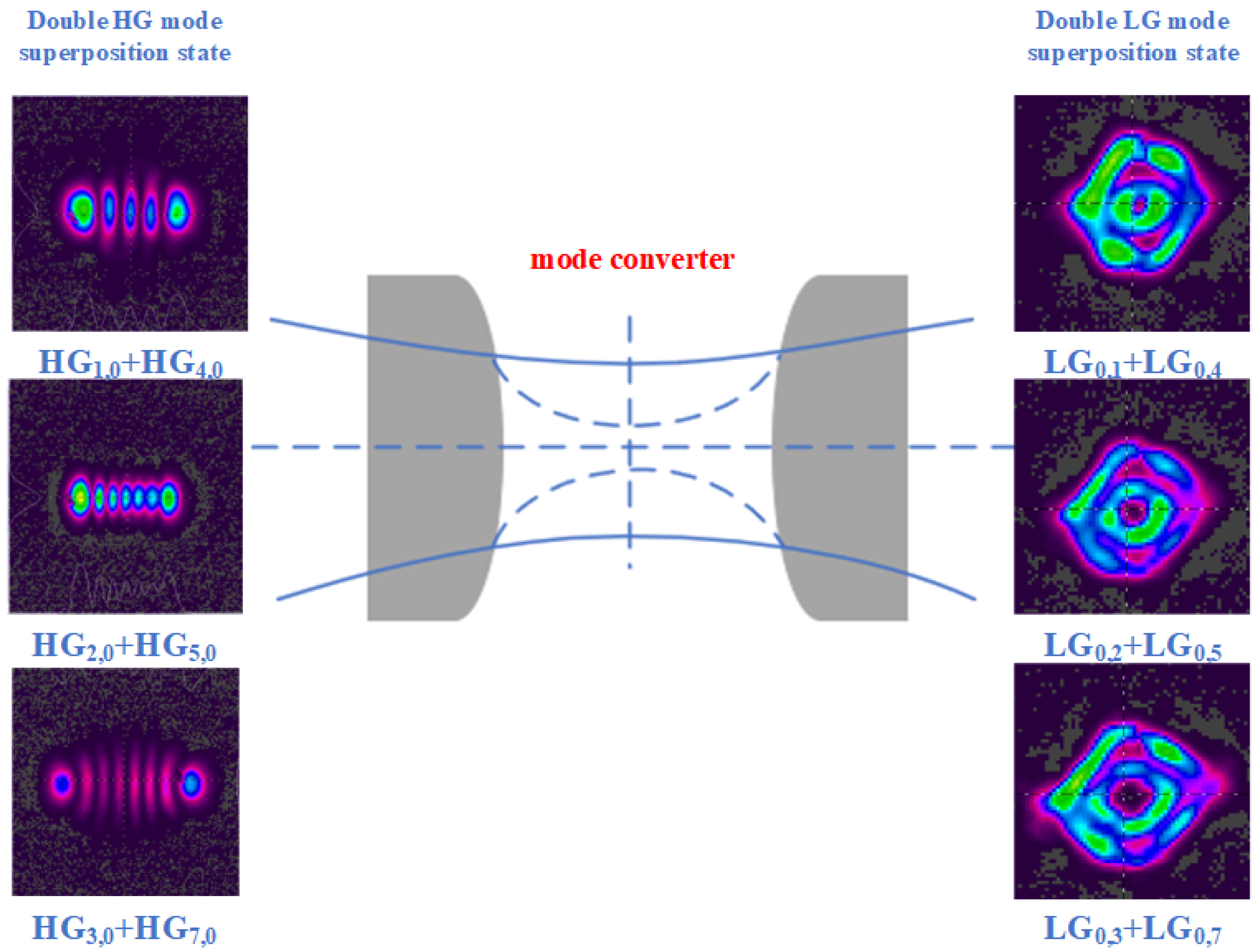
Figure 7 by the purple arrow. By performing double-end off-axis pumping on the crystal, HG beams in the horizontal direction are output at both ends. The off-axis distance of HG beams with a different order at the left and right ends of the crystal are measured, as shown in
Figure 8b. As the horizontal off-axis distance at the crystal’s right end increases from 0 to 840 μm, continuous HG
1,0–HG
10,0 mode output is achieved. It can be seen from
Figure 8 that when HG modes of the same order are generated at both ends of the crystal, the waist positions of the pump beams at the two ends cannot coincide completely. This positional difference will lead to changes in the gain positions of the crystal, which in turn makes the off-axis distances at the left and right ends of the crystal different. For the single side of the crystal, in the two cases of horizontal off-axis and vertical off-axis, the off-axis distance of the HG mode with the same order is not much different. This can also prove that the HG mode generated by off-axis pumping has a stable law. The double HG mode superposition state output is realized by double-end off-axis pumping. Subsequently, an astigmatic mode converter is added at the back end of the resonant cavity to realize the evolution from the double HG mode superposition state to the double LG mode superposition state. The superimposed evolution light field diagram is shown in
Figure 11 and
Figure 12.
By changing the off-axis distance of the two ends, the evolution of the double vortex superposition state in different cases is realized. The HG mode superposition state is generated by double-end off-axis pumping. If the number of transverse nodal lines n of the two HG modes generated at both ends is the same, then the output HG mode superposition state remains in the horizontal state, and the number of nodal lines is n. After passing through the astigmatic mode converter, the LG mode superposition state is output in the same order. The pattern exhibits a circular shape, the light intensity is enhanced, and the phase singularity becomes larger than that prior to the superposition. It is worth noting that due to the inability to fully meet the theoretical placement requirements of the mode converter, the spot shape cannot achieve a theoretically standard symmetrical ring. When the number of transverse nodal lines n of HG beams generated by double-ended off-axis pumping is different, the output HG mode superposition state is in the horizontal direction. Its transverse nodal line number equals that of the larger pre-superposition mode. In such a situation, the LG mode superposition state with the same sign and not equal value of the output mode order is output. Due to the superposition of different mode order beams, the spot radius is different and cannot be completely overlapped, resulting in a double-ring pattern.
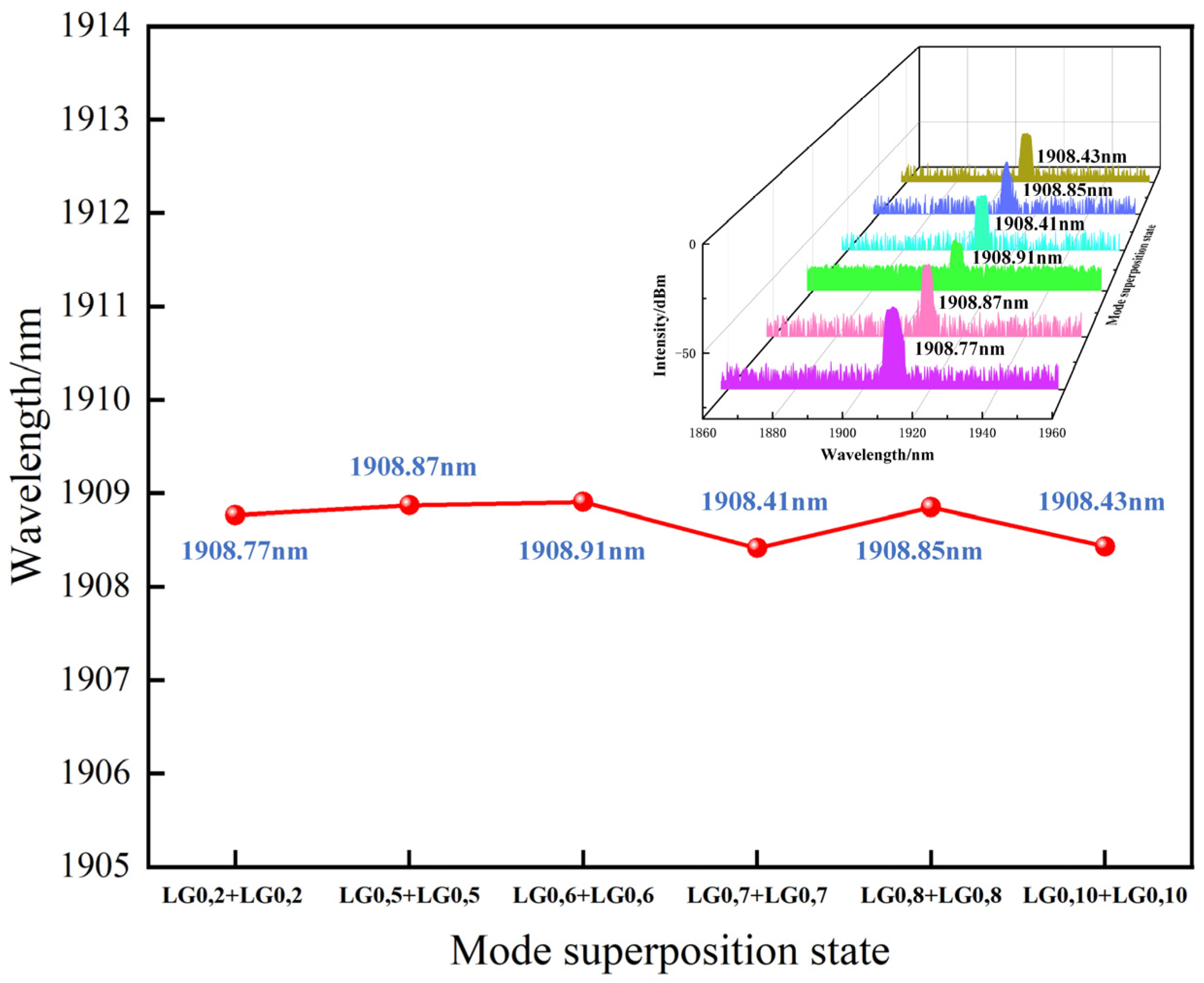
Figure 13 shows the wavelength of the double LG mode superposition state under the different mode superposition conditions. It can be observed that the output wavelength is stabilized near 1908 nm with almost no wavelength shift as the mode order changes.

