Communication

Phase Disturbance Compensation for Quantitative Imaging in Off-Axis Digital Holographic Microscopy

1
School of Optoelectronic Engineering, Changchun University of Science and Technology, Changchun 130022, China
2
Key Laboratory of Advanced Optical System Design and Manufacturing Technology of the Universities of Jilin Province, Changchun University, Changchun 130022, China
*
Author to whom correspondence should be addressed.
Photonics 2025, 12(4), 345; https://doi.org/10.3390/photonics12040345
Submission received: 27 February 2025 / Revised: 15 March 2025 / Accepted: 24 March 2025 / Published: 4 April 2025

Abstract

:
Holographic detection technology has found extensive applications in biomedical imaging, surface profilometry, vibration monitoring, and defect inspection due to its unique phase detection capability. However, the accuracy of quantitative holographic phase imaging is significantly affected by the interference from direct current and twin image terms. Traditional methods, such as multi-exposure phase shifting and off-axis holography, have been employed to mitigate these interferences. While off-axis holography separates spectral components by introducing a tilted reference beam, it inevitably induces phase disturbances that compromise measurement accuracy. This study provides a computational explanation for the incomplete phase compensation issue in existing algorithms and establishes precision criteria for phase compensation based on theoretical formulations. We propose two novel phase compensation methods—the non-iterative compensation approach and the multi-iteration compensation technique. The principles and applicable conditions of these methods are thoroughly elucidated, and their superiority is demonstrated through comparative experiments. The results indicate that the proposed methods effectively compensate for phase disturbances induced by the tilted reference beam, offering enhanced precision and reliability in quantitative holographic phase measurements.

1. Introduction

Digital holography, often integrated with microscopic optical systems, has been widely applied in fields such as biomedical imaging [1,2,3], surface profilometry [4,5,6], vibration analysis [7,8,9], crystal detection [10], and defect inspection [11,12,13]. However, quantitative phase measurement in holography is often compromised by interference from direct current (DC) and twin image term5s, which significantly hinder accurate phase extraction. The primary methods to mitigate these interferences include phase shifting techniques [14,15] and off-axis holography [16,17]. This study focuses on off-axis holography, where phase disturbances in digital off-axis microscopic holography primarily arise from two sources: (1) spherical wave phase disturbances induced by the microscopic system, and (2) phase disturbances caused by the tilted reference beam.
Regarding phase disturbances from microscopic imaging systems, existing research has proposed several solutions, including using identical microscopic systems in both optical paths [18,19], employing telecentric optical configurations [20,21], and developing various numerical compensation algorithms [22,23,24].
This work focuses on addressing phase disturbances induced by the tilted reference beam. Several compensation methods have been proposed to mitigate these phase perturbations, including the full ROI search (FRS) method by Carlos Trujillo et al. [25], the cost function search (CFS) method by Raul Castañeda et al. [26], and the efficient ROI search (ERS) method by Sofia Obando-Vásquez et al. [27].
In this study, we propose two novel phase compensation strategies—a non-iterative method that treats phase disturbances as background illumination inhomogeneity and corrects them through background normalization algorithms, and a multi-iteration compensation algorithm developed to iteratively refine phase corrections and improve accuracy. Furthermore, we provide a frequency-domain analysis to explain the incomplete compensation phenomenon observed in both FRS and frequency shifting methods. This theoretical framework serves as the foundation for our enhanced multi-iteration compensation algorithm, specifically designed to address phase disturbances induced by the tilted reference beam.

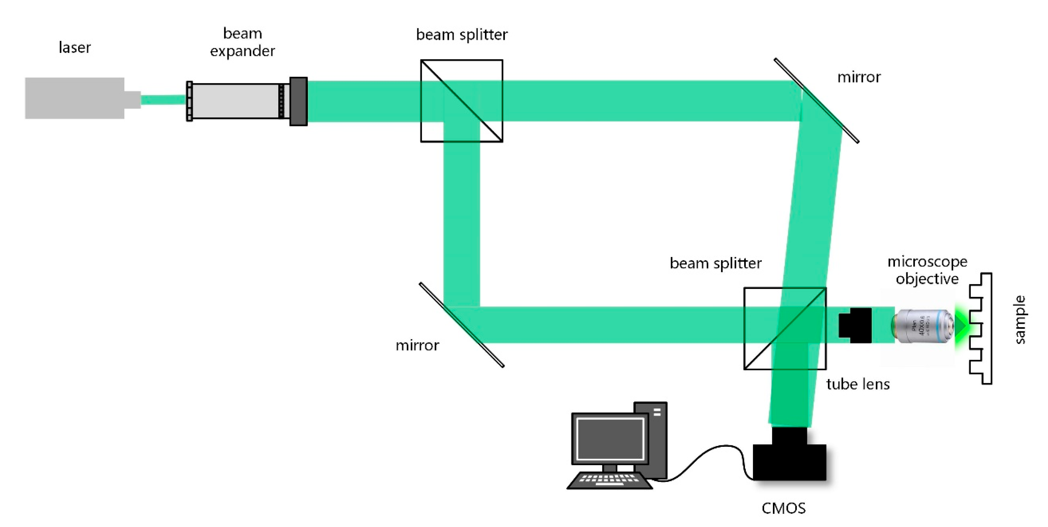
2. Off-Axis Digital Holographic Microscopy

The experimental setup uses a reflection-mode off-axis holographic microscope, as shown in Figure 1. A collimated laser beam is split by a beam splitter into two paths after beam expansion. The object beam, modulated by the sample, is reflected and magnified through the microscopic optical system before recombining with the tilted reference beam at the CMOS detector. The imaging system features a telecentric optical configuration with an infinity conjugate microscope objective (MO) and a unity magnification tube lens, with the CMOS positioned at the focal plane of the tube lens. This configuration eliminates the need for numerical propagation in hologram processing.
In off-axis digital holography, the interference between the object wave O x , y = o x , y e x p [ j φ x , y ] and the reference wave R x , y = r x , y e x p [ j ϕ x , y ] generates the holographic intensity:
I ( x , y ) = R ( x , y ) + O ( x , y ) 2 = R ( x , y ) 2 + O ( x , y ) 2 + R * ( x , y ) O ( x , y ) + R ( x , y ) O * ( x , y )
where φ and ϕ represent phase distributions, and * denotes complex conjugation. Since the reference beam used is a tilted plane wave, Equation (1) can be written as:
I ( x , y ) = R ( x , y ) R * ( x , y ) + O ( x , y ) O * ( x , y ) + exp j 2 π λ sin θ x x + sin θ y y O ( x , y ) + exp j 2 π λ sin θ x x + sin θ y y O * ( x , y )
where θ x and θ y denote the reference beam’s angular deviation from the optical axis, and λ is the wavelength.
Let f x = s i n θ x λ , f y = s i n θ y λ
F exp ( ± j f x 0 x ) O ( x ) = O f x f x 0
O ( x ) is the Fourier transform of O ( x ) . This angular separation induces frequency-domain shifts between the spectral components—the DC term remains centered, while the twin images undergo opposite frequency shifts.
Assuming the object spectrum spans spatial frequency a, the DC term occupies a 2a bandwidth. When the twin image shift exceeds a, spectral isolation enables selective filtering of the +1 order image to eliminate DC and twin image interference.
However, after obtaining the frequency-filtered off-axis hologram, it is essential to recover the frequency shifted object spectrum. While this process can be achieved through precise measurement of the angular separation between reference and object beams as shown in Equation (4), alternative frequency-domain processing approaches exist.
O ( x , y ) = O ( x , y ) R * ( x , y ) R ( x , y ) = O ( x , y ) R * ( x , y ) exp j 2 π λ sin θ x x + sin θ y y
The frequency shifting method involves locating the spectral centroid of the filtered object beam and translating it to zero frequency, which theoretically enables complete compensation of tilt-induced phase disturbances. Nevertheless, the discrete nature of digitally captured holograms introduces inherent limitations. The Fourier transform of discrete samples yields quantized spatial frequency components, fundamentally restricting phase compensation accuracy.
Considering discrete sampling effects, the frequency resolution of our off-axis holographic microscope is determined by:
Δ f x = 1 N Δ x , Δ f y = 1 M Δ y
where Δx, Δy represents the CMOS pixel size, and N × M denotes the sensor array dimensions.
For a tilted plane wave expressed as:
R ( x , y ) = A exp ( j 2 π λ sin θ x x + sin θ y y )
the corresponding spatial frequencies become f x = s i n θ x / λ ,   f y = s i n θ y / λ . Due to the small off-axis angle in off-axis holography, the small-angle approximation allows us to consider sin θθ. The minimum resolvable angular deviation dθ is consequently constrained by the system’s frequency resolution:
d θ = λ d f
This quantization effect explains why residual phase disturbances remain after applying frequency shifting methods when the tilt angle is smaller than dθ. Due to the discretization in the frequency domain, conventional frequency shifting methods cannot fully eliminate the phase disturbances caused by off-axis angles smaller than dθ, resulting in an inability to resolve sub-pixel spectral displacements.

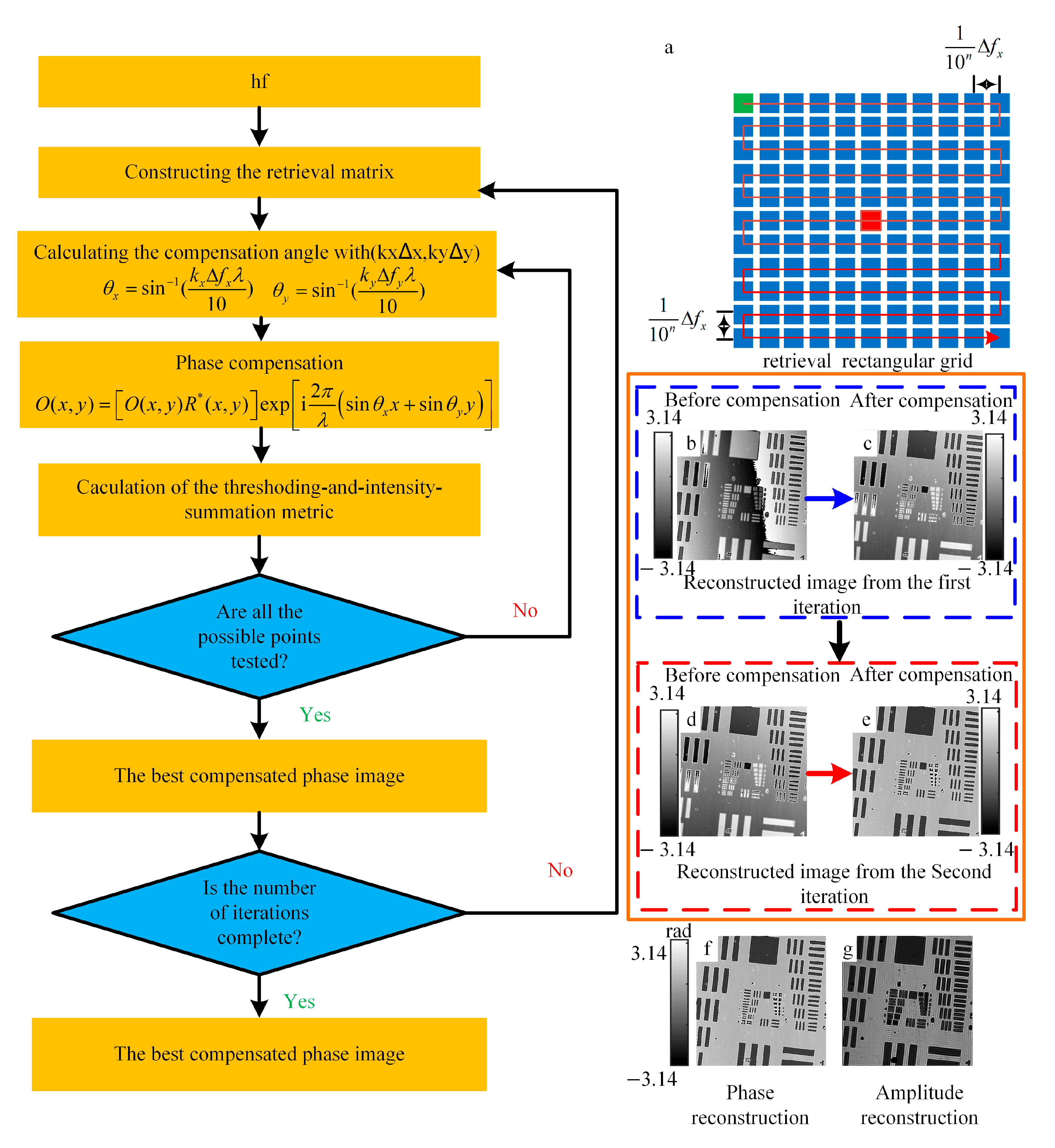
3. Algorithm to Compensation Phase in Off-Axis DHM

The proposed non-iterative background correction method operates through two sequential stages—pre-correction and background correction. As illustrated in Figure 2 the pre-correction stage involves critical processing steps including +1 order diffraction peak identification and application of customized masks. The peak localization and mask dimension determination follow the algorithm described in Ref. [25]. Following spectral filtering, precise +1 order maximum localization and frequency shifting to zero-frequency alignment complete the pre-correction process, whose efficacy fundamentally depends on the residual phase disturbance.
Post pre-correction, the residual phase disturbances can be effectively regarded as background inhomogeneity, enabling the application of advanced background correction techniques. Our implementation employs iterative minimum filtering to extract background components by suppressing sample information, followed by background subtraction from the pre-corrected phase image. The proposed algorithm implements a dual-stage correction strategy:
  • Pre-Correction Stage:
    Adaptive mask-based spatial frequency filtering;
    +1 order peak localization via maximum intensity detection;
    Frequency shifting to zero-frequency alignment.
  • Background Correction Stage:
    Phase disturbance modeling as background variation;
    Iterative minimum filtering for background extraction;
    Background subtraction for final correction.
While this method demonstrates simplicity and feasibility, several critical considerations must be addressed during implementation. When phase wrapping occurs due to phase disturbances induced by the tilted reference beam, phase unwrapping must precede background correction. Furthermore, the method is particularly suitable for sparse samples with limited structural complexity, as minimum filtering may inadequately suppress sample information in dense specimens, compromising background extraction accuracy. This approach cannot completely eliminate the phase disturbances induced by the tilted reference beam.
Given the limited applicability of the aforementioned method, we propose an advanced multi-iteration retrieval approach comprising two stages—pre-correction and iterative refinement. The pre-correction stage follows the same procedure as the background correction method. Subsequently, the multi-iteration retrieval process, as illustrated in Figure 3, initiates with calculating the system’s minimum frequency resolution unit at zero frequency based on wavelength (λ), pixel size (Δ x, Δ y), and pixel count (N, M).
Construct a retrieval grid where the spacing between points in the grid is 1/10 of the discrete Fourier spectral value in that direction. Phase compensation is performed for each matrix element, with corresponding tilt angles calculated as:
θ x = sin 1 ( k x Δ f x λ 10 ) θ y = sin 1 ( k y Δ f y λ 10 )
where k x and k y are matrix indices ranging from 5 to +5, with (0,0) representing the central position. By substituting the compensation angle calculated at the corresponding position in the retrieval grid into Equation (4), the compensation can be accomplished. Upon completing a retrieval step, the optimal compensation is achieved at the current resolution. The optimal compensation position is automatically determined using the mean threshold intensity sum metric method [25], which employs Otsu’s method for threshold selection. Upon completing a retrieval step, the optimal compensation is achieved at the current resolution. The resolution of the retrieval grid constructed at the start of the next iteration is 1/10 of the previous step. As the number of iterations increases, the resolution of the retrieval grid is expressed as f 10 n , where n is the iteration number.

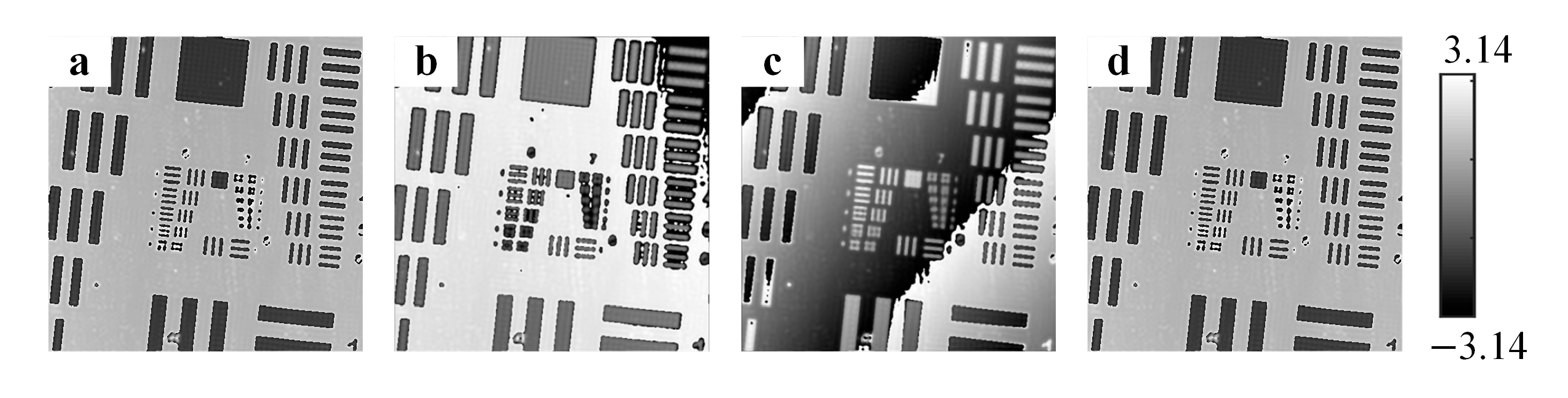
4. Results and Validation

The off-axis holographic system employed in this study features a 532 nm laser source, a 12.5 μm × 12.5 μm pixel size, and a 512 × 512 pixel array. The microscopic configuration incorporates a 10× objective with 0.25 NA within a telecentric optical system.
Figure 4a presents the pre-corrected phase image of a USAF resolution target, while Figure 4b displays the background profile obtained through three iterations of minimum filtering with a 5 × 5 mask. The background-corrected phase image (Figure 4c) is derived by subtracting Figure 4b from Figure 4a. Line profiles in Figure 4d demonstrate the phase correction efficacy, where the red solid line represents pre-corrected phase data exhibiting residual tilt, and the green dashed line shows the background-corrected phase profile with eliminated tilt artifacts. The background correction algorithm processes 512 × 512 holograms in 1.1572 s.
The holographic phase images of the gold layer, which was patterned after being deposited by magnetron sputtering, were corrected using the same method as described for Figure 4. The correction results are shown in Figure 5, where Figure 5a represents the image before correction and Figure 5b represents the image after correction. It can be observed that the tilt phase disturbance has been effectively suppressed.
Comparative analysis of phase compensation methods was conducted using USAF targets under controlled angular variations between reference and object beams. Four methods were evaluated—FRS, ERS, CFS, and our proposed MRS (Multi-iteration Retrieval System).
Figure 6a illustrates FRS compensation results at a 10%Δf frequency resolution precision, revealing incomplete phase correction due to residual angular deviations below 10% of sin 1 ( Δ f λ 10 ) . Even at 1% precision (matching the MRS’s accuracy), FRS demonstrates limitations with larger frequency resolution units.
The ERS approach (Figure 6b) fails to achieve complete compensation despite its computational efficiency. While ERS reduces processing time by limiting the search region to the line connecting +1 order maximum and spectral centroid, this constraint often excludes the optimal compensation point.
The CFS results (Figure 6c) exhibit local optima issues due to non-convex cost functions, despite incorporating optimization algorithms. This fundamental limitation compromises compensation reliability.
Our MRS method (Figure 6d) successfully eliminates phase disturbances through systematic multi-iteration searching. Unlike conventional exhaustive search methods, MRS achieves equivalent precision with only 21% of FRS processing time by implementing iteration depth control.
To quantitatively evaluate the phase compensation effectiveness of several different algorithms, the compensation ratio (CR)is introduced defined as:
C R = θ c x + θ c y θ a x + θ a y
To quantify the compensation error, the phase compensation error (PE) is defined as:
P E = ( θ c x θ a x ) 2 + θ c y θ a y 2 θ a x 2 + θ a y 2
where θ c x and θ c y represent the compensation angles determined by the algorithm, while θ a x and θ a y denote the actual compensation angles required for complete phase disturbance elimination. The actual compensation angles are obtained through an iterative refinement process using the retrieval method, where the search precision is progressively increased until the output phase image stabilizes, indicating convergence to the true compensation angles.
Table 1 summarizes comparative performance metrics obtained on a Windows-based system (i7-9750H CPU @ 2.60 GHz, 16 GB RAM) using Python 3.7.
The results indicate that the performance of the ERS and CFS algorithms is influenced by the off-axis angle. In contrast, both the FRS and MRS methods, being based on exhaustive search techniques, consistently yield the optimal correction results. Notably, the MRS method significantly reduces computational load compared to the FRS method.

5. Conclusions

We have developed two novel phase compensation algorithms specifically designed for telecentric off-axis digital holographic microscopy systems to address phase disturbances induced by reference beam tilt.
The non-iterative approach offers computational simplicity and rapid processing, making it particularly suitable for phase imaging of sparse, small-scale samples. However, its application is limited effectiveness with complex, dense samples. Additionally, this method cannot achieve complete phase compensation.
The multi-iteration retrieval system (MRS) method represents an advancement, achieving optimized compensation accuracy while reducing computational load through multiple iterations. Compared to conventional methods, MRS demonstrates superior performance by significantly decreasing processing time at equivalent precision levels while eliminating residual disturbances. Nevertheless, its application scope is confined to telecentric systems and does not to compensating higher-order aberrations.

Author Contributions

Conceptualization, Y.L.; methodology, Y.L. and W.S.; investigation, W.S.; writing—original draft preparation, W.S. writing—review and editing, L.H., Y.L. and C.X.; data curation, W.S.; project administration, L.H.; funding acquisition, Y.L. All authors have read and agreed to the published version of the manuscript.

Funding

This research was funded by The Technology Innovation Guidance Program of Jilin Provincial Science and Technology Department (20240401077YY).

Institutional Review Board Statement

Not applicable.

Informed Consent Statement

Not applicable.

Data Availability Statement

Conflicts of Interest

The authors declare no financial or personal connections that could influence this study.

References

  1. Sun, J.; Kuschmierz, R.; Katz, O.; Koukourakis, N.; Czarske, J.W. Lensless Fiber Endomicroscopy in Biomedicine. PhotoniX 2024, 5, 18. [Google Scholar] [CrossRef]
  2. Potter, C.J.; Xiong, Z.; McLeod, E. Clinical and Biomedical Applications of Lensless Holographic Microscopy. Laser Photon. Rev. 2024, 18, 2400197. [Google Scholar] [CrossRef]
  3. Wu, Y.; Ozcan, A. Lensless Digital Holographic Microscopy and Its Applications in Biomedicine and Environmental Monitoring. Methods 2018, 136, 4–16. [Google Scholar] [CrossRef] [PubMed]
  4. Shao, S.; Zhou, Z.; Deng, G.; Du, P.; Jian, C.; Yu, Z. Experiment of Structural Geometric Morphology Monitoring for Bridges Using Holographic Visual Sensor. Sensors 2020, 20, 1187. [Google Scholar] [CrossRef]
  5. Quan, C.; Chen, W.; Tay, C.J. Shape Measurement by Multi-Illumination Method in Digital Holographic Interferometry. Opt. Commun. 2008, 281, 3957–3964. [Google Scholar] [CrossRef]
  6. Gyímesi, F.; Füzessy, Z.; Borbély, V.; Ráczkevi, B. Analogue Difference Holographic Interferometry for Two-Wavelength Contouring. Opt. Commun. 2009, 282, 276–283. [Google Scholar] [CrossRef]
  7. de Oliveira, I.; Miyazawa, K. Self-Stabilized Holographic Interferometry for the Measurement of Two-Dimensional Vibrations. Opt. Commun. 2023, 546, 129764. [Google Scholar] [CrossRef]
  8. Shi, H.; Fu, Y.; Quan, C.; Tay, C.J.; He, X. Vibration Measurement of a Micro-Structure by Digital Holographic Microscopy. Meas. Sci. Technol. 2009, 20, 065301. [Google Scholar] [CrossRef]
  9. Matsuda, K.; Ye, B.Q.; Fukuchi, N.; Okamoto, H.; Hara, T. Holographic Vibration Measurements of Rough Surfaces Using a LCSLM. Opt. Commun. 2007, 275, 53–56. [Google Scholar] [CrossRef]
  10. Huang, H.; Huang, H.; Zheng, Z.; Gao, L. Insights into infrared crystal phase characteristics based on deep learning holography with attention residual network. J. Mater. Chem. A 2025, 13, 6009–6019. [Google Scholar] [CrossRef]
  11. Seo, K.B.; Kim, B.M.; Kim, E.S. Digital Holographic Microscopy Based on a Modified Lateral Shearing Interferometer for Three-Dimensional Visual Inspection of Nanoscale Defects on Transparent Objects. Nanoscale Res. Lett. 2014, 9, 471. [Google Scholar] [CrossRef] [PubMed]
  12. Fu, Y.; Zuo, P.; Tian, L.; Li, H.; Zhong, K.; Huang, Y.; Ma, B.; Yan, Z. Quantitative Detection of Internal Defects in Objects Using Holographic Double Exposure. Opt. Laser Technol. 2024, 168, 109985. [Google Scholar] [CrossRef]
  13. Trivedi, V.; Joglekar, M.; Mahajan, S.; Patel, N.; Chhaniwal, V.; Javidi, B.; Anand, A. Digital Holographic Imaging of Refractive Index Distributions for Defect Detection. Opt. Laser Technol. 2019, 111, 439–446. [Google Scholar] [CrossRef]
  14. Qin, W.; Yang, X.; Li, Y.; Peng, X.; Yao, H.; Qu, X.; Gao, B.Z. Two-Step Phase-Shifting Fluorescence Incoherent Holographic Microscopy. J. Biomed. Opt. 2014, 19, 060503. [Google Scholar] [CrossRef]
  15. Qiu, P.; Wang, H.; Jin, H.; Li, Y.; Shi, Y. Study on the Simplified Phase-Shifting Digital Holographic Microscopy. Optik 2010, 121, 1251–1256. [Google Scholar] [CrossRef]
  16. Picazo-Bueno, J.Á.; Ketelhut, S.; Schnekenburger, J.; Micó, V.; Kemper, B. Off-Axis Digital Lensless Holographic Microscopy Based on Spatially Multiplexed Interferometry. J. Biomed. Opt. 2024, 29, S22715. [Google Scholar] [CrossRef]
  17. Zhong, Z.; Zhao, H.; Cao, L.; Shan, M.; Liu, B.; Lu, W.; Xie, H. Automatic Cross Filtering for Off-Axis Digital Holographic Microscopy. Results Phys. 2020, 16, 102910. [Google Scholar] [CrossRef]
  18. Wang, H.; Yu, M.; Jiang, Y.; Zhu, Q.; Liu, F. Point Spread Function and Lateral Resolution Analysis of Digital Holographic Microscopy System. Opt. Commun. 2014, 322, 90–96. [Google Scholar] [CrossRef]
  19. Mann, C.J.; Yu, L.; Lo, C.-M.; Kim, M.K. High-resolution quantitative phase-contrast microscopy by digital holography. Opt. Express 2005, 13, 8693–8698. [Google Scholar] [CrossRef]
  20. Doblas, A.; Sánchez-Ortiga, E.; Martínez-Corral, M.; Saavedra, G.; Andrés, P.; Garcia-Sucerquia, J. Shift-variant digital holographic microscopy: Inaccuracies in quantitative phase imaging. Opt. Lett. 2013, 38, 1352–1354. [Google Scholar] [CrossRef]
  21. Sánchez-Ortiga, E.; Doblas, A.; Saavedra, G.; Martínez-Corral, M.; Garcia-Sucerquia, J. Off-Axis Digital Holographic Microscopy: Practical Design Parameters for Operating at Diffraction Limit. Appl. Opt. 2014, 53, 2058–2066. [Google Scholar] [CrossRef] [PubMed]
  22. He, X.; Nguyen, C.V.; Pratap, M.; Zheng, Y.; Wang, Y.; Nisbet, D.R.; Williams, R.J.; Rug, M.; Maier, A.G.; Lee, W.M. Automated Fourier Space Region-Recognition Filtering for off-Axis Digital Holographic Microscopy. Biomed. Opt. Express 2016, 7, 3111–3123. [Google Scholar] [CrossRef] [PubMed]
  23. Wang, Z.; Qu, W.; Wen, Y.; Yang, F.; Asundi, A. A New Phase Error Compensation Method in Digital Holographic Microscopy. In Proceedings of the International Conference on Experimental Mechanics, Singapore, 15–17 November 2014; pp. 542–549. [Google Scholar]
  24. Di, J.; Zhao, J.; Sun, W.; Jiang, H.; Yan, X. Phase Aberration Compensation of Digital Holographic Microscopy Based on Least Squares Surface Fitting. Opt. Commun. 2009, 282, 3873–3877. [Google Scholar] [CrossRef]
  25. Trujillo, C.; Castañeda, R.; Piedrahita-Quintero, P.; Garcia-Sucerquia, J. Automatic Full Compensation of Quantitative Phase Imaging in Off-Axis Digital Holographic Microscopy. Appl. Opt. 2016, 55, 10299–10306. [Google Scholar] [CrossRef] [PubMed]
  26. Castaneda, R.; Doblas, A. Fast-Iterative automatic reconstruction method for quantitative phase image with reduced phase perturbations in off-axis digital holographic microscopy. Appl. Opt. 2021, 60, 10214–10220. [Google Scholar] [CrossRef]
  27. Obando-Vásquez, S.; Trujjillo, C. Computationally Efficient Phase Aberration Compensation Method for Digital Holographic Microscopy of Biological Samples; Optica Publishing Group: Washington, DC, USA, 2021. [Google Scholar]
Figure 1. Off-axis holography optical path diagram.
Photonics 12 00345 g001
Figure 2. Pre-correction method block diagram. (a) Off-axis DHM hologram, (b) Fourier Spectrum of the DHM hologram, (c) Filtering mask for the spatial filtering, (d) Fourier Spectrum of the +1 diffracting order, (e) Reconstructed phase image.
Photonics 12 00345 g002
Figure 3. Multiple retrieval method flowchart. (a) retrieval rectangular grid, (b) Initial retrieval input image, (c) Initial retrieval output image, (d) Second round retrieval input image, (e) Second-round retrieval output image, (f) Phase reconstruction map from the algorithm, (g) Amplitude reconstruction map from the algorithm.
Photonics 12 00345 g003
Figure 4. Background correction phase images. (a) preprocessed phase image, (b) background image, (c) corrected result, and (d) comparison before and after correction.
Photonics 12 00345 g004
Figure 5. Background correction of holographic phase images for the gold layer patterned after magnetron sputtering deposition. (a) Phase image before correction. (b) Phase image after correction.
Photonics 12 00345 g005
Figure 6. Reconstructed phase images of phase USAF target of FRS for four different algorithms: FRS (a), ERS (b), CFS (c), and MRS (d).
Photonics 12 00345 g006
Table 1. Comparison of FRS, ERS, CFS, and MRS.
FRSERSCFSMRS
Image size512 × 512
Compensation angles(0.04377, 0.06417)(0.02362, 0.04638)(0.02655, 0.04138)(0.04377, 0.06417)
Compensation rate10.650.631
phase compensation error00.3430.3680
Processing(s)28.47321.94213.74766.3729
Image size512 × 512
Compensation angles(0.04673, 0.04197)(0.04673, 0.04197)(0.02177, 0.03771)(0.04673, 0.04197)
Compensation rate110.671
phase compensation error000.4030
Processing(s)28.14921.77383.21836.2411
Image size512 × 512
Compensation angles(0.02477, 0.01176)(0.01955, 0.009739)(0.02477, 0.01176)(0.02477, 0.01176)
Compensation rate10.8211
phase compensation error00.20400
Processing(s)29.17851.86613.37766.7331
Disclaimer/Publisher’s Note: The statements, opinions and data contained in all publications are solely those of the individual author(s) and contributor(s) and not of MDPI and/or the editor(s). MDPI and/or the editor(s) disclaim responsibility for any injury to people or property resulting from any ideas, methods, instructions or products referred to in the content.

