Abstract
Optical chaos generated by a semiconductor laser under cascaded optical injection is experimentally and numerically investigated. A semiconductor slave laser under continuous-wave optical injection from a master laser is employed as the chaotic laser. The chaotic output optically injects a third laser to enhance the chaotic properties. Using three semiconductor lasers coupled in a master-slave configuration without any delay-based components, optical chaos is generated without any time-delay signatures present. Flat broadband chaos is observed with standard and effective bandwidths reaching six and three times the relaxation resonance frequency of the semiconductor laser, respectively. For simultaneous flat and broadband chaos, the chaotic optical injection of the second stage is adjusted for weak injection strength and a high positively detuned frequency.
1. Introduction
Optical chaotic oscillations are deterministic, irregular pulsations in the output intensity of the laser field that are long-term unpredictable due to their high sensitivity to initial conditions [1,2]. Optical chaos has found applications in private optical communications [3], secure key distribution [4], random bit generation [5], chaotic lidar [6,7], chaotic radar [8,9], optical time-domain reflectometry [10], and chaos computing [11,12]. When perturbed, a semiconductor laser can generate various nonlinear dynamics in its output intensity, including chaotic dynamics. Chaos has been generated by perturbing the laser through direct modulation of the driving current of the laser [13,14], optical feedback [15], optoelectronic feedback [16], optical injection [17], and various hybrid configurations of these methods [18,19,20,21,22,23].
Ideal optical chaotic dynamics exhibit a complex time series, high chaotic carrier frequency, broad chaotic bandwidth, featureless chaotic microwave spectrum, and a signature-free autocorrelation function. Deviation from these favorable characteristics of ideal optical chaotic oscillation degrades the performance of the chaotic system in the aforementioned applications. A narrow chaotic bandwidth limits the maximum data rate in chaotic data transmission and in random bit generation as well as the range resolution of chaotic lidars and chaos-based time domain reflectometers [24]. A non-flat chaotic spectrum or the presence of a signature in the autocorrelation function of a chaotic time series compromises security in private chaotic transmission, reduces randomness in random bit generation, and causes range ambiguity in chaotic ranging applications [25,26]. Furthermore, it allows for the projection of high-dimensional attractors onto reduced dimensional phase space reducing the complexity of the chaos generated by the system [27].
Significant efforts have been made to enhance the properties of the chaotic oscillations induced by a perturbed semiconductor laser. Chaotic dynamics generated by a perturbed semiconductor laser have bandwidths that are limited by the relaxation resonance of the semiconductor laser and generally have low spectral flatness [28]. Moreover, chaotic dynamics generated by delay-based configurations, while supporting high-dimensional chaos, introduce periodicity into the system and show evident signatures at multiples of the delay time in the autocorrelation function of the chaotic time series, termed the time-delay signature (TDS) [29]. To enhance the chaotic bandwidth, the bandwidth-enhancing effect of optical injection was utilized on chaos generated by a laser under optical feedback [18]. The bandwidth-enhancing effect was achieved by continuous-wave optical injection [30], chaotic optical injection [31], or strongly modulated optical injection [32]. It has been demonstrated that chaotic optical injection into a continuous-wave laser performs better in terms of bandwidth enhancement and spectral flatness [33]. To suppress the TDS in delay-based chaos generation configurations, a multitude of noteworthy TDS concealment schemes have been proposed. These schemes include TDS concealment by carefully choosing the operating parameters of the laser under optical feedback [34]; TDS concealment by adding optical injection, such as continuous-wave (CW) optical injection into a chaotic laser [35], dual-beam CW optical injection into a chaotic laser [36,37], chaotic optical injection into a CW laser [38], dual-beam chaotic optical injection into a CW laser [39,40], and cascaded chaotic optical injection [24,41]; TDS concealment utilizing different feedback mechanisms, such as frequency-detuned grating feedback [42], phase-conjugate feedback [43], mutually coupled lasers under optical feedback [44,45], dual-loop optical feedback [46], and phase-modulated dual-path optical feedback [47,48,49]; and TDS concealment through post-processing the chaotic output, such as electrical heterodyning [50], incoherent delayed self-interference [51], and adding a fiber ring resonator [52]. Some of these schemes have also been extended to other types of lasers, such as vertical-cavity surface-emitting lasers, nanolasers, discrete-mode lasers, and spin-polarized vertical-cavity surface-emitting lasers [53,54,55,56,57,58].
Recently, optical chaos generated by optical injection has been demonstrated to have potential in low-dimensional dynamic applications [59,60]. Inherently signature-free optical chaos has been demonstrated in cascaded optically injected lasers [61], destabilized period-one dynamic of an optically injected laser [62,63], and intensity-modulated optical injection [64]. This paper presents for the first time a comprehensive study of the properties of optical chaos generated by a cascaded optically injected semiconductor laser configuration, based on the rate equation model. Chaotic properties, including the standard bandwidth, effective bandwidth, spectral flatness, autocorrelation function, and permutation entropy, are systematically analyzed. Chaos is initially generated through optical injection in a master slave configuration, and the chaotic output is then injected into a third laser to enhance the chaotic properties through the careful selection of operating parameters. Unlike other schemes that use cascaded optically injected laser configurations [18,22,24], this work eliminates all feedback loops in the optical chaos generation process. As a result, no residual correlation in the intensity or phase of the chaotic output is observed, which is typical of similar schemes where chaos is generated through optical feedback in the first stage [65]. This approach allows for enhancement in the bandwidth and spectral flatness without the limitations imposed by the need for simultaneous optimized operation for TDS suppression [66]. Furthermore, this work can be used to extend the capabilities of chaotic waveforms generated by configurations without delay-based mechanisms.
Following this introductory section, the experimental setup and chaos generated by cascaded optical injection are demonstrated in Section 2. The theoretical model used to simulate the cascaded optical injection configuration is detailed in Section 3. Section 4 discusses the chaotic properties of chaos generated by the cascaded optical injection scheme through its standard bandwidth, effective bandwidth, spectral flatness, autocorrelation function, and permutation entropy. The paper is concluded in Section 5, where a summary of the results is presented.
2. Experimental Setup and Demonstration
Figure 1 shows the experimental setup to generate optical chaos by cascaded optical injection. In the first optical injection stage, the master laser (ML) optically injects the first slave laser (SL1) into chaotic dynamics. The ML injects SL1 with injection strength ξ1 defined as the square root of the power ratio between the ML signal and the free-running SL1 signal and a frequency detuning f1 = vML − vSL1, where vML and vSL1 are the ML and SL1 free-running optical frequencies, respectively. In the second optical injection stage, the chaotic output of the first slave laser (SL1) optically injects the second slave laser (SL2). The chaotic output of SL1 injects SL2 with injection strength ξ2 defined as the square root of the power ratio between the SL1 signal and the free-running SL2 signal and a frequency detuning f2 = vSL1 − vSL2, where vSL2 is the SL2 free-running optical frequency. The three lasers used are single-mode DFB lasers with integrated thermoelectric coolers and are packaged in separate 14-pin butterfly packages. The lasers are driven by a low-noise laser controller (Newport, LDC-3916, Irvine, CA, USA) for current and temperature stabilization. To avoid unwanted feedback, the ML (JDS Uniphase, CQF935/216.5, Milpitas, CA, USA) is packaged with an optical isolator, while the optical circulator provides further protection. The slave lasers (Qphotonics, QDFBLD-1550-5-1, Ann Arbor, MI, USA) are not packaged with built-in optical isolators to allow for optical injection. A combination of a variable optical attenuator (Thorlabs, VOA50-APC, Newton, NJ, USA) and a 90:10 fiber splitter is used to adjust the injection strength of the first optical injection stage. An optical power meter measures the amount of optical injection from the reference arm of the fiber splitter measuring P1ref. Similarly, to adjust for the optical injection strength of the second optical injection stage, another set of optical components is used: a variable optical attenuator, a fiber splitter, an optical circulator, and an optical power meter measuring P2ref from the reference arm of the fiber splitter. All components shown in the layout are terminated with FC/APC fiber connectors to minimize reflection losses.
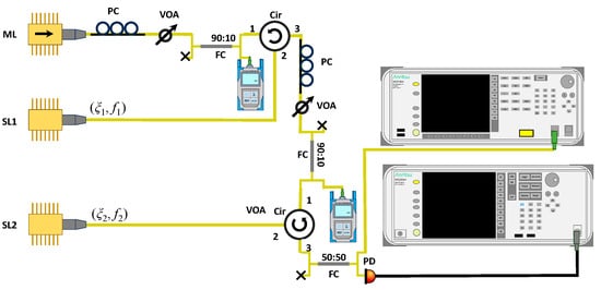
Figure 1.
Experimental setup of the cascaded optically injected semiconductor laser setup. ML, master laser; SL1, the first slave laser; SL2, the second slave laser; VOA, variable optical attenuator; PC, polarization controller; Cir, optical circulator; FC, fiber coupler; PD, photodetector.
The detuning frequency between the master and slave lasers is adjusted by varying the operating temperature for coarse detuning frequency adjustments while the operating current of the laser is used for fine detuning frequency adjustments. The output is split using a 50:50 fiber splitter, with one arm directed to an optical spectrum analyzer (Anritsu, MS9740A, Kanagawa, Japan) that has a spectral resolution of 0.03 nm to monitor the optical spectrum. The intensity output is monitored by a microwave spectrum analyzer (Anritsu, MS2830A) after detection and amplification from a photodiode with a 3dB bandwidth of 38 GHz (Discovery Semiconductor, DSC20S, Ewing Township, NJ, USA) and a microwave amplifier with frequency 0.01–26.5 GHz (HP, 83006A, Palo Alto, CA, USA), respectively. The threshold currents of the master laser, the first slave laser, and the second slave laser are, respectively, 12 mA, 12 mA, and 9 mA. The injection currents of the master laser, the first slave laser, and the second slave lasers are set to 35 mA generating an output power of 3.6 mW, 1.74 mW, and 1.6 mW, respectively. The temperatures of the master laser, the first slave laser, and the second slave lasers are set to 24.5 °C, 24.6 °C, and 24.4 °C, respectively. Under these conditions, the relaxation oscillation frequencies of the first and second slave lasers are 10 GHz. The detuning frequency between the master and slave laser for the first optical injection stage is 5.5 GHz while the detuning frequency between the master laser and the second slave laser for the second optical injection stage is 40 GHz. Measured powers of P1ref = 88 μW and P2ref = 87 μW are recorded for the first and second optical injection stages respectively.
Figure 2 shows the chaotic output of the cascaded optical injection configuration. The black curve indicates the chaotic spectrum resulting from the first optical injection stage. The red curve indicates the chaotic output from the second optical injection stage when the second slave laser is under chaotic optical injection. The grey curve corresponds to the noise-floor level. A typical chaotic spectrum is observed from the output of the first optical injection stage where the spectrum peaks around the relaxation resonance frequency of the slave laser and rapidly decreases towards the noise floor.
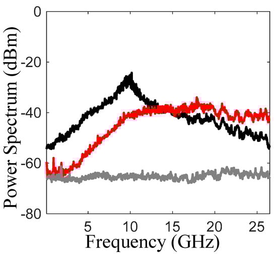
Figure 2.
Experimentally obtained microwave spectra of the chaotic outputs from the cascaded optical injection setup. The black curve indicates the chaotic spectrum from the first optical injection stage. The red curve indicates the chaotic output from the second optical injection stage when the second slave laser is under chaotic optical injection. The grey bottom curve corresponds to the noise-floor level. The standard bandwidths of chaos generated from the first and second optical injection stages are 11.5 GHz and 20.5 GHz, respectively.
The output of the second laser when injected by the output of the first optical injection stage shows a much flatter chaotic spectrum. The chaotic spectrum observed in these experiments is limited by our detection apparatus with a maximum detection bandwidth of 26.5 GHz. Nevertheless, an enhancement in the standard chaotic bandwidth of the optical injected laser from 11.5 GHz for chaos generated by the first optical injection stage to 20.5 GHz for chaos generated by the second optical injection stage is observed. The standard bandwidth of chaos is defined in the next section.
3. Numerical Model
A numerical study is conducted to confirm the chaos observed in our cascaded optical injection experiments and avoid the limitation in the detection apparatus. The numerical model of the cascaded optically injected semiconductor laser system is described by a set of coupled nonlinear rate equations relating the normalized complex intracavity optical field amplitude, a, to the normalized charge carrier density,
. In the following equations, the subscripts 1 and 2 represent the output of the first and second optical injection stages, respectively [67].
where a1 and correspond to the complex intracavity optical field amplitude and normalized charge carrier density of the first optically injected laser, SL1. The second optically injected laser, SL2, is represented by the a2 and corresponding to the complex intracavity optical field amplitude and normalized charge carrier density.
The laser intrinsic parameters are taken to be identical for the two slave lasers, where the lasers are operated at a normalized bias current of = 1.222. The other parameters are extracted experimentally from a DFB semiconductor laser [68], where the linewidth enhancement factor b = 3.2, cavity decay rate γc = 5.36 × 10¹¹ s−1, spontaneous carrier relaxation rate γs = 5.96 × 10⁹ s−1, differential carrier rate γn = 7.53 × 10⁹ s−1, and nonlinear carrier relaxation rate γp = 1.91 × 10¹⁰ s−1. Langevin fluctuating force terms F1 and F2 model spontaneous emission noise of SL1 and SL2, respectively, they are set to zero in the work unless otherwise specified. For the parameters specified, the corresponding relaxation resonance frequency of the lasers is 10.25 GHz. The rate Equations (1)–(4) are solved numerically by a second-order Runge–Kutta integration, with a time step of 2.38 ps and a duration of 1.25 μs or longer to yield the intensity |a1|2 and |a2|2. The Fourier transform of the chaotic time series is taken to calculate the chaotic power spectra.
Two bandwidth definitions are used to evaluate the chaotic bandwidth of the generated spectra. The first definition is the standard bandwidth (SBW) which corresponds to the frequency span from DC to the maximum frequency where 80% of the total spectral power resides. The second definition is the effective bandwidth (EBW) which corresponds to the sum of the spectral spans of the discrete spectral components that account for 80% of the total power [69]. The standard bandwidth gives a measure of the maximum oscillation component in the spectra. On the other hand, the effective bandwidth distinguishes between chaotic states and other dynamical states that are associated with a narrow EBW. Furthermore, the EBW gives a measure of the effective frequency region in the broadband chaotic spectra and the spread of the dominant frequency components of the chaotic spectra. Therefore, the EBW is always smaller than the SBW.
The flatness of the chaotic spectrum gives a measure of the periodicity of the chaotic spectrum and is an alternative measure of the maximum Lyapunov exponent. Here, the flatness of the chaotic output spectrum is evaluated by two definitions. The first definition corresponds to the difference in dB between the maximum and minimum values within the effective bandwidth. The second definition is the spectral flatness (SF) calculated by dividing the geometric mean of the power spectrum by the arithmetic mean of the power spectrum by the following formula [43]:
where P(fn) represents the magnitude of the power at the frequency component fn, and N represents the total number of frequency components of the power spectrum. The spectral flatness takes values between one and zero, where one indicates a perfectly flat spectrum and zero indicates a pure spectral tone. Here, the SF of the chaotic output spectrum is evaluated for the frequency components of the power spectrum within the EBW.
To calculate the autocorrelation function of the chaotic time series the following formula is used on the optical intensity of the laser output, where τ is the delay time, and <•> denotes the time average:
The normalized permutation entropy (PE) is evaluated to quantify the complexity of the chaotic time series generated by a cascaded optically injected semiconductor laser [70]. The PE captures the order of the relation between the elements in a time series and extracts the probability distribution of each ordinal pattern. Define the embedding dimension (D), which gives the length of the vector segments of the time series of which ordinal patterns will be assigned, and the embedding time delay (τe), which gives the number of periods between elements of each of the new time-series vectors of length D which is an integer multiple of the sampling period Ts. For the intensity time series |a(t)|2 of length T sampled with a period Ts, the number of time-series vectors Xj = (|a(t)|2, |a(t + τe)| …, |a(t + (D − 1)τe)|2) will be j = 1, …, T − (D − 1)τe. The coordinates of the vector Xj are sorted in ascending order according to their values as [|a(t + (r1 − 1)τe)|2 ≤ |a(t + (r2 − 1)τe)|2 ≤ … ≤ |a(t + (rD − 1)τe)|2] and are mapped to an ordinal pattern π = (r1, …, rD) which is one of the permutations of X with D dimensions. We define the probability distribution p(π) for all possible D! permutations for the ordinal patterns P by
where # is the number. From the probability p(π) the permutation entropy h[P] and the normalized permutation entropy H[P] are defined as
The normalized permutation entropy H[P] takes values between one and zero, where one represents a completely stochastic time series and zero represents a completely predictable time series.
4. Discussion
Figure 3a shows the chaotic output of the first optical injection stage from the cascaded optically injected laser. The optically injected semiconductor laser SL1 is injected by a continuous-wave signal from the master laser at (ξ1, f1) = (0.05, 6.25 GHz). The emission intensity of the output from the optically injected laser SL1 shows chaotic irregular pulsation and is illustrated in Figure 3a-i. The corresponding power spectrum is shown in Figure 3a-ii, showing a prominent peak at the relaxation resonance frequency of the semiconductor laser SL1. The SBW is evaluated to be 12.5 GHz and the EBW is evaluated to be 7.45 GHz, as highlighted by the dashed vertical line and the red shaded area, respectively. The chaotic output exhibited a flatness of 10 dB and SF of 0.65. The chaotic properties closely match the chaotic properties observed experimentally in chaos generated by a semiconductor laser with continuous-wave optical injection as demonstrated in Figure 2. Figure 3a-iii shows the autocorrelation function of the chaotic state generated in the first optical injection stage. The oscillation in the autocorrelation function quickly diminishes as the delay time is increased showing peaks at time delays that are multiples of the relaxation resonance period of the laser. Due to the absence of feedback loops, no residual peaks appear in the autocorrelation function signifying no periodicity in the chaotic intensity waveform. Figure 3a-iv shows the normalized permutation entropy H[P] of the intensity time series as a function of the embedding time delay and embedding dimensions for D = 4 (black), D = 5 (red), D = 6 (blue), and D = 7 (gray). Several minima are observed at subharmonics of the relaxation resonance frequency which rapidly vanish as τe is increased. The chaotic state shown in Figure 3a is found at the center of the chaotic region in the mapping of an optically injected laser with respect to the injection strength and detuning frequency [71]. This chaotic state at the output of the optically injected laser, SL1, exhibits the broadest bandwidth and flattest spectrum achievable from the first optical injection stage and will henceforth serve as the chaotic injection signal. Figure 3b shows SL2 output when the optical injection of the first optical injection stage is set at (ξ1, f1) = (0.05, 6.25 GHz) while the second optical injection stage is set at (ξ2, f2) = (0.07, 48 GHz). Figure 3b–i shows rapid fluctuation in the output intensity of SL2 as compared to the output intensity of SL1, shown in Figure 3a–i. Furthermore, the correlation between the chaotic outputs of SL1 and SL2 is relatively weak [61]. The corresponding power spectrum shows prominent peaks around the relaxation resonance frequency of SL1, the detuning frequency, the optical injection-enhanced relaxation resonance frequency of SL2 [72], and frequency components arising from the nonlinear frequency mixing of these spectral components. The enhancement of the relaxation resonance frequency of the slave laser under strong optical injection has been mapped in a previous effort for a laser with the same intrinsic parameters in the unlocked and locked nonlinear dynamic regions [72]. Broad chaotic bandwidth is observed where the peak at the relaxation resonance frequency of SL1 and the other prominent peaks are close in magnitude. At this operating point, the SBW is evaluated to be about 50 GHz while the EBW is evaluated to be about 35.5 GHz, as highlighted by the dashed vertical line and the red shaded area, respectively. The chaotic output exhibited a flatness of 9 dB and a SF of 0.85 at this operating point.
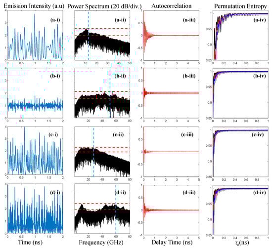
Figure 3.
Chaotic output of the cascaded optically injected semiconductor laser at different operating conditions (i) Intensity time series, (ii) power spectra, (iii) autocorrelation function, (iv) permutation entropy of the intensity time series as a function of the embedding time delay and embedding dimensions at D = 4 (black), D = 5 (red), D = 6 (blue), and D = 7 (gray). (a) SL1 output at (ξ1, f1) = (0.05, 6.25 GHz); (b) SL2 output at (ξ1, f1) = (0.05, 6.25 GHz) and (ξ2, f2) = (0.07, 48 GHz); (c) SL2 output at (ξ1, f1) = (0.05, 6.25 GHz) and (ξ2, f2) = (0.12, 17 GHz); (d) SL2 output at (ξ1, f1) = (0.05, 6.25 GHz) and (ξ2, f2) = (0.35, 45 GHz). The shaded areas in (ii) are guides for the eye denoting the spectral segments contributing to the EBW of chaos. The dashed vertical line in (ii) denotes the SBW of chaos. The dashed horizontal lines in (ii) denote the flatness of the chaotic spectrum through the maximum and minimum values within the EBW.
The chaotic output of the cascaded optically injected laser shows a faster-diminishing autocorrelation function and smoother normalized permutation entropy curve as illustrated in Figure 3b-iii and Figure 3b-iv, respectively. Figure 3c shows SL2 output when the first stage optical injection is set at (ξ1, f1) = (0.05, 6.25 GHz) while the second stage optical injection is set at (ξ2, f2) = (0.12, 17 GHz). At this operating point, the SBW is evaluated to be about 27 GHz while the EBW is evaluated to be about 20 GHz. Meanwhile, the evaluated flatness and SF of the chaotic output spectrum are evaluated to be 7 dB and 0.95, respectively. The high spectral flatness of the chaotic output spectrum is demonstrated in the corresponding faster-diminishing autocorrelation function and smoother normalized permutation entropy curve, in Figure 3c-iii, Figure 3c-iv, respectively. Figure 3d shows SL2 output when the first stage injection is set at (ξ1, f1) = (0.05, 6.25 GHz) while the second stage optical injection is set at (ξ2, f2) = (0.35, 45 GHz). The power spectrum shows pronounced peaks at the relaxation resonance frequency of SL1, around the detuning frequency, and around the optical injection-enhanced relaxation resonance frequency of SL2, as illustrated in Figure 3d-iii. At this operating point, of high detuning frequency and strong injection strength the SBW is evaluated to be about 60 GHz while the EBW is evaluated to be about 24 GHz. Although the SBW is high, a substantial difference to the EBW is demonstrated due to the wide range of low-magnitude spectral components observed between the prominent peaks in the chaotic spectrum. The structure of the chaotic spectrum, as shown in Figure 3d-ii, has been reported experimentally for a laser under chaotic optical injection when the detuning frequency between SL1 and SL2 is large [24,55]. Meanwhile, the evaluated flatness and SF of the chaotic output spectrum are evaluated to be 8.5 dB and 0.87, respectively. The autocorrelation function and permutation entropy show less favorable properties of chaos at this operating condition.
Figure 4 illustrates the effects of the cascaded optical injection operational parameters on the properties of the generated chaos. In the left column, the first optical injection stage is set at (ξ1, f1) = (0.05, 6.25 GHz), and the detuning frequency of the second optical injection stage is fixed at f2 = 16 GHz, while the injection strength varies from ξ2 = 0 to ξ2 = 0.4. In the right column, the injection strength of the second optical injection stage is fixed at ξ2 = 0.2, while the detuning frequency varies from f2 = −10 GHz to f2 = 60 GHz.
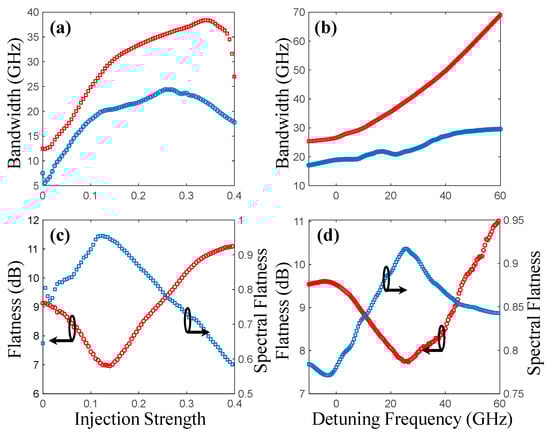
Figure 4.
Chaos properties of a cascaded optically injected laser at a fixed detuning frequency of f2 = 16 GHz as a function of the injection strength (left column) and at a fixed injection strength of ξ2 = 0.2 as a function of the detuning frequency (right column). (a,b) standard bandwidth (red squares) and effective bandwidth (blue circles), (c,d) flatness (red circles) and spectral flatness (blue squares) of the chaotic output spectrum.
Figure 4a shows that as the injection strength is varied both the SBW (red squares) and the EBW (blue circles) reach a maximum value and then saturate as the injection strength is further increased. The generated chaotic spectrum shows prominent peaks at frequency components that are a result of nonlinear frequency mixing between the relaxation resonance of SL1, the detuning frequency, and the optical injection-enhanced relaxation resonance peak of SL2, as shown in Figure 3. As the injection strength is increased, these prominent peaks spread further apart and become weaker than the peak at the relaxation resonance frequency of SL1 resulting in reduced SBW and EBW. Figure 4b shows that as the detuning frequency is increased the SBW (red squares) keeps increasing, however, the EBW (blue squares) saturate at high detuning frequencies. As the detuning frequency f2 is increased, the prominent peaks in the chaotic spectrum spread further apart, however, they do not become weaker as compared to the relaxation resonance frequency peak of SL1. Therefore, enhanced SBW and EBW are observed when the detuning frequency of the second stage is increased. The saturation effect of EBW, as the detuning frequency is increased, is a result of the wide region of low magnitude spectral components between the relaxation resonance frequency peak of SL1 and the other prominent spectral components, as illustrated in Figure 3d-ii. Figure 4c shows that as the injection strength is varied both the flatness (red circles) and the SF (blue squares) of the chaotic output spectrum reach extremum values and then saturate as the injection strength is further increased. Similarly, Figure 4d shows that as the detuning frequency is varied both the flatness (red circles) and the SF (blue squares) of the chaotic output spectrum reach extremum values then saturate as the detuning frequency is further increased. Clearly, both flatness and spectral flatness of the chaotic output spectrum show a similar trend and can be interchangeably used to quantify the smoothness of the chaotic spectrum. The smoothest chaotic output of SL2 is found at moderate injection strengths and detuning frequencies, as illustrated in Figure 3c-ii. The flat chaotic output of SL2 at these operating points is due to the proximity of the prominent spectral peaks of the cascaded optically injected laser.
To further demonstrate the effects of the operational parameters on the chaotic properties, mapping of the chaotic properties of a cascaded optically injected semiconductor laser as a function of the injection strength and the detuning frequency are illustrated in Figure 5. The injection of chaotic light generated from the first optical injection stage is fixed at (ξ1, f1) = (0.05, 6.25 GHz) and renders the output of the second optical injection stage chaotic for all operational parameters (ξ2, f2). Figure 5a shows contour curves at increments of 5 GHz representing the SBW of chaos generated by a cascaded optically injected laser. The maximum carrier frequency of the chaotic output represented by the SBW is observed at high detuning frequencies and strong injection strengths. At low detuning frequencies, small SBW are observed due to synchronized SL2 and SL1 output due to locking. Figure 5b shows contour curves at increments of 5 GHz representing the EBW of chaos generated by a cascaded optically injected laser. The EBW distinguishes chaotic dynamics from other narrowband dynamics through the EBW value. The output of the cascaded optically injected laser is chaotic for all operating parameters, as demonstrated by the broad EBW of the generated dynamics of Figure 5b. Similar to the SBW map, narrow EBW is observed at strong injection strengths and low detuning frequencies due to synchronized SL2 and SL1 outputs owing to strong injection locking. On the other hand, the broadest EBW of chaos is observed at weak injection strength and high detuning frequencies, as illustrated in Figure 3b-ii. Increasing the injection strength results in the spreading of the prominent peaks of the chaotic output which creates a wide range of low-magnitude spectral components between the relaxation resonance frequency peak of SL1 and the other prominent spectral components, as illustrated in Figure 3d-ii. Figure 5c and Figure 5d show contour curves representing the SF at increments of 0.05 and flatness at increments of 1 dB of the chaotic output spectrum generated by a cascaded optically injected laser, respectively. Both Figure 5c,d show a similar trend of the flatness of the chaotic spectrum of the cascaded optically injected laser. The flattest chaotic output of SL2 is found at moderate injection strengths and detuning frequencies resulting in a chaotic output spectrum as illustrated in Figure 3c-ii. The flat chaotic output of SL2 at this operating region is due to the proximity of the prominent peaks of the cascaded optically injected laser.
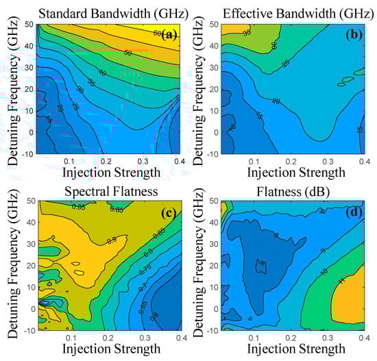
Figure 5.
Mapping of the chaotic properties of a cascaded optically injected semiconductor laser as a function of the injection strength and the detuning frequency. (a) standard bandwidth, (b) effective bandwidth, (c) flatness, and (d) spectral flatness.
5. Conclusions
In conclusion, experiments and numerical calculations have been conducted to generate flat broadband chaos using a semiconductor laser under cascaded optical injection. The chaotic output generated by continuous-wave optical injection is used to optically inject a third semiconductor laser to enhance the chaotic properties. Unlike chaos generated by delay-based configurations, the chaos generated by a cascaded optically injected semiconductor laser inherently does not show any time-delay signatures. This approach allows for enhancement in the bandwidth and spectral flatness without the limitations imposed by the need for simultaneous optimized operation for TDS suppression. Furthermore, chaos generated by the second optical injection shows no loss of chaotic dynamics as the operating conditions are continuously varied in the parameter space. The chaotic power spectrum generated by a cascaded optically injected semiconductor laser shows prominent peaks around the relaxation resonance of SL1, the detuning frequency, the optical injection-enhanced relaxation resonance peak of SL2, and frequency components that result from the nonlinear frequency mixing of these spectral components. Through the proper choice of the operating parameters of the second stage, the peak structure associated with chaos generated by optical injection is flattened. The relaxation resonance peak in the chaotic dynamics can be flattened through nonlinear frequency mixing between the other prominent peaks of the chaotic dynamics reaching spectral flatness of SF > 0.9. Chaotic dynamics with a standard and effective bandwidth up to six and three times the relaxation resonance frequency is achieved. Simultaneous flat and broadband chaos is observed at weak injection strengths and high detuning frequencies. Furthermore, the work presented here complements ongoing efforts to produce broadband chaotic oscillations with flat spectra and suppressed TDS. The mappings of the chaotic properties of a cascaded optically injected laser can be used as a guide even when chaos is generated by other mechanisms in the first stage. Note that the comparison should be made while scaling the detuning frequency in the generated maps to the relaxation resonance frequency of SL1 and SL2. The favorable features of chaos generated by cascaded optical injection can be further enhanced by adding another stage of optical injection. Therefore, the cascaded optical injection approach for chaos generation without any feedback loops is a potential candidate for low-dimensional chaotic applications.
Funding
This work was supported and funded by Kuwait University Research Grant No. EE02/24.
Institutional Review Board Statement
Not applicable.
Informed Consent Statement
Not applicable.
Data Availability Statement
Data presented in this study are available upon request from the corresponding author.
Conflicts of Interest
The author declares no conflicts of interest.
References
- Ohtsubo, J. Semiconductor Lasers: Stability, Instability and Chaos; Springer: Berlin/Heidelberg, Germany, 2012; Volume 111. [Google Scholar]
- Sciamanna, M.; Shore, K.A. Physics and applications of laser diode chaos. Nat. Photonics 2015, 9, 151–162. [Google Scholar] [CrossRef]
- Ye, J.; Gao, X.; Li, X.; Yang, H.; An, Y.; Xu, P.; Wang, A.; Dong, X.; Wang, Y.; Qin, Y.; et al. Physical layer security-enhanced optical communication based on chaos masking and chaotic hardware encryption. Opt. Express 2024, 32, 27734–27747. [Google Scholar] [CrossRef] [PubMed]
- Xue, C.; Zheng, L.; Wang, X.; Zhu, B.; Zhang, Z.; Hong, Y. High-speed secure stream cipher using synchronized chaos and the RC4 algorithm for optical communications. Opt. Express 2025, 33, 488–500. [Google Scholar] [CrossRef]
- Tseng, C.-H.; Funabashi, R.; Kanno, K.; Uchida, A.; Wei, C.-C.; Hwang, S.-K. Entropy analysis on chaos excited through destabilization of semiconductor lasers at period-one nonlinear dynamics for physical random number generation. Opt. Express 2024, 32, 23097–23114. [Google Scholar] [CrossRef] [PubMed]
- Lin, F.Y.; Liu, J.M. Chaotic lidar. IEEE J. Sel. Top. Quantum Electron. 2004, 10, 991–997. [Google Scholar] [CrossRef]
- Xiong, W.; Bai, Q.; Hu, Y.; Zhang, X.; Wu, Y.; Xia, G.; Zhou, H.; Wu, J.; Wu, Z. 3D parallel pulsed chaos LiDAR system. Opt. Express 2024, 32, 11763–11773. [Google Scholar] [CrossRef]
- Yang, B.; Sun, J.; Chi, H.; Xu, K.; Yang, S. Joint radar and communication system based on a chaotic optoelectronic oscillator. Opt. Commun. 2024, 554, 130123. [Google Scholar] [CrossRef]
- Lin, F.Y.; Liu, J.M. Chaotic radar using nonlinear laser dynamics. IEEE J. Quantum Electron. 2004, 40, 815–820. [Google Scholar] [CrossRef]
- Dong, X.; Wang, A.; Zhang, J.; Han, H.; Zhao, T.; Liu, X.; Wang, Y. Combined attenuation and high-resolution fault measurements using chaos-OTDR. IEEE Photon. J. 2015, 7, 6804006. [Google Scholar]
- Li, X.-Z.; Yang, B.; Zhao, S.; Gu, Y.; Zhao, M. On prediction of chaotic dynamics in semiconductor lasers by reservoir computing. Opt. Express 2023, 31, 40592–40603. [Google Scholar] [CrossRef]
- Brückerhoff-Plückelmann, F.; Borras, H.; Klein, B.; Varri, A.; Becker, M.; Dijkstra, J.; Brückerhoff, M.; Wright, C.D.; Salinga, M.; Bhaskaran, H. Probabilistic photonic computing with chaotic light. Nat. Commun. 2024, 15, 10445. [Google Scholar] [CrossRef] [PubMed]
- Hemery, E.; Chusseau, L.; Lourtioz, J.M. Dynamic behaviors of semiconductor lasers under strong sinusoidal current modulation: Modeling and experiments at 1.3 um. IEEE J. Quantum Electron. 1990, 26, 633–641. [Google Scholar] [CrossRef]
- Liu, H.F.; Ngai, W.F. Nonlinear dynamics of a directly modulated 1.55um InGaAsP distributed feedback semiconductor laser. IEEE J. Quantum Electron. 1993, 29, 1668–1675. [Google Scholar] [CrossRef]
- Vicente, R.; Daudén, J.; Colet, P.; Toral, R. Analysis and characterization of the hyperchaos generated by a semiconductor laser subject to a delayed feedback loop. IEEE J. Quantum Electron. 2005, 41, 541–548. [Google Scholar] [CrossRef]
- Tang, S.; Liu, J.M. Chaotic pulsing and quasi-periodic route to chaos in a semiconductor laser with delayed opto-electronic feedback. IEEE J. Quantum Electron. 2001, 37, 329–336. [Google Scholar] [CrossRef]
- Simpson, T.B.; Liu, J.M.; Huang, K.F.; Tai, K. Nonlinear dynamics induced by external optical injection in semiconductor lasers. J. Opt. B Quantum Semiclassical Opt. 1997, 9, 765. [Google Scholar] [CrossRef]
- Uchida, A.; Heil, T.; Liu, Y.; Davis, P.; Aida, T. High-Frequency Broad-Band Signal Generation Using a Semiconductor Laser with a Chaotic Optical Injection. IEEE J. Quantum Electron. 2003, 39, 1462–1467. [Google Scholar] [CrossRef]
- Lin, F.Y.; Liu, J.M. Nonlinear dynamical characteristics of an optically injected semiconductor laser subject to optoelectronic feedback. Opt. Commun. 2003, 221, 173–180. [Google Scholar] [CrossRef]
- Tang, S.; Vicente, R.; Chiang, M.C.; Mirasso, C.R.; Liu, J.M. Nonlinear dynamics of semiconductor lasers with mutual optoelectronic coupling. IEEE J. Sel. Top. Quantum Electron. 2004, 10, 936–943. [Google Scholar] [CrossRef]
- Al-Hosiny, N.M.; Henning, I.D.; Adams, M.J. Tailoring enhanced chaos in optically injected semiconductor lasers. Opt. Commun. 2007, 269, 166–173. [Google Scholar] [CrossRef]
- Someya, H.; Oowada, I.; Okumura, H.; Kida, T.; Uchida, A. Synchronization of bandwidth-enhanced chaos in semiconductor lasers with optical feedback and injection. Opt. Express 2009, 17, 19536–19543. [Google Scholar] [PubMed]
- AlMulla, M. Period-doubling route to chaos in perturbed period-one nonlinear dynamics. Results Phys. 2025, 70, 108164. [Google Scholar] [CrossRef]
- Sakuraba, R.; Iwakawa, K.; Kanno, K.; Uchida, A. Tb/s physical random bit generation with bandwidth-enhanced chaos in three-cascaded semiconductor lasers. Opt. Express 2015, 23, 1470–1490. [Google Scholar] [CrossRef] [PubMed]
- Wang, Y.; Jia, Z.; Gao, Z.; Xiao, J.; Wang, L.; Wang, Y.; Huang, Y.; Wang, A. Generation of laser chaos with wide-band flat power spectrum in a circular-side hexagonal resonator microlaser with optical feedback. Opt. Express 2020, 28, 18507–18515. [Google Scholar] [CrossRef]
- Rontani, D.; Locquet, A.; Sciamanna, M.; Citrin, D.S.; Ortin, S. Time-Delay Identification in a Chaotic Semiconductor Laser with Optical Feedback: A Dynamical Point of View. IEEE J. Quantum Electron. 2009, 45, 879–1891. [Google Scholar] [CrossRef]
- Zunino, L.; Rosso, O.A.; Soriano, M.C. Characterizing the hyperchaotic dynamics of a semiconductor laser subject to optical feedback via permutation entropy. IEEE J. Sel. Top. Quantum Electron. 2011, 17, 1250–1257. [Google Scholar] [CrossRef]
- Takiguchi, Y.; Ohyagi, K.; Ohtsubo, J. Bandwidth-enhanced chaos synchronization in strongly injection-locked semiconductor lasers with optical feedback. Opt. Lett. 2003, 28, 319–321. [Google Scholar] [CrossRef]
- Gao, X.; Zhu, W.; Yang, Q.; Zeng, D.; Deng, L.; Chen, Q.; Cheng, M. Time delay estimation from the time series for optical chaos systems using deep learning. Opt. Express 2021, 29, 7904–7915. [Google Scholar] [CrossRef]
- Wang, A.-B.; Wang, Y.-C.; Wang, J.-F. Route to broadband chaos in a chaotic laser diode subject to optical injection. Opt. Lett. 2009, 34, 1144–1146. [Google Scholar] [CrossRef]
- Li, N.; Pan, W.; Locquet, A.; Citrin, D.S. Time-delay concealment and complexity enhancement of an external-cavity laser through optical injection. Opt. Lett. 2015, 40, 4416–4419. [Google Scholar] [CrossRef]
- Chan, S.-C.; Tang, W.K.S. Chaotic Dynamics of Laser Diodes with Strongly Modulated Optical Injection. Int. J. Bifurc. Chaos 2009, 19, 3417–3424. [Google Scholar] [CrossRef]
- Hong, Y.; Spencer, P.S.; Shore, K.A. Flat Broadband Chaos in Vertical-Cavity Surface-Emitting Lasers Subject to Chaotic Optical Injection. IEEE J. Quantum Electron. 2012, 48, 1536–1541. [Google Scholar] [CrossRef]
- Rontani, D.; Locquet, A.; Sciamanna, M.; Citrin, D.S. Loss of time-delay signature in the chaotic output of a semiconductor laser with optical feedback. Opt. Lett. 2007, 32, 2960–2962. [Google Scholar] [CrossRef] [PubMed]
- Kanno, K.; Uchida, A.; Bunsen, M. Complexity and bandwidth enhancement in unidirectionally coupled semiconductor lasers with time-delayed optical feedback. Phys. Rev. E 2016, 93, 032206. [Google Scholar] [CrossRef]
- Zhang, M.; Liu, T.; Li, P.; Wang, A.; Zhang, J.; Wang, Y. Generation of Broadband Chaotic Laser Using Dual-Wavelength Optically Injected Fabry–Pérot Laser Diode with Optical Feedback. IEEE Photonics Technol. Lett. 2011, 23, 1872–1874. [Google Scholar] [CrossRef]
- AlMulla, M.; Qi, X.Q.; Liu, J.M. Dynamics Maps and Scenario Transitions for a Semiconductor Laser Subject to Dual-Beam Optical Injection. IEEE J. Sel. Top. Quantum Electron. 2013, 19, 1501108. [Google Scholar] [CrossRef]
- Hirano, K.; Yamazaki, T.; Morikatsu, S.; Okumura, H.; Aida, H.; Uchida, A.; Yoshimori, S.; Yoshimura, K.; Harayama, T.; Davis, P. Fast random bit generation with bandwidth-enhanced chaos in semiconductor lasers. Opt. Express 2010, 18, 5512–5524. [Google Scholar] [CrossRef]
- Chen, J.; Duan, Y.; Li, L.; Zhong, Z. Wideband Polarization-Resolved Chaos with Time-Delay Signature Suppression in VCSELs Subject to Dual Chaotic Optical Injections. IEEE Access 2018, 6, 66807–66815. [Google Scholar] [CrossRef]
- Xiang, S.Y.; Pan, W.; Li, N.Q.; Luo, B.; Yan, L.S.; Zou, X.H.; Zhang, L.; Mu, P. Randomness-Enhanced Chaotic Source with Dual-Path Injection From a Single Master Laser. IEEE Photonics Technol. Lett. 2012, 24, 1753–1756. [Google Scholar] [CrossRef]
- Li, N.; Pan, W.; Xiang, S.; Yan, L.; Luo, B.; Zou, X. Loss of Time Delay Signature in Broadband Cascade-Coupled Semiconductor Lasers. IEEE Photonics Technol. Lett. 2012, 24, 2187–2190. [Google Scholar] [CrossRef]
- Li, S.-S.; Chan, S.-C. Chaotic Time-delay Signature Suppression in a Semiconductor Laser with Frequency-detuned Grating Feedback. IEEE J. Sel. Top. Quantum Electron. 2015, 21, 541–552. [Google Scholar] [CrossRef]
- Rontani, D.; Mercier, E.; Wolfersberger, D.; Sciamanna, M. Enhanced complexity of optical chaos in a laser diode with phase-conjugate feedback. Opt. Lett. 2016, 41, 4637–4640. [Google Scholar] [CrossRef] [PubMed]
- Hong, Y. Experimental study of time-delay signature of chaos in mutually coupled vertical-cavity surface-emitting lasers subject to polarization optical injection. Opt. Express 2013, 21, 17894–17903. [Google Scholar] [CrossRef] [PubMed]
- Han, Y.; Xiang, S.; Wang, Y.; Ma, Y.; Wang, B.; Wen, A.; Hao, Y. Generation of multi-channel chaotic signals with time delay signature concealment and ultrafast photonic decision making based on a globally-coupled semiconductor laser network. Photon. Res. 2020, 8, 1792–1799. [Google Scholar] [CrossRef]
- Guo, X.X.; Xiang, S.Y.; Zhang, Y.H.; Wen, A.J.; Hao, Y. Information-theory-based complexity quantifier for chaotic semiconductor laser with double time delays. IEEE J. Quantum Electron. 2018, 54, 2000308. [Google Scholar]
- Xiang, S.; Pan, W.; Zhang, L.; Wen, A.; Shang, L.; Zhang, H.; Lin, L. Phase-modulated dual-path feedback for time delay signature suppression from intensity and phase chaos in semiconductor laser. Opt. Commun. 2014, 324, 38–46. [Google Scholar] [CrossRef]
- Zhao, A.; Jiang, N.; Liu, S.; Xue, C.; Tang, J.; Qiu, K. Wideband complex-enhanced chaos generation using a semiconductor laser subject to delay-interfered self-phase-modulated feedback. Opt. Express 2019, 27, 12336–12348. [Google Scholar] [CrossRef]
- Han, H.; Cheng, X.M.; Jia, Z.W.; Shore, K.A. Suppression of Cavity Time-Delay Signature Using Noise-Phase-Modulated Feedback. IEEE Access 2020, 8, 35344–35349. [Google Scholar] [CrossRef]
- Cheng, C.-H.; Chen, Y.-C.; Lin, F.-Y. Chaos time delay signature suppression and bandwidth enhancement by electrical heterodyning. Opt. Express 2015, 23, 2308–2319. [Google Scholar] [CrossRef]
- Wang, A.; Yang, Y.; Wang, B.; Zhang, B.; Li, L.; Wang, Y. Generation of wideband chaos with suppressed time-delay signature by delayed self-interference. Opt. Express 2013, 21, 8701–8710. [Google Scholar] [CrossRef]
- Wang, A.; Wang, Y.; Yang, Y.; Zhang, M.; Xu, H.; Wang, B. Generation of flat-spectrum wideband chaos by fiber ring resonator. Appl. Phys. Lett. 2013, 102, 031112. [Google Scholar] [CrossRef]
- Qu, Y.; Xiang, S.; Wang, Y.; Lin, L.; Wen, A.J.; Hao, Y. Concealment of time delay signature of chaotic semiconductor nanolasers with double chaotic optical injections. IEEE J. Quantum Electron. 2019, 55, 2000407. [Google Scholar]
- Elsonbaty, A.; Hegazy, S.F.; Obayya, S.S.A. Simultaneous concealment of time delay signature in chaotic nanolaser with hybrid feedback. Opt. Lasers Eng. 2018, 107, 342–351. [Google Scholar] [CrossRef]
- Hong, Y.; Quirce, A.; Wang, B.; Ji, S.; Panajotov, K.; Spencer, P.S. Concealment of Chaos Time-Delay Signature in Three-Cascaded Vertical-Cavity Surface-Emitting Lasers. IEEE J. Quantum Electron. 2016, 52, 2400508. [Google Scholar] [CrossRef]
- Chang, D.; Zhong, Z.; Tang, J.; Spencer, P.S.; Hong, Y. Flat broadband chaos generation in a discrete-mode laser subject to optical feedback. Opt. Express 2020, 28, 39076–39083. [Google Scholar]
- Zeng, Y.; Zhou, P.; Huang, Y.; Mu, P.; Li, N. Wideband and high-dimensional chaos generation using optically pumped spin-VCSELs. Opt. Express 2023, 31, 948–963. [Google Scholar]
- Zhang, X.; Guo, G.; Liu, X.; Hu, G.; Wang, K.; Mu, P. Dynamics and Concealment of Time-Delay Signature in Mutually Coupled Nano-Laser Chaotic Systems. Photonics 2023, 10, 1196. [Google Scholar] [CrossRef]
- Ruan, J.; Chan, S.C. Simultaneous Coherent Detection with Baseband Enhancement in Chaotic Random Bit Generation by an Optically Injected Laser. IEEE J. Quantum Electron. 2023, 59, 1400108. [Google Scholar] [CrossRef]
- Kawaguchi, Y.; Okuma, T.; Kanno, K.; Uchida, A. Entropy rate of chaos in an optically injected semiconductor laser for physical random number generation. Opt. Express 2021, 29, 2442–2457. [Google Scholar] [CrossRef]
- Li, X.; Li, S.; Chan, S. Correlated Random Bit Generation Using Chaotic Semiconductor Lasers Under Unidirectional Optical Injection. IEEE Photon. J. 2017, 9, 1505411. [Google Scholar] [CrossRef]
- Tseng, C.-H.; Funabashi, R.; Kanno, K.; Uchida, A.; Wei, C.-C.; Hwang, S.-K. High-entropy chaos generation using semiconductor lasers subject to intensity-modulated optical injection for certified physical random number generation. Opt. Lett. 2021, 46, 3384–3387. [Google Scholar] [CrossRef] [PubMed]
- Tseng, C.-H.; Hwang, S.-K. Broadband chaotic microwave generation through destabilization of period-one nonlinear dynamics in semiconductor lasers for radar applications. Opt. Lett. 2020, 45, 3777–3780. [Google Scholar] [CrossRef] [PubMed]
- Doumbia, Y.; Malica, T.; Wolfersberger, D.; Sciamanna, M. Wideband chaos induced by the optical injection of a frequency comb. Opt. Lett. 2023, 48, 1442–1445. [Google Scholar] [PubMed]
- Nguimdo, R.M.; Soriano, M.C.; Colet, P. Role of the phase in the identification of delay time in semiconductor lasers with optical feedback. Opt. Lett. 2011, 36, 4332–4334. [Google Scholar]
- Li, N.; Pan, W.; Xiang, S.; Yan, L.; Luo, B.; Zou, X.; Zhang, L.; Mu, P. Photonic generation of wideband time-delay-signature-eliminated chaotic signals utilizing an optically injected semiconductor laser. IEEE J. Quantum Electron. 2012, 48, 1339–1345. [Google Scholar]
- AlMulla, M.; Liu, J.M. Linewidth characteristics of period-one dynamics induced by optically injected semiconductor lasers. Opt. Express 2020, 28, 14677–14693. [Google Scholar] [CrossRef]
- Hwang, S.K.; Liu, J.M.; White, J.K. 35-GHz Intrinsic Bandwidth for Direct Modulation in 1.3-um Semiconductor Lasers Subject to Strong Injection Locking. IEEE Photonics Technol. Lett. 2004, 16, 972–974. [Google Scholar]
- Lin, F.Y.; Chao, Y.K.; Wu, T.-C. Effective Bandwidths of Broadband Chaotic Signals. IEEE J. Quantum Electron. 2012, 48, 1010–1014. [Google Scholar] [CrossRef]
- Bandt, C.; Pompe, B. Permutation entropy: A natural complexity measure for time series. Phys. Rev. Lett. 2002, 88, 174102. [Google Scholar]
- AlMulla, M. Optimizing optically injected semiconductor lasers for periodic dynamics with reduced sensitivity to perturbations. Opt. Express 2019, 27, 17283–17297. [Google Scholar] [CrossRef]
- AlMulla, M.; Liu, J.M. Effects of the Gain Saturation Factor on the Nonlinear Dynamics of Optically Injected Semiconductor Lasers. IEEE J. Quantum Electron. 2014, 50, 158–165. [Google Scholar] [CrossRef]
Disclaimer/Publisher’s Note: The statements, opinions and data contained in all publications are solely those of the individual author(s) and contributor(s) and not of MDPI and/or the editor(s). MDPI and/or the editor(s) disclaim responsibility for any injury to people or property resulting from any ideas, methods, instructions or products referred to in the content. |
© 2025 by the author. Licensee MDPI, Basel, Switzerland. This article is an open access article distributed under the terms and conditions of the Creative Commons Attribution (CC BY) license (https://creativecommons.org/licenses/by/4.0/).