Article

Hybrid Growth of Clad Crystalline Sapphire Fibers for Ultra-High-Temperature (>1500 °C) Fiber Optic Sensors

1
Department of Electrical Engineering, The Pennsylvania State University, University Park, PA 16802, USA
2
General Opto Solutions, LLC, State College, PA 16803, USA
*
Author to whom correspondence should be addressed.
Photonics 2025, 12(4), 299; https://doi.org/10.3390/photonics12040299
Submission received: 7 January 2025 / Revised: 11 March 2025 / Accepted: 20 March 2025 / Published: 25 March 2025

Abstract

:
Ultra-high-temperature (>1500 °C) sensors play vital roles in ensuring operational excellence in variety of energy-related applications, such as power plant boilers and gas turbine engines. Crystalline sapphire fibers have enormous potential to replace conventional expensive precious metal (e.g., Pt/Rh)-based high-temperature (>1500 °C) sensors by offering higher environmental robustness and distributed sensing capabilities. However, a lack of proper cladding substantially compromises the performance of the sensor. To overcome this fundamental limitation, we develop a hybrid growing method to fabricate low-loss clad crystalline sapphire fibers. We grow a higher-refractive-index doped crystalline sapphire fiber core using the laser-heated pedestal growth (LHPG) method and lower-refractive-index undoped crystalline sapphire fiber cladding using the liquid-phase epitaxy (LPE) method. Furthermore, due to the existence of this cladding layer, a single mode of operation can be achieved at a core diameter size of 30 μm. The experimental results confirm that the grown clad crystalline sapphire fiber can survive in extremely high-temperature (>1500 °C) harsh environments due to the matched coefficient of thermal expansion (CTE) between the fiber core and the cladding. The numerical results also indicate a temperature sensing accuracy of 3.5 °C. This opens the door for developing point and distributed fiber sensor networks capable of enduring extremely harsh environments at extremely high temperatures.

1. Introduction

There is a growing demand for ultra-high-temperature (>1500 °C) sensors to ensure efficient operation in the aviation, smelting, and power industries, because temperature is one of the most important parameters used to monitor the safety status and to estimate the performance deterioration of these systems [1,2]. Researchers have developed diverse types of high-temperature sensors over the years. The most commercially available high-temperature sensors are (1) thermocouples [3], (2) temperature-sensing paints [4,5], and (3) infrared thermal images. Unfortunately, all of these conventional high-temperature sensors suffer certain limitations. For example, thermocouples are susceptible to electromagnetic interference and pose difficulty in achieving distributed sensing [3]. Furthermore, the use of precious metals (such as platinum and rhodium) makes ultra-high-temperature (>1500 °C) thermocouples expensive. Moreover, we can use temperature-sensing paints and infrared thermal images for surface temperature measurement only.
To overcome the limitations of conventional high-temperature sensors mentioned above, researchers have recently explored fiber optic sensors for high-temperature sensing applications [6], which have the advantages of being immune to electromagnetic interference because of the dielectric nature of optical fibers and their distributed sensing capability. Therefore, researchers can readily obtain the temperature distribution along the fiber. Silica glass-based fiber optic sensors have been successful in measuring temperature and temperature distributions up to 1000 °C. However, they are not suitable for ultra-high-temperature (>1500 °C) applications because their mechanical properties, such as the mechanical strength of silica glass fibers, start to deteriorate when the operational temperature is higher than 1000 °C due to the crystallization of silica glass material at high temperatures (>1000 °C) [6].
On the other hand, single-crystalline sapphire fiber is suitable for ultra-high-temperature (>1500 °C) sensing because sapphire has a high melting temperature (2045 °C) and mechanical strength [7]. Researchers have recently developed diverse types of sapphire-fiber-based ultra-high-temperature (>1500 °C) sensors, including fiber Bragg grating (FBG)-based high-temperature sensors [8,9] and Fabry–Perot cavity-based high-temperature sensors [10]. Although sapphire fiber sensors have been successful in ultra-high-temperature (>1500 °C) sensing, they also suffer from certain limitations. One fundamental limitation is the lack of proper cladding. Without proper cladding, the sapphire fiber is highly multimode, which compromises the performance of the sapphire fiber sensor. For example, the reflection spectral width of a core-only sapphire FBG fiber sensor is usually very wide (e.g., >10 nm) [8,9], which limits the signal-to-noise ratio (SNR) of the detected spectral signal. Furthermore, the lack of proper cladding also makes it sensitive to environmental perturbations [11]. For example, the deposition of particles on the sapphire fiber surface from the high-temperature chamber (e.g., jet turbine exhaust gas) can change the effective refractive index of sapphire fiber, which in turn affects the light propagation in the optical fiber. Furthermore, the output speckle pattern (Specklegram) of multimode fiber is sensitive to environmental vibrations due to the change of phase differences among different propagation modes [6].
Clad single-mode sapphire fiber is crucial in achieving a high SNR and robust sensing at ultra-high temperatures (>1500 °C) due to the following reasons: First, the single-mode fiber offers a narrower reflection spectrum for the sapphire FBG fiber sensor, which can increase the SNR and the distributed sensing capability [6]. Second, the single-mode operation also provides a more stable signal because the light propagation in single-mode fiber is more robust against ambient perturbations, such as vibration, leading to a more robust sensing capability. Third, the cladding can also serve as a protection layer, which can mitigate the influence of ambient perturbations. For example, the light propagation in the fiber core is immune to the particles of jet engine exhaust gas due to the existence of the protection effect of the cladding layer. Unfortunately, unlike amorphous glass fiber, we cannot form clad crystalline sapphire fibers by simply pulling down from a vitreous melt. Therefore, we cannot readily fabricate crystalline fiber cladding in the same way as glass fiber cladding by simply pulling a glass core and a glass cladding preform.
To fabricate cladding on sapphire fiber cores, researchers have proposed and explored multiple methods [12,13,14], leading to certain progress. However, crystalline fibers with a high-transmittance sapphire fiber core and sapphire fiber cladding are still underdeveloped. For example, one method was to fabricate ceramic alumina cladding on a sapphire fiber core by high-temperature sintering [12]. This method successfully achieved a core/cladding architecture. However, there were considerable cracks due to the thermal stress formed during the extremely high-temperature (>1650 °C) sintering process, which limited the transmittance and the mechanical strength of the fabricated clad sapphire fiber. Another method was to fabricate spinel cladding on a sapphire fiber core via the reaction between magnesium oxide and the sapphire fiber core [13]. Again, this method successfully fabricated a core/cladding architecture. However, when the spinel cladding layer exceeds a certain thickness (e.g., > 50   μ m ), cracks can form due to the thermal stress caused by the coefficient of thermal expansion (CTE) mismatch between the sapphire fiber core and the spinel cladding at high operational temperatures (e.g., >1250 °C). This compromises its performance at ultra-high (>1500 °C) temperatures. The third example was to create a low-refractive-index area around the central region within the sapphire fiber via femtosecond laser illumination, resulting in a core/clad structure [14]. This method also used a single-mode sapphire fiber. However, due to the existence of scattering in the boundary between the low-refractive-index area created by the femtosecond laser illumination and the area without the femtosecond laser illumination, the background transmission loss figure is still about 1 dB/cm.
Recently, several other types of fiber optic sensors have been proposed and investigated. Although these fiber optic sensors have some advantages in some sensing applications, they cannot be readily used in ultra-high-temperature sensing in harsh environments. One type is based on liquid-filled photonic crystal fibers [15]. Although a high sensitivity can be achieved in this type of sensor, it is not suitable for ultra-high-temperature application because liquid cannot survive at elevated temperatures >1500 °C. Another type is the surface plasmon (SP)-based fiber optic sensor [16,17]. Although this type of sensor has good sensitivity and selectivity, it is not suitable for the high-temperature (>1500 °C) sensing in harsh environments. The metal layer can become molten and/or oxidized at >1500 °C in air. Another example is the fiber Bragg grating (FBG)-based sensor for robotic application [18]. This is a very interesting application. However, FBG inscribed in a conventional glass-based single-mode fiber cannot survive at elevated temperatures >1500 °C.
To realize less loss in clad sapphire fibers, we report an innovative method to fabricate a clad sapphire fiber based on a hybrid crystalline fiber growth approach [19] in this paper. We grow a higher-refractive-index crystalline doped sapphire fiber core using the laser-heated pedestal growth (LHPG) method and lower-refractive-index undoped crystalline sapphire fiber cladding using the liquid-phase epitaxy (LPE) method. The experimental results confirm that the grown clad crystalline sapphire fiber can survive in extremely harsh high-temperature (>1500 °C) environments due to the high-temperature survivability of the doped crystalline fiber core and the undoped pure crystalline fiber cladding, as well as the matched thermal expansion coefficient between the doped sapphire fiber core and the undoped sapphire fiber cladding. This opens the door for developing efficient ultra-high-temperature point and distributed fiber optic sensors.

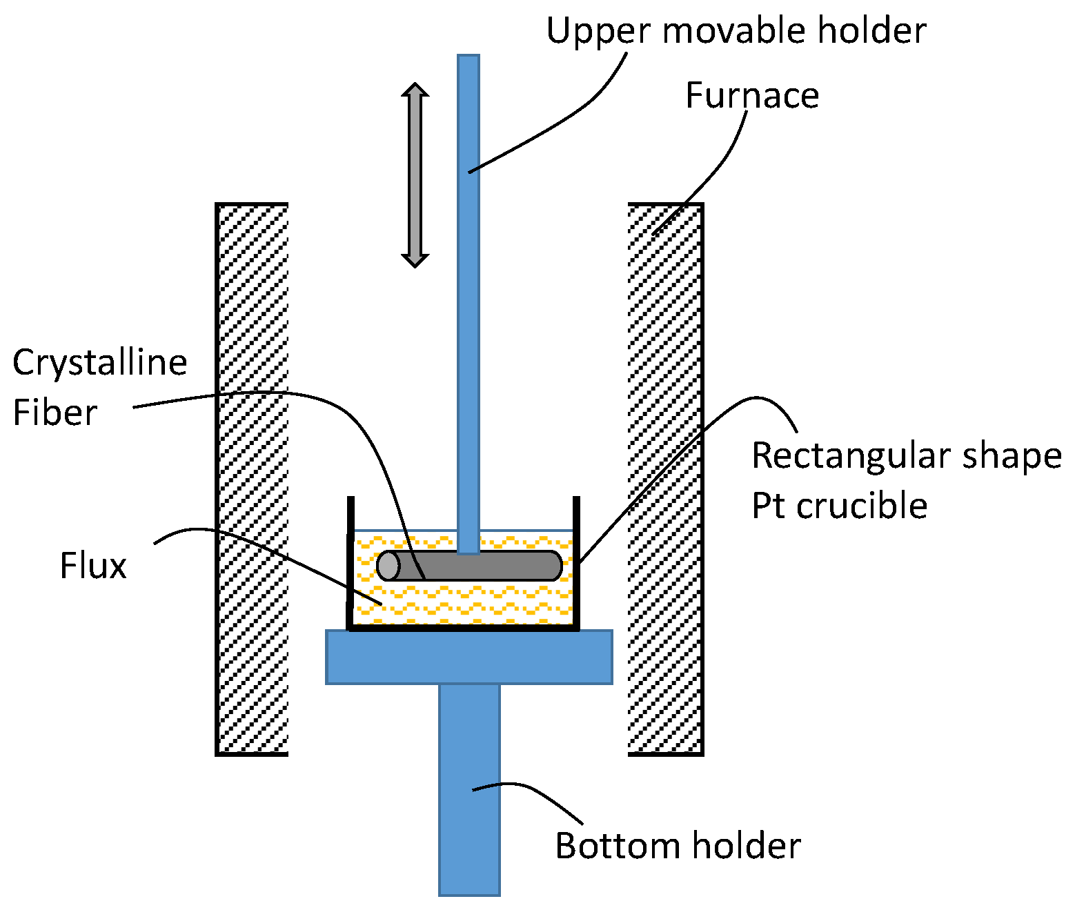
2. Materials and Methods

We used a hybrid growing method, recently developed by our team [19], to grow the clad crystalline sapphire fibers. This included two steps. The first step is to grow the single-crystalline fiber core by using the laser-heated pedestal growth (LHPG) method. Figure 1 illustrates the LHPG system used for drawing the fiber, which involves the following processes: (1) a donut-shaped CO2 laser beam is formed after passing through a reflaxicon and a reflection mirror; (2) the donut-shaped beam is focused on the tip of the feed rod preform made of a doped single-crystalline sapphire bar so that a molten zone is formed; (3) a pure sapphire seed rod is employed to contact the molten zone; and (4) the clad sapphire fiber is drawn by coordinately pulling the pure sapphire seed rod and the doped sapphire feed rod. In the experiment, a CO2 laser, made by Synrad (Mukilteo, WA, USA), with an output power of 50 W was used. The drawing speed was around 1 mm/min.
The second step is to grow pure sapphire crystalline cladding on the doped sapphire fiber core using the liquid-phase epitaxy (LPE) method, in which the doped single-crystalline fiber core serves as the seed for growing the single-crystalline cladding. Figure 2 illustrates the configuration of an advanced LPE growing system, recently developed by our team. The system is composed of (1) a heating furnace, (2) a Pt crucible, and (3) proper holding and drawing units. In the growing process, we immerse the doped single-crystalline sapphire seed core in a molten flux containing molten alumina powder to grow the crystalline cladding. The growing rate is around 1     μ m / hr .

3. Results

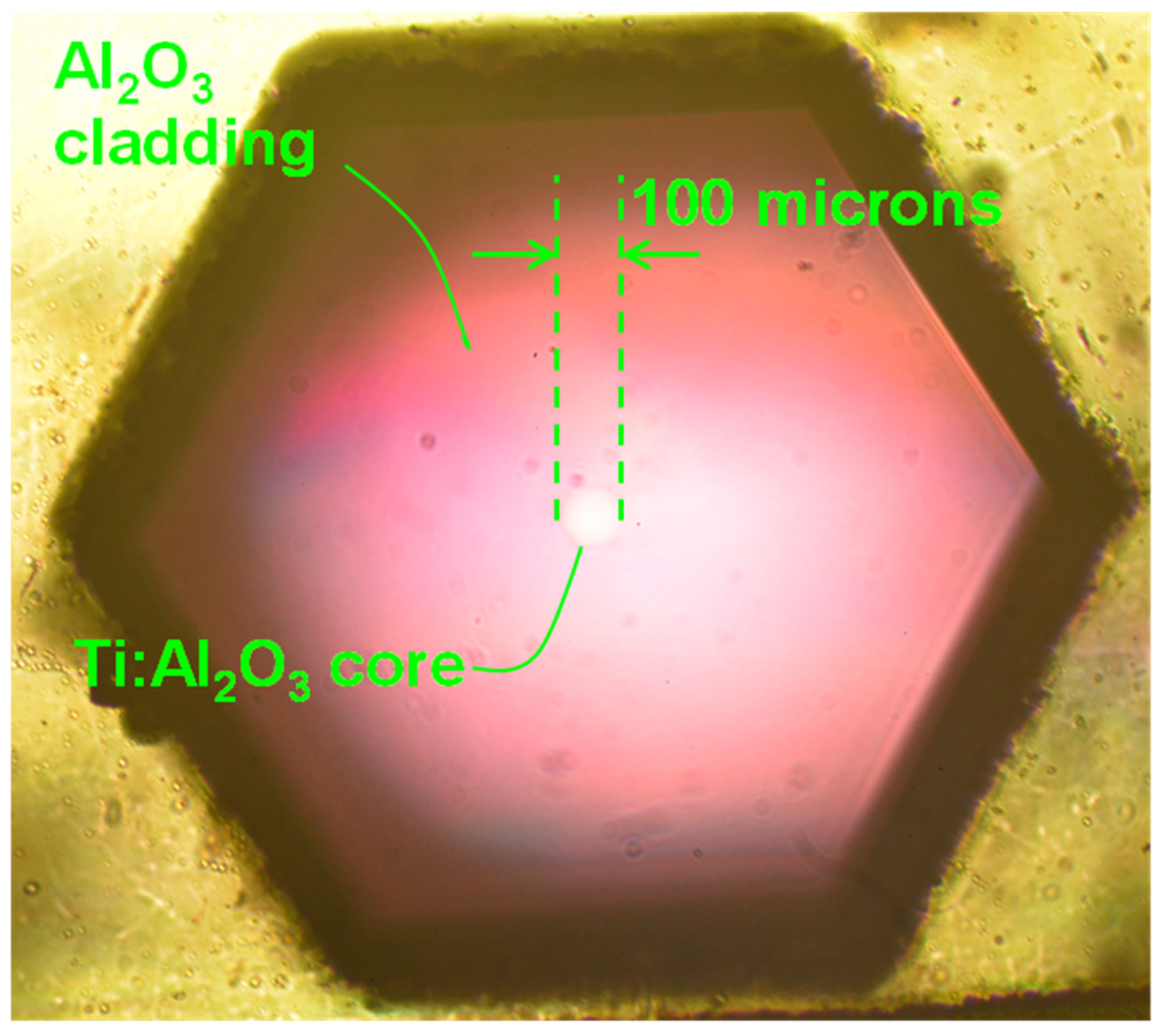
3.1. Graphic Illustration of a Grown Clad Crystalline Sapphire Fiber

Figure 3 shows the side view of a clad crystalline sapphire fiber grown using the hybrid growth method, as described in Section 2. It is composed of a titanium-doped single-crystalline sapphire fiber core (Ti: Al2O3) and pure single-crystalline sapphire fiber cladding (Al2O3), and marked as Ti: Al2O3/Al2O3 fiber. The length of the fiber is around 10 cm. The diameters of the Ti–sapphire core and pure sapphire cladding are around 100   μ m and 350   μ m , respectively.
Figure 4 shows the transmission end view through a Nikon MM60 (Tokyo, Japan) measuring microscope of another clad crystalline sapphire fiber grown using the hybrid growth method, as described in Section 2. It is composed of a titanium-doped single-crystalline sapphire fiber core (Ti: Al2O3) and pure single-crystalline sapphire fiber cladding (Al2O3). The diameters of the Ti–sapphire core and pure sapphire cladding are around 100   μ m and 1000   μ m , respectively. The fiber growth is along the C-axis. The refractive indices for the ordinary and extraordinary waves are around n o = 1.768 and n e = 1.760 , respectively, at the wavelength of 0.59   μ m . For this C-axis grown fiber, the guided light is an ordinary wave. From this transmission end view, one can clearly see the core and cladding structure. The brightness of the core is higher than that of the cladding region due to the light-guiding effect created by the higher refractive index of the Ti–sapphire fiber core. The cross-section of the cladding has a hexagonal shape, which is a typical shape of sapphire because it has a trigonal 3 m crystal symmetry. This also confirms that the grown cladding is a single-crystalline sapphire cladding. Furthermore, the pink color is due to the absorption of titanium ions (Ti3+).

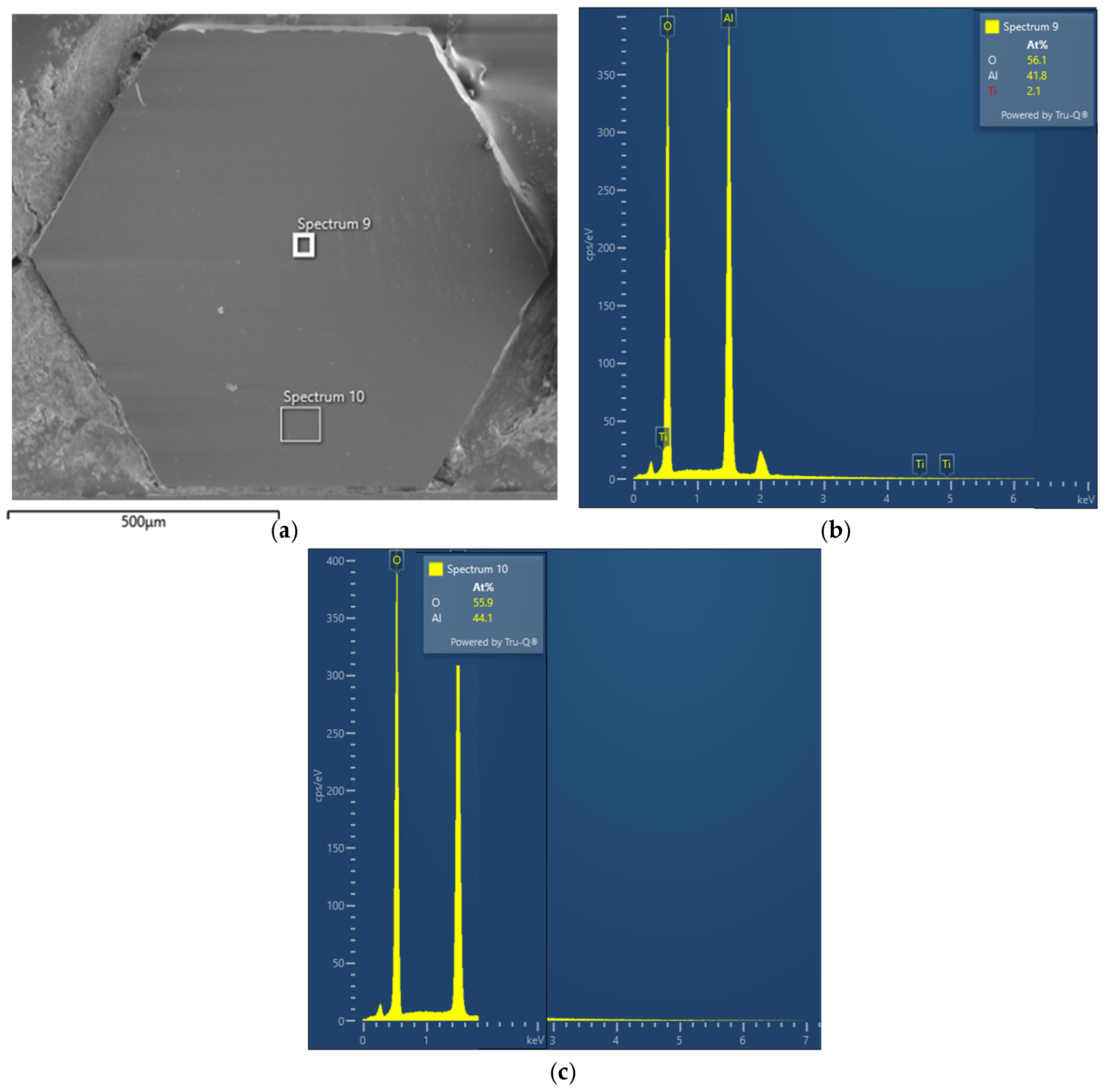
3.2. Characterizing the Composition of the Grown Clad Crystalline Sapphire Fiber

To ensure that the grown fiber was a clad crystalline sapphire fiber, we conducted composition analysis using a Thermo Verios G4 (Thermo Scientific, Waltham, MA, USA) scanning electron microscope with energy-dispersed spectroscopy (SEM/EDS). Figure 5a shows the corresponding scanning electron microscopic (SEM) image of the sample shown in Figure 4. Figure 5b shows the measured material composition of the core region, marked as the Spectrum 9 region. One can see that the core region contains Al, O, and Ti elements, which confirms that the core region is Ti: Al2O3. Figure 5c shows the measured material composition of the cladding region, marked as the Spectrum 10 region. One can see that the cladding region contains Al and O elements but no Ti element. This confirms that the cladding region is pure sapphire consisting of single-crystal Al2O3.

3.3. Confirmation of the Ultra-High-Temperature Sensing Capability of Grown Clad Crystalline Sapphire Fibers

To validate that the grown clad crystalline sapphire fibers were suitable for the high-temperature sensing application, we conducted the following experiment. First, we took a reflection microscopic picture of the end surface of a clad sapphire fiber sample, which had a cladding diameter of around 350   μ m , as shown in Figure 6a. Then, we put this fiber sample in a furnace and heated it up to an ultra-high temperature of 1600 °C for 10 h. After that, we took the sample out from the furnace and took a reflection microscopic picture of the same fiber, as shown in Figure 6b. One can see that there is no noticeable change. Thus, this experimental result confirms that we can use the clad sapphire fiber developed using our hybrid growth method for ultra-high-temperature sensing. Note that the high-temperature furnace accessible to us limited the achievable elevated temperature to 1600 °C. It is possible to operate at an even higher sensing temperature (1800–2000 °C) by harnessing this clad crystalline sapphire fiber.

3.4. Measurement of the Transmission Capacity of the Grown Clad Sapphire Fiber

We quantitatively measured the transmission capacity of the clad sapphire fiber. Figure 7a,b show a picture and a corresponding sketch of the experimental setup used to measure the transmission of the clad sapphire fiber, respectively. The experimental system was composed of (1) a red diode laser source with an output wavelength of 633 nm, (2) coupling lens 1, (3) a clad sapphire fiber embedded in a copper alloy u-channel, (4) coupling lens 2, and (5) a photodetector. The core and cladding diameters of the clad sapphire fiber were around 100   μ m and 500   μ m , respectively. The length of the clad sapphire fiber was around L = 2 cm. In the experiment, a red laser diode emitted a 633 nm laser beam, which was coupled into a clad sapphire fiber by coupling lens 1. The coupled laser beam propagated within the clad sapphire fiber and exited out from the output end of the fiber. The exited beam was then focused onto a photodetector by coupling lens 2. By measuring the input and output light intensities, the transmittance was determined. The measured input and output light intensities were I in = 89.7   μ W and I out = 88.6   μ W , respectively, from which light transmission was derived as η = I in / I out = 98.8 % . The corresponding background loss figure was α = 10 log ( η ) / L = 0.026   dB / cm , which was significantly (more than one order of magnitude) lower than that of previously reported data on clad sapphire fibers [14].

4. Discussion

4.1. Analysis of the Linearity of Clad Crystalline Sapphire Fiber at Elevated Temperature

To model the performance of the clad crystalline sapphire fiber at elevated temperature, we analyzed the linearity of the low-loss clad crystalline sapphire fiber at elevated temperatures (>1500 °C) from the following aspects: First, the mechanical and optical properties of the clad sapphire fiber should be akin to the case of bulk crystal, since both the fiber core and cladding were in the single-crystalline sapphire form. The usable mechanical strength and the optical transmission of the fiber limit the ultimate operating temperature, which can be as high as 2020 °C [20]. Second, the performance of the clad sapphire fiber was better than that of the core-only sapphire fiber at elevated temperatures (>1500 °C). The cladding can serve as a protection layer [11], which prevents the fiber core from the air oxidation effect at elevated temperatures [21]. Third, the sensing linearity of the clad crystalline sapphire fiber depends on the sensing mechanism. The following method can analyze the most popular sapphire FBG-based sensor. The Bragg resonant condition of FBG is as follows:
2 n e f f Λ = m λ B ,
where n e f f is the effective refractive index, Λ is the period of the FBG, m is the Bragg resonant order, and λ B is the Bragg resonant wavelength. The corresponding derived temperature sensitivity, d λ B / dT , is as follows:
d λ B dT = λ B 1 n e f f d n e f f dT + 1 Λ d Λ dT .
Since both the thermo-optic coefficient 1 n e f f d n e f f dT and the thermal expansion coefficient 1 Λ d Λ dT of the sapphire crystal increase near linearly as temperature increases [22], the corresponding temperature sensitivity d λ B / dT also increases near linearly as temperature increases, in particular at elevated temperatures (>1500 °C). In other words, the Bragg resonant wavelength, λ B , is a near-parabolic function of temperature, T.

4.2. Modelling the Accuracy of the Temperature Measurements

To analyze the accuracy of the temperature measurement for the proposed fibers, we assume that the sensing mechanism is based on FBG-based sensing. In this case, the accuracy of the temperature measurement is determined by the stability and accuracy of the measured Bragg resonant wavelength. Without the cladding, the sapphire fiber is highly multimode. This results in a broad Bragg resonant spectrum with multiple Bragg resonant peaks, as illustrated in Figure 8a. A typical full width at half maximum (FWHM) of a Bragg resonant spectrum is around 10 nm [23]. There are also multiple Bragg resonant peaks, corresponding to different transverse modes. Furthermore, propagations of different transverse modes are sensitive to the ambient factors around fibers, such as the bending and vibration of fibers. This can cause fluctuations in different transverse mode Bragg resonant peaks, which further limits the accuracy of the temperature measurement.
However, the clad sapphire fiber reported in this paper can be used as a single-transverse-mode fiber. This can result in a much narrower Bragg resonant spectrum with a single Bragg resonant peak, as illustrated in Figure 8b. The FWHM of the Bragg resonant spectrum can be less than 1 nm [14]. Furthermore, the single-transverse-mode Bragg resonant peak is more robust against ambient perturbations such as bending and vibration. In this case, the accuracy of the measured Bragg resonant wavelength can be Δ λ B = 0.1   nm . Based on Equation (2), the corresponding accuracy of the temperature measurement, Δ T A , can be derived as
Δ T A = Δ λ B λ B 1 n e f f d n e f f dT + 1 Λ d Λ dT .
Substituting Δ λ B = 0.1   nm , λ B = 1550   nm , a thermo-optic coefficient of 1 n e f f d n e f f dT = 8.16 × 10 6 / °C [22], and a thermal expansion coefficient of 1 Λ d Λ dT = 10 × 10 6 / °C [22] into Equation (3), the corresponding accuracy of the temperature measurement is Δ T A = 3.5 °C. In addition to the accuracy, the sensitivity of the proposed sensor is also quantitatively estimated. The sensitivity of the proposed fabricated sample depends on the sensitivity of the measured Bragg wavelength shift given by Equation (3). Since the current optical spectrometer (e.g., Keysight Model 86142B, Keysight, Santa Rosa, CA, USA) can have a sensitivity of Δ λ B = 0.01 nm, the sensitivity of the proposed sensor, based on Equation (3), can be around Δ T = 0.35 °C.

4.3. Analyzing the Requirements of the Fiber Core Diameter to Achieve Single-Transverse-Mode Operation

We selected a core diameter size of 30   μ m to achieve a single-mode sapphire fiber due to the following reasons: First, based on the current LHPG method, it is practical to grow high-quality low-loss sapphire fibers with a diameter size of 30   μ m . Second, it is still challenging to grow high-quality sapphire fibers with a diameter less than 30   μ m . Third, it is still possible to realize single-transverse-mode operation even with a 30   μ m diameter fiber core by properly controlling the refractive index difference between the fiber core and the fiber cladding. We can estimate the number of modes, N m , propagated in an optical fiber by using the following formula [24]:
N m = V 2 2 = 1 2 π d co λ n c o 2 n c d 2 2 ,
where V denotes the normalized frequency of the fiber, d co is the diameter of the fiber core, λ is the operational wavelength, n co is the refractive index of the fiber core, and n cd is the refractive index of the fiber cladding. To achieve single-mode operation, V needs to be V 2.405 [24]. In our case, the sapphire optical fiber growth is along the C-axis, so the propagated light is the ordinary lightwave. The ordinary refractive index of sapphire is around n co = 1.75 at the operational wavelength of 1.5   μ m . For the core-only sapphire fiber, n cd = 1 . The corresponding V value is usually large ( V > > 2.405 ) for any reasonable-size core diameter (e.g., d co 10   μ m ), which makes the fiber highly multimode.
However, for the clad sapphire fiber, n cd and n co can be much closer. The refractive index of pure sapphire cladding is n cd = 1.75 at the operational wavelength of 1.5   μ m . The refractive index of the titanium-doped sapphire fiber core is slightly increased due to the titanium doping. The refractive index difference can be within the range of Δ n = n co n cd = 2 8 × 10 4 by properly controlling the titanium doping concentration [25]. When Δ n   =   8 × 10 4 , the refractive indices of the core and cladding are n co =   1.7508 and n cd   =   1.75 , respectively, for the c-axis growth the fiber. The corresponding numerical aperture is NA   =   1.7508 2 1.75 2   =   0.053 . Furthermore, substituting d co = 30   μ m , λ = 1.5   μ m , n cd = 1.75 , and Δ n = 4.14 × 10 4 into Equation (4), we obtain V = 2.392 , which is less than 2.405 . Thus, single-transverse-mode operation can be realized for a core diameter size of 30   μ m . The single-mode nature of clad crystalline sapphire fiber can make it easier to achieve distributed sensing capability. In this case, a set of Bragg gratings with different Bragg resonant wavelengths are inscribed at different locations. By monitoring the wavelength shift, centered at different Bragg resonant wavelengths, distribution sensing along the fiber can be achieved [26].
Note that there have been recent progresses in multimode optical fibers using advanced optical signal decoding techniques such as deep learning [27] and neural networks [28]. Imaging and sensing signals, such as temperature and location, can be decoded from the detected speckle patterns using these advanced algorithms. These methods can be effective when the multimode sensing fiber is in a static state. However, they still face challenges when the multimode fiber is in a location with heavy dynamic perturbation. For example, strong ambient perturbations such as vibration and bending within aircraft gas turbines can quickly change the output speckle pattern, which makes it hard to decode the output signal with a high signal-to-noise ratio in real time, even with advanced artificial intelligence algorithms.

5. Conclusions

We can draw the following conclusions from the experimental study of this paper: First, we can grow clad single-crystalline sapphire fibers using the proposed hybrid growth method, in which a single-crystalline doped sapphire fiber core was grown using the LHPG method and undoped single-crystalline sapphire cladding was grown using the LPE method. Second, dopants in the fiber core region would not disperse into the cladding region, since the growth temperature of LPE (<1500 °C) was lower than the melting temperature of sapphire (i.e., 2045 °C). Thus, a core/cladding structure was achievable. Third, the refractive index of a doped sapphire fiber core can be higher than that of undoped sapphire cladding by selecting the appropriate dopants (e.g., Ti3+ ions) and adjusting dopant concentrations. Thus, light can propagate effectively in this fiber. Fourth, the refractive index difference between the doped sapphire fiber core and the undoped sapphire fiber cladding can be small (e.g., <0.01), which can significantly reduce the number of modes. It became much easier to realize single-transverse-mode operation for a reasonable sized core diameter (e.g., 30   μ m ). This would be immensely helpful for achieving a high signal-to-noise ratio of detected light signals. Fifth, our experiment confirmed that there was no noticeable change in the property of this single-crystalline clad sapphire fiber after putting it into an ultra-high-temperature furnace at 1600 °C for 10 hrs. This confirmed that one could use the clad crystalline sapphire fiber, developed by the hybrid growth method, for ultra-high-temperature (>1500 °C) sensing. Thus, our unique clad crystalline sapphire fibers could enable efficient point and distributed high-temperature sensors, and have enormous potential for a variety of pioneering applications, such as measuring the temperature and monitoring the status of jet gas turbine engines and boilers of conventional and nuclear power plants.

6. Patents

S. Yin and F. Luo, “Method and apparatus for producing crystalline cladding and crystalline core optical fibers,” US Patent No. 10,274,673, 30 April 2019 [29].
S. Yin and F. Luo, “Method and apparatus for producing crystalline cladding and crystalline core optical fibers,” US Patent No. 10,054,735, 21 August 2018 [30].
S. Yin and F. Luo, “Method and apparatus for producing crystalline cladding and crystalline core optical fibers,” US Patent No. 9,995,875, 12 June 2018 [31].

Author Contributions

Conceptualization, S.Y. and F.L.; methodology, S.Y. and M.A.K.; validation, M.A.K., K.-C.W., K.-T.C. and F.L. All authors have read and agreed to the published version of the manuscript.

Funding

This research received no external funding.

Institutional Review Board Statement

Not applicable.

Informed Consent Statement

This research does not involve humans.

Data Availability Statement

Data are contained within the article.

Conflicts of Interest

Fang Luo was employed by General Opto Solutions, LLC. Shizhuo Yin was employed by Pennsylvania State University and was a co-owner of General Opto Solutions, LLC. Both Fang Luo and Shizhuo Yin have no conflict of interest in this paper. The remaining authors declare that the research was conducted in the absence of any commercial or financial relationships that could be construed as a potential conflict of interest.

References

  1. Li, Y.; Chen, L.; Wang, L.; Ma, J. Monitoring the Safety Status of a Blast Furnace Hearth Using Cooling Stave Heat Flux. AIP Adv. 2020, 10, 025308. [Google Scholar]
  2. Hashemian, H.M. On-Line Monitoring Applications in Nuclear Power Plants. Prog. Nucl. Energy 2011, 53, 167–181. [Google Scholar]
  3. Lei, J.-F.; Will, H.A. Thin-Film Thermocouples and Strain-Gauge Technologies for Engine Applications. Sens. Actuators A Phys. 1998, 65, 187–193. [Google Scholar]
  4. Liu, T.; Sullivan, J.P. Pressure and Temperature Sensitive Paints; Springer: Berlin/Heidelberg, Germany, 2005. [Google Scholar]
  5. Bagavathiappan, S.; Lahiri, B.B.; Saravanan, T.; Philip, J.; Jayakumar, T. Infrared Thermography for Condition Monitoring—A Review. Infrared Phys. Technol. 2013, 60, 35–55. [Google Scholar]
  6. Yin, S.; Ruffin, P.; Yu, F. Fiber Optic Sensors; CRC Press: New York, NY, USA, 2008. [Google Scholar]
  7. Wang, B.; Niu, Y.; Qin, X.; Yin, Y.; Ding, M. Review of high temperature measurement technology based on sapphire optical fiber. Measurement 2021, 184, 109868. [Google Scholar]
  8. Grobnic, D.; Mihailov, S.; Selser, C.; Ding, H. Sapphire fiber Bragg grating sensor made using femtosecond laser radiation for ultrahigh temperature applications. IEEE Photonics Technol. Lett. 2004, 16, 774–776. [Google Scholar]
  9. Zhan, C.; Kim, J.; Lee, J.; Yin, S.; Ruffin, P.; Luo, C. High temperature sensing using higher-order mode rejected sapphire-crystal fiber gratings. Opt. Mem. Neural Netw. 2007, 16, 204–210. [Google Scholar] [CrossRef]
  10. Yang, S.; Feng, Z.; Jia, X.; Pickrell, G.; Ng, W.; Wang, A.; Zhu, Y. All-sapphire miniature optical fiber tip sensor for high temperature measurement. J. Light. Technol. 2020, 38, 1988–1997. [Google Scholar]
  11. He, J.; Xu, X.; Du, B.; Xu, B.; Chen, R.; Wang, Y.; Liao, C.; Guo, J.; Wang, Y.; He, J. Stabilized ultra-high temperature sensors based on inert gas sealed sapphire fiber Bragg gratings. ACS Appl. Mater. Interfaces 2022, 14, 12359–12366. [Google Scholar]
  12. Yang, Y.; Liu, H.; Wang, S.; Chuang, K.; Chou, T.; Huang, S. Formation of ceramic and crystal cladding for a Ti: Sapphire crystalline fiber core. Opt. Mater. Express 2020, 10, 1215–1223. [Google Scholar]
  13. Janney, M.; Nunn, S.; May, R. Sapphire Fiber Optics Sensors for Engine Test Instrumentation; CRADA Final Report; Oak Ridge National Lab (ORNL): Oak Ridge, TN, USA, 2003; p. 00-0586. [Google Scholar]
  14. Wang, M.; Salter, P.; Payne, F.; Shiply, A.; Dyson, I.; Liu, T.; Wang, T.; Zhang, K.; Zhang, J.; Jia, Z.; et al. Single-mode sapphire fiber temperature sensor. J. Light. Technol. 2024, 42, 6409–6416. [Google Scholar]
  15. Nejad, J.; Soroosh, M.; Al-Shammri, F.; Alkhayer, A. High-sensitive and linear temperature sensor based on liquid-filled photonic crystal fiber. Opt. Quant. Electron. 2025, 57, 32. [Google Scholar]
  16. Kumar, V.; Raghuwanshi, S.; Kumar, S. Advances in SPR-based fiber optic sensors for voltage/electric field measurement—A review. IEEE Sens. J. 2024, 24, 11986–11997. [Google Scholar]
  17. Yin, Z.; Jing, X.; Li, K.; Zhang, Z.; Hu, L. Cascaded dual-channel broadband SPR fiber optic sensor based on Ag and Ag/ZnO/PDMS film structure. Opt. Express 2024, 32, 6190–6203. [Google Scholar]
  18. Mao, B.; Zhou, K.; Xiang, Y.; Zhang, Y.; Yuan, Q.; Hao, H.; Chen, Y.; Liu, H.; Wang, X.; Wang, X.; et al. A bioinspired robotic finger for multimodel tactile sensing powered by fiber optic sensors. Adv. Intell. Syst. 2024, 6, 2400175. [Google Scholar]
  19. Dubinskii, M.; Zhang, J.; Fromzel, V.; Chen, Y.; Yin, S.; Luo, C. Low-loss ‘crystalline-core/crystalline-clad’ (C4) fibers for highly power scalable high efficiency fiber lasers. Opt. Express 2018, 26, 5092–5101. [Google Scholar] [PubMed]
  20. Gryvnak, D.; Burch, D. Optical and infrared properties of Al2O3 at elevated temperatures. J. Opt. Soc. Am. 1965, 55, 625–629. [Google Scholar]
  21. Wilson, B.; Petrie, C.; Blue, T. High temperature effects on the light transmission through sapphire optical fiber. J. Am. Ceram. Soc. 2018, 101, 3452–3459. [Google Scholar]
  22. Cui, Y.; Jiang, Y.; Xie, S.; Feng, X.; Zhang, Y.; Hu, J.; Jiang, L. Measurement of sapphire wafer thermos-optic coefficient using high-temperature optical fiber sensors. IEEE Sens. J. 2022, 22, 2244–2249. [Google Scholar]
  23. Xu, X.; Tan, Q.; Li, Z.; Wu, J.; Li, H.; He, J.; He, Z.; Qin, Y.; Xu, T.; Ran, Z.; et al. Sapphire fiber Bragg gratings demodulated with cross correlation algorithm for long-term high-temperature measurement. IEEE Sens. J. 2024, 24, 7905–7911. [Google Scholar]
  24. Ghatak, A.; Thyagarajan, K. Introduction to Fiber Optics; Cambridge University Press: Cambridge, UK, 1998. [Google Scholar]
  25. Pollnau, M.; Grivas, C.; Laversenne, L.; Wilkinson, J.; Eason, R.; Shepherd, D. Ti: Sapphire waveguide lasers. Laser Phys. Lett. 2007, 4, 560. [Google Scholar] [CrossRef]
  26. Gui, X.; Li, Z.; Fu, X.; Guo, H.; Wang, Y.; Wang, C.; Wang, J.; Jiang, D. Distributed optical fiber sensing and applications based on large-scale fiber Bragg grating array: Review. J. Light. Technol. 2023, 41, 4187–4200. [Google Scholar]
  27. Resisi, S.; Popoff, S.; Bromberg, Y. Image transmission with a dynamically perturbed multimode fiber by deep learning. Laser Photonics Rev. 2021, 15, 2000553. [Google Scholar] [CrossRef]
  28. Bagley, N.; Kremp, T.; Lamb, E.; Westbrook, P. Transfer learning and generalization of a neural-network-based multimode position and imaging sensor under thermal perturbations. Opt. Fiber Technol. 2022, 70, 102855. [Google Scholar] [CrossRef]
  29. Yin, S.; Luo, F. Method and Apparatus for Producing Crystalline Cladding and Crystalline Core Optical Fibers. U.S. Patent No. 10,274,673, 30 April 2019. [Google Scholar]
  30. Yin, S.; Luo, F. Method and Apparatus for Producing Crystalline Cladding and Crystalline Core Optical Fibers. U.S. Patent No. 10,054,735, 21 August 2018. [Google Scholar]
  31. Yin, S.; Luo, F. Method and Apparatus for Producing Crystalline Cladding and Crystalline Core Optical Fibers. U.S. Patent No. 9,995,875, 12 June 2018. [Google Scholar]
Figure 1. A schematic illustration of the LHPG system used to grow single-crystalline fiber cores. (a) An illustration of the LHPG system; (b) a zoomed-in illustration of the molten zone.
Photonics 12 00299 g001
Figure 2. A sketch of an advanced LPE growing system recently developed by our team.
Photonics 12 00299 g002
Figure 3. Side view of a clad crystalline sapphire (Ti: Al2O3/Al2O3) fiber grown using the hybrid growth method.
Photonics 12 00299 g003
Figure 4. Transmission end view of another clad crystalline sapphire (Ti: Al2O3/Al2O3) fiber grown using the hybrid growth method.
Photonics 12 00299 g004
Figure 5. (a) The corresponding SEM image of the grown clad crystalline sapphire (Ti: Al2O3/Al2O3) fiber shown in Figure 4. (b) The composition of the fiber core region measured by EDS, marked as Spectrum 9, confirming that the core region is titanium-doped sapphire (Ti: Al2O3). (c) The composition of the fiber cladding region measured by EDS, marked as Spectrum 10, confirming that the cladding region is pure sapphire Al2O3.
Photonics 12 00299 g005
Figure 6. (a) Microscopic end view of a clad sapphire fiber sample using reflected light before putting it in an ultra-high-temperature furnace at 1600 °C for 10 h. (b) Microscopic end view of the clad sapphire fiber sample using reflected light after putting it in an ultra-high-temperature furnace at 1600 °C for 10 h. We observe no noticeable changes in the microscope image.
Photonics 12 00299 g006
Figure 7. (a) A picture of the experimental setup used for measuring the transmittance of the clad sapphire fibers. (b) A sketch of the experimental setup used for measuring the transmittance of the clad sapphire fibers.
Photonics 12 00299 g007
Figure 8. (a) An illustration of the Bragg resonant spectrum of a conventional core-only highly multimode sapphire fiber. It has a broad Bragg resonant spectrum with multiple resonant peaks. (b) An illustration of the Bragg resonant spectrum of a single-transverse-mode clad sapphire fiber. It has a narrow Bragg resonant spectrum with a single resonant peak.
Photonics 12 00299 g008
Disclaimer/Publisher’s Note: The statements, opinions and data contained in all publications are solely those of the individual author(s) and contributor(s) and not of MDPI and/or the editor(s). MDPI and/or the editor(s) disclaim responsibility for any injury to people or property resulting from any ideas, methods, instructions or products referred to in the content.

