Article

520 μJ Microsecond Burst-Mode Pulse Fiber Amplifier with GHz-Tunable Intra-Burst Pulse and Flat-Top Envelope

1
The College of Advanced Interdisciplinary Studies, National University of Defense Techonology, Changsha 410073, China
2
Nanhu Laser Laboratory, National University of Defense Technology, Changsha 410073, China
*
Authors to whom correspondence should be addressed.
Photonics 2025, 12(2), 97; https://doi.org/10.3390/photonics12020097
Submission received: 31 December 2024 / Revised: 17 January 2025 / Accepted: 21 January 2025 / Published: 22 January 2025

Abstract

:
We present a 520 μJ microsecond burst-mode pulse fiber amplifier with a GHz-tunable intra-burst repetition rate and a nearly flat-top pulse envelope. The amplifier architecture comprises a microsecond pulse seed, a high-bandwidth electro-optic modulator (EOM), two pre-amplifier stages, a waveform-compensated acoustic-optic modulator (AOM), and two main amplifier stages. To address amplified spontaneous emission (ASE) and nonlinear effects, a multistage synchronous pumping scheme that achieved a maximum energy output of 520 μJ and has a peak power of 160 W was used. To produce a flat-topped burst pulse envelope, the AOM generates an editable waveform with a leading edge and a high trailing edge to compensate for waveform distortion, resulting in a 5 μs nearly flat-top pulse envelope at maximum energy. The laser provides an adjustable intra-burst pulse repetition rate range of 1–5 GHz through the high-bandwidth EOM modulation. The intra-burst pulse jitter time of the laser remains below 4.31 ps at different frequencies. Moreover, the beam quality of the amplifier is M2x = 1.04 and M2y = 1.1. This amplifier exhibits promising potential and can be further amplified as an optical drive source for high-power, large-bandwidth microwave photon (MWP) radar applications. Meanwhile, it is also potentially applicable as a pulse source for high-speed optical communications, the high-precision processing of special materials, and LIDAR ranging.

1. Introduction

Burst-mode lasers combine a series of closely spaced pulses into short bursts to achieve a high repetition rate and a high peak power. Compared to noise-like pulse generation [1,2], an unique advantage of burst-mode lasers is the tunability of their intra-burst pulse parameters, including the intra-burst pulse waveform and duty cycle. This enables burst-mode lasers to be used not only for precision machining [3,4], but also for fiber optic communications [5,6] and LIDAR [7,8]. Recently, a novel application is the use of tunable high-frequency (GHz) burst-mode lasers to illuminate photoconductive semiconductor switches (PCSSs), enabling the generation of high-power, frequency-agile RF waves and microwaves, which is named photoconductive microwave technology (PMT) [9,10,11]. Where the burst-mode laser is used as the optical drive source, the characteristics of the laser can determine the characteristics of the output microwave (including pulse width and main frequency.) and the peak power of the laser affects the power of the output microwave [12]. Compared to traditional pure electric microwave technology (powered by vacuum tubes and high electron mobility transistors) and microwave photon technology, the main advantage of PMT is that it can generate high-power (~100 kW) and tunable wide bandwidth (~GHz) microwave signals [13,14]. PMT not only overcomes the limitations of pure electric microwave technology, which struggles to achieve a large frequency tuning range and a high frequency (~GHz) bandwidth [15,16], but also compensates for the challenges faced by microwave photonic (MWP) technology, with which it is difficult to output a high power (~mW) [17,18,19]. The high-power (~100 kW) and wide-bandwidth (~GHz) characteristics of PMT exhibit great potential for high-power MWP radar systems. Figure 1 briefly depicts a schematic of a high-power MWP radar utilizing a high-power burst-mode laser, where the high-power burst-mode laser plays an important role as the optical drive source. To make the burst-mode laser suitable for MWP radar applications, some output characteristics need to be considered, Firstly, a long pulse width (~μs) and high energy can help increase the radar’s detection distance. Secondly, an adjustable intra-burst repetition rate in the GHz range can be beneficial for improving the radar’s detection accuracy, viability, and working modes [19]. Additionally, a flat-top envelope pulse can improve the duration of radar detection. Therefore, a high-power microsecond pulse duration burst-mode laser with a flat-top envelope and GHz tunable frequency is required.
In 2015, Yu et al. [20] investigated a compact burst-mode pulse fiber amplifier utilizing a Q-switched mode-locked laser at a wavelength of 1064 nm. The amplifier operated at a repetition rate of 154 kHz, generating a burst pulse with a full width at half maximum (FWHM) of 4 μs that comprised 280 of 20 ps pulses. Although the total burst energy of 552 μJ per pulse was achieved by a 30/250 μm fiber amplification, the shape of the burst pulse at maximum energy was an approximate Gaussian envelope with a FWHM of 4 μs; in addition, the intra-burst pulse frequency is difficult to adjust due to the complex structure of the mode-locked laser. In 2023, Zhang et al. [21] reported a frequency-quadrupling microsecond burst-mode laser that employs an EOM to extract micro-pulses from a 1064 nm laser source. The burst pulse had a duration of 16 µs and a repetition rate of 550 Hz, while the micro-pulse width was 18 ps with a repetition rate of 178 MHz. When the 1064 nm laser pulse energy was 787 nJ, the amplifier obtained a flat-top burst pulse envelope. However, the frequency tunability of the intra-burst pulse was not characterized. Recently, our research group has preliminarily developed an adjustable microsecond burst-mode fiber seed [22]. The pulse duration of the amplifier was 5 μs, and the adjustable frequency range of the intra-burst pulse was 1–2 GHz. Since the main amplification fiber amplifier was not built, the output energy was only 26.6 μJ and the peak power was about 10 W. Further characteristics of the seed source were not given. So far, there are few studies that have reported on microsecond burst-mode lasers designed for high-power MWP radar. Almost all burst-mode laser systems use a master oscillator power amplifier (MOPA) configuration to provide flexibility of the pulse parameters. To achieve high-energy or -power burst-mode pulse lasers, a hybrid amplification structure comprising a microsecond burst-mode pulse fiber laser and a solid-state amplifier (Nd: YAG) is generally adopted [23], where a high-power microsecond burst-mode pulse fiber seed with flexible pulse parameters is critical to MOPA. The seeds with flexible parameters can provide a tunable intra-burst pulse frequency and waveform compensation, and the higher seed output power can simplify the amplification structure of the solid-state laser. Several methods can be applied to generate a microsecond pulse burst-mode fiber seed laser. One method is to use a mode-locked fiber laser to generate a pulse train, with the Q-switch being periodically chopped into a microsecond pulse train laser [24,25,26]. However, the frequency tuning range of mode-locked lasers is limited for complex laser structures, making it difficult to achieve wide-range tuning in the GHz range. Another way to obtain a high frequency intra-burst pulse is to stack the pulses by using a fiber pulse multiplier [27]. However, using this method to generate tunable burst parameters requires adjusting the number of fiber multipliers, making it challenging to achieve tuning over a wide range. An option is to use an EOM to generate an adjustable intra-burst pulse repetition rate over GHz. Due to the small capacity of the EOM, the power of the fiber seed is limited. Multi-stage amplification is necessary to increase the power, but ASE and nonlinear effects limit this process (especially at low repetition rates). Additionally, maintaining a flat-envelope microsecond envelope at a high power is challenging due to the gain saturation effect [28]. As a result, achieving a high-power nearly flat-top envelope microsecond pulse burst-mode laser is challenging.
In this paper, we present a 520 μJ burst-mode pulse laser that maintains a nearly flat-top pulse envelope for 5 μs. The laser features an adjustable repetition rate intra-burst pulse range of 1–5 GHz. First, a pulse laser is used to generate a 5.5 μs/10 Hz narrow linewidth seed laser. Secondly, the pulse laser is modulated as a burst-mode pulse laser by an EOM with an intra-burst pulse tunable range of 1–5 GHz. Finally, a synchronous pumping scheme is employed to suppress ASE from the laser amplification system and achieve a 520 μJ energy output. Additionally, an AOM is used for waveform pre-compensation to achieve a 5 μs nearly flat-top pulse envelope. The fiber amplifiers can be further amplified as light-driven sources to generate high-power microwaves for applications in microwave photonic radar systems.

2. Experimental Setup

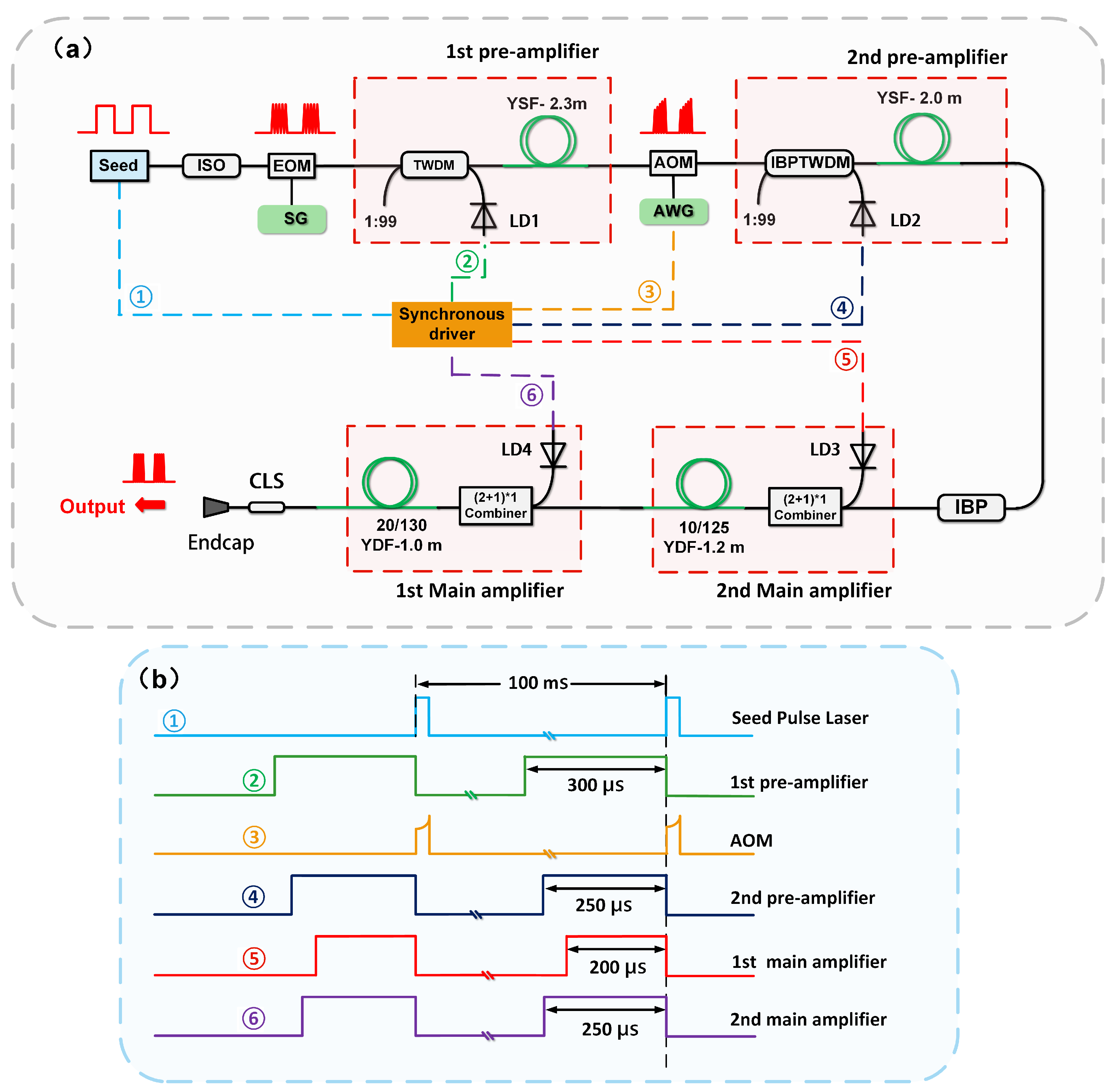
The schematic structure of the laser system setup is illustrated in Figure 2a and comprises four primary sections: a pulse seed source, a high-frequency modulation unit, a waveform compensation module, two pre-amplifier stages, and two main amplification stages. The pulse seed source (homemade) is a polarization-maintaining (PM) 1064 nm laser. The pulse duration is 5.5 µs and the repetition rate is 10 Hz. An isolator (ISO) is used to protect the pulse seed from optical feedback. The seed laser is directed into a high-bandwidth EOM (iXblue, Denver, CO, USA). The EOM has a bandwidth of 10 GHz and an insertion loss of 3.5 dB and is controlled by a signal generator (N5181B, Keysight Inc, Santa Rosa, CA, USA). The seed laser is modulated into a burst-mode laser by an EOM. To compensate for the energy loss caused by the EOM and AOM, two PM fiber pre-amplifier stages are incorporated into the system. A highly doped PM Yb3+ single-mode fiber with an absorption coefficient of 250 dB/m at 976 nm is used as the gain medium for the pre-amplifier stages. Four hundred-milliwatt single-mode 976 nm laser diodes (LDs) are used as pump sources. During the pre-amplifier stage, a taper/wavelength division multiplexing (TWDM) setup is employed to couple the pump laser to the single-mode gain fiber. The TWDM has a 1:99 coupling ratio, with the 1% port serving to monitor the burst seed characteristics. The waveform compensation section comprises a high-extinction-ratio AOM (extinction ratio > 20 dB, Gooch & Housego PLC and G&H Ilminster, Somerset, UK) and an arbitrary waveform generator (AWG). The AOM enables the pre-compensation waveform program to reform the temporal shape of the pulses. In the second stage of the pre-amplifier, an isolator/bandpass/taper/wavelength division multiplexing (IBPTWDM) device with a 3 dB bandwidth of 2 nm is connected to the AOM. This component serves to suppress ASE in the frequency domain and isolate any reverse return light. The 1% port of the IBPTWDM allows for monitoring of the characteristics of the pre-compensation waveform generated by the AOM.
The microsecond burst-mode seed laser is subsequently amplified through two primary fiber amplifier stages. The first main amplifier is composed of a 1.2 m Yb3+-doped double-cladding polarization-maintaining fiber, which has core and cladding diameters of 10 μm and 125 μm, respectively, as well as a cladding absorption value of 4.8 dB/m at 976 nm. The pump source is a 976 nm laser diode (LD) with a maximum average power of 9 W. Both the burst-mode seed laser and the pump laser are introduced into the first main amplifier via a (2 + 1) × 1 signal-pump combiner. The secondary main amplifier utilizes a PM Yb3+-doped fiber, the core and cladding diameters of which are 20 μm and 130 μm, respectively. It is pumped by a 976 nm LD with an output power level of 9 W. The absorption coefficient of the gain fiber is 5.1 dB/m at 976 nm, and its length is 1 m. To maintain the polarization characteristics of the system, all optical components within the amplifier are polarization-maintaining devices. Meanwhile, to reduce the amount of cladding light and suppress backward reflections, an endcap with a cladding light stripper (CLS, homemade) is spliced to the gain fiber.
Considering that the system operates at a low repetition rate of 10 Hz, a multi-stage synchronous pulse pumping method is used in all amplifier stages to reduce the ASE [29,30]. The time sequence for synchronous triggering at each stage is as shown in Figure 2b. The AOM pre-compensation pulse is strictly aligned with the laser seed pulse, and the trailing edge of the laser seed pulse coincides with the leading edge of the pump pulse, thus allowing the upper stored energy to be consumed by the pump and reducing the extraction of stored energy by the ASE [31]. The pump pulse widths are 300 μs (first pre-amplifier) and 250 μs (second pre-amplifier), and 200 μs (first main amplifier) and 250 μs (second main amplifier) for the pre-amplifier and main amplifier, respectively. It is worth noting that the pump pulse width is experimentally optimized to achieve a different pump pulse energy, suppress ASE, and maximize the pumping efficiency.
In this study, a high-bandwidth oscilloscope (10Zi-A, Teledyne Lecroy Inc, New York, NY, USA) is utilized for monitoring the temporal laser pulse train and radio frequency (RF) spectrum. Additionally, an optical spectrum analyzer (AQ6370, Yokogawa Test & Measurement Corporation, Tokyo, Japan) is employed to detect the optical spectrum. Moreover, an energy meter (PE9-ES-C, Ophir Inc, Jerusalem, Israel) and a power meter (3A, Ophir Inc, Jerusalem, Israel) are utilized for relative measurements of the output energy (<100 μJ) and the pump pulse power (<3 mW).

3. Experimental Results and Discussion

3.1. Characteristic Pulse Seed and Waveform Pre-Compensation

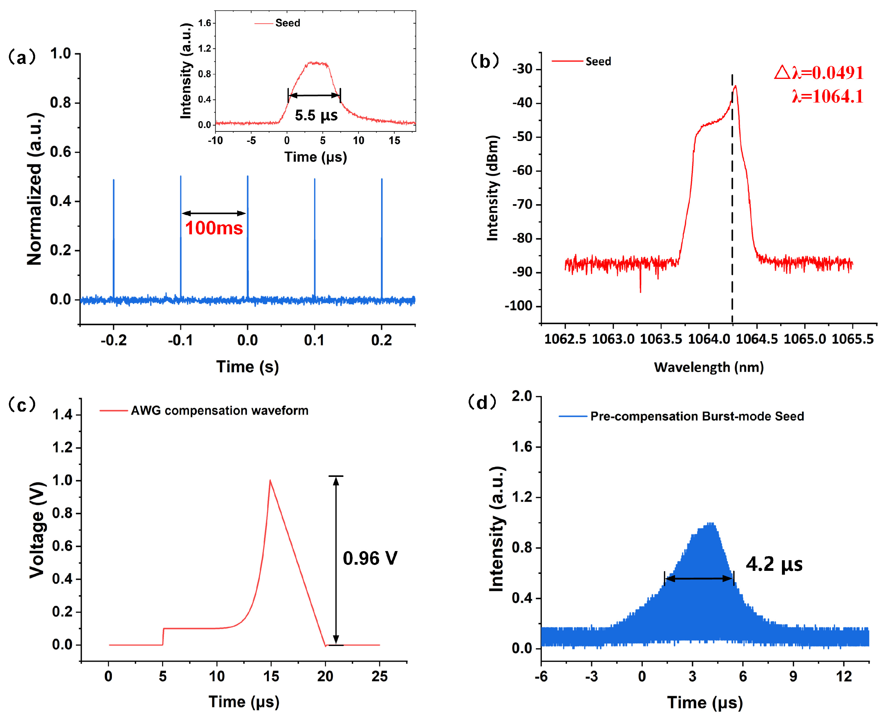
In this experiment, a multi-channel synchronous driver generated 10 Hz trigger signals to activate the seed. The characteristics of the pulse seed source, as shown in Figure 3a, indicate that the pulse seed has a full width at half maximum (FWHM) of approximately 5.5 μs, with a 100 ms separation between twin pulses. The pulse energy of the pulse seed is around 1.67 µJ. The spectrum of the microsecond pulse seed in Figure 3b shows that the center wavelength is 1064.1 nm and the 3 dB bandwidth is 0.0491 nm. During amplification, the SG generates a sine signal of 1 GHz to the EOM, which modulates the microsecond pulse laser into a burst-mode pulse laser with an intra-burst pulse frequency of 1 GHz. The frequency of the SG can be adjusted to modulate the intra-burst pulse repetition rates of the burst-mode laser. The time-domain waveform of the burst-mode pulse seed can be monitored at the 1% port of the TWDM. The first pre-amplifier boosts the energy of the burst-mode seed to 20.75 μJ. An AWG and an AOM are used for waveform pre-compensation of the burst-mode pulse seed. The AWG generates a front-edge depressed electrical waveform that is sent to the AOM. The AOM receives the electrical waveform and then depresses the front edge of the seed source of the rectangular pulse waveform to compensate for the gain saturation effect in the fiber amplification, so that the final output of the amplifier’s pulse waveform presents a rectangular envelope. Compared to directly compensating for the fiber seed with an AWG, the AOM has advantages in terms of the insertion loss and its flexibility in waveform compensation.
The AWG pre-compensation waveform is based on the Frantz–Nodvik equations [32]. The output pulse waveform is linked to the input pulse waveform through a gain function (1).
I i n p u t ( t ) = I o u t p u t ( t ) G ( t )
where Ioutput(t) is the output waveform and Iinput(t) is the input waveform. G(t) is a time-dependent gain that is determined by the magnification of the amplifier. It can also be seen as a transfer function between the input pulse waveform Ioutput(t) and the output pulse waveform Iinput(t). G(t) is given by a simple exponential function [33]:
G ( t ) = 1 + ( G 0 1 ) exp ( E o u t ( t ) E s a t )
G0 is the small-signal gain. Esat is the saturation energy. The input pulse waveform of the target pulse waveform can be expressed as:
I i n p u t ( t ) = I o u t p u t ( t ) 1 + ( G 0 1 ) exp ( E o u t ( t ) E s a t )
Thus, when solving Ioutput(t), it is necessary to know the parameter G0 and the saturation energy Esat. For a given pump power, G0 and Esat can be obtained by means of experimental testing. Figure 3c illustrates the pre-compensation program generated by the AWG, in which the electrical signal waveform voltage is 0.96 V. The pre-compensated envelope is loaded to the AOM through a driver.

3.2. The Performance of Burst-Mode Pulse Fiber Amplifier

3.2.1. The Outputting Energy, the Spectrum, and the Temporal Envelope

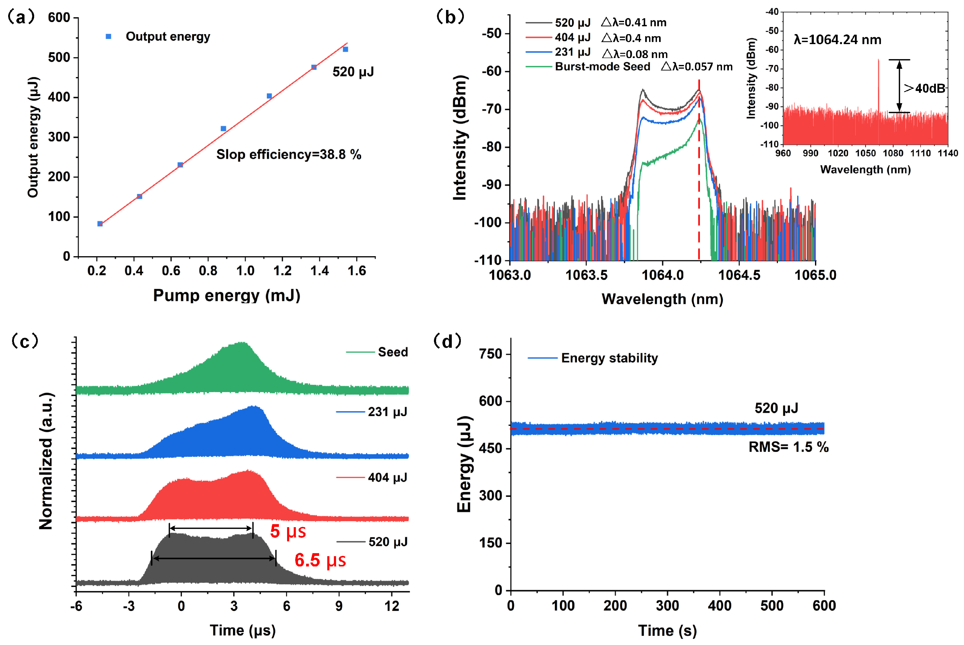
The output energy in relation to the input pump energy of the amplifier is shown in Figure 4a. The output energy of the amplifier increases linearly with the pump energy. the maximum output energy of the burst-mode laser is 520 μJ when the injected pump energy is 1.54 mJ. The amplifier demonstrates a slope efficiency of 33.8%. Figure 4b illustrates the spectral characteristics of the burst-mode laser at different output energy levels, showing a center wavelength of 1064.24 nm. The signal-to-noise ratio exceeds 40 dB, indicating the absence of cladding light and ASE at the maximum energy output. However, the 3 dB bandwidth of the spectrum expands from 0.057 nm in the burst-mode seed to 0.41 nm at an output energy of 520 μJ. Further, the maximum 3 dB bandwidth of the amplifier is within the optimal emission line of Nd: YAG crystal [34]. This suggests that the energy can be scaled through solid hybrid amplification. Figure 4c shows the variation in the time domain envelope of the burst-mode pulse at different energy levels. It shows that the leading edge of the burst pulse rises with increasing amplified energy due to gain saturation effects. At an output energy of 520 μJ, a nearly flat-top pulse envelope is achieved. This indicates the successful mitigation of gain saturation effects through pre-compensation. The FWHM and flat-top width of the burst-mode pulse are measured at 6.5 μs and 5 μs, respectively, at 520 μJ. To characterize the flat-top of the burst pulse envelope, we define an M factor, which can be expressed as follows:
M = 1 P a v e r a g e × i = 1 n ( P i P a v e r a g e ) 2 n × 100 %
Paverage is the average power of the burst laser and Pi is the peak power of the burst laser at different times. It is worth noting that, when calculating the F-factor at 520 uJ energy, we exclude the influence of the rising and falling edges of the envelope and only calculate the top envelope for the duration of 5 μs. Through calculation, the flat top factor of the burst envelope was determined to be M < 5%. In addition, using the burst energy, the peak power and the average power can be calculated by Formula (5):
E = τ × P p e a k × k = P a v e r a g e F × k
where E is the burst energy, τ is the FWHM of the burst laser pulse, Ppeak is the peak power of the burst laser, F is the repetition rate of the burst laser, and k is the duty cycle of the intra-burst pulse at 50%. Therefore, we achieve a maximum peak power of 160 W and an average power of 0.01 W for the burst laser system. To evaluate the system stability, we monitor the burst-mode pulse energy for 10 min at 520 μJ. The result is shown in Figure 4d. We calculate the root mean square (RMS) of the energy fluctuation to be 1.5%, indicating that the amplifier maintains a favorable energy stability.

3.2.2. The Intra-Burst Frequency Tuning Ability and Jitter

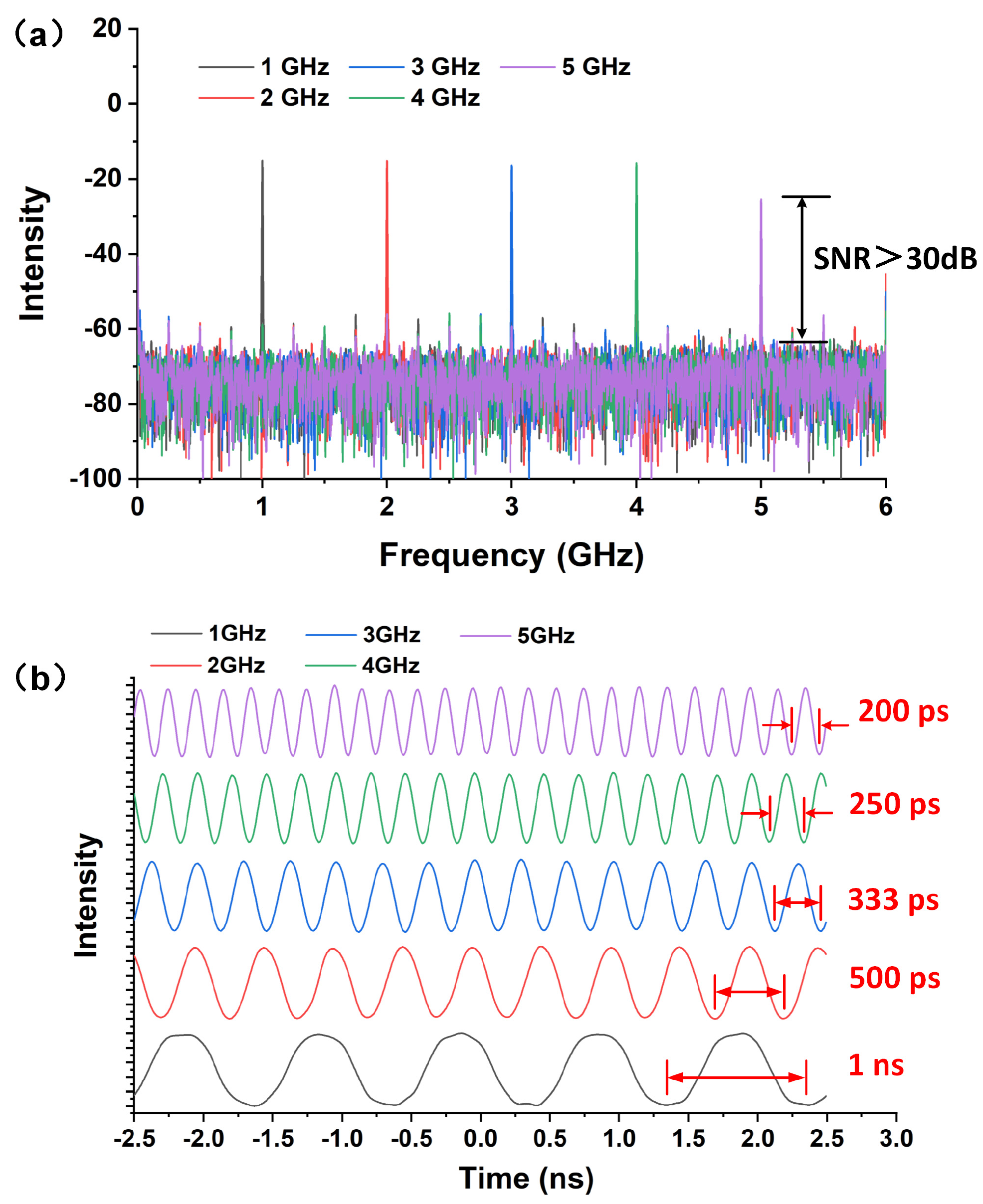
In the experiment, we use a high-speed photoelectric detector (UPD-35-UVIR-D, Alphalas Inc, Göttingen, Germany) with a bandwidth of 40 GHz, along with a 36 GHz oscilloscope (10Zi-A, Teledyne Lecroy Inc, New York, NY, USA) to measure the intra-burst pulse RF spectrum of the burst-mode laser. By varying the SG frequency, the intra-burst pulse repetition rates of the amplifier can be adjusted in real time. Figure 5a shows the RF spectrum of the amplifier operating at different intra-burst pulse repetition rates. The repetition rates range from 1 to 6 GHz with a step size of 1 GHz. This shows that the minimum signal-to-noise ratio (SNR) exceeds 30 dB, indicating that almost all the power can be used to generate alternative microwave signals. Figure 5b illustrates the tunable intra-burst pulse duration of from 200 ps to 1 ns at various intra-burst pulse repetition rates of 1–5 GHz with a sinusoidal waveform. It can be seen that the intra-burst pulse maintains a sinusoidal modulation at different frequencies without waveform distortion.
An important advantage of PMT is the possibility of using multiplexed array synthesis to output higher power; in multiplexed synthesis, laser intra-burst jitter time affects the microwave synthesis efficiency. The jitter can be determined by calculating the standard deviation of the measured time intervals error (TIE) in an oscilloscope. The calculated TIE method is shown in Figure 6a. The TIE can be obtained by measuring the instantaneous deviation between the initial signal (blue line) and the jitter signal (yellow line) at a voltage of 0. The detailed theory of and test methods for the TIE are given in reference [35]. We used a high-bandwidth oscilloscope (10Zi-A, Teledyne Lecroy Inc, New York, NY, USA) to measure the TIE at various frequencies. Notably, during the testing process, we assessed the standard deviation of the jitter time for 500 pulses at the maximum energy. The test results show that the jitter time changes with the energy at different intra-burst frequencies of 1–5 GHz, as shown in Figure 6b, revealing that the jitter time does not increase during power amplification. The average jitter times for different energy levels are 4.31 ps, 2.95 ps, 1.83 ps, 1.31 ps, and 0.78 ps for intra-burst frequencies of 1–5 GHz, respectively. This suggests that the jitter time decreases as the frequency increases, which can be attributed to the SG reducing the jitter at higher frequencies. It is worth noting that the jitter time of a laser system is mainly affected by factors such as the laser energy stability, the thermal performance of the system, and the electrical noise of the EOM. Therefore, the jitter time of the system can be reduced by optimizing these factors. The low jitter time of the amplifier has the potential to be used in microwave array synthesis [36].

3.2.3. The Beam Quality

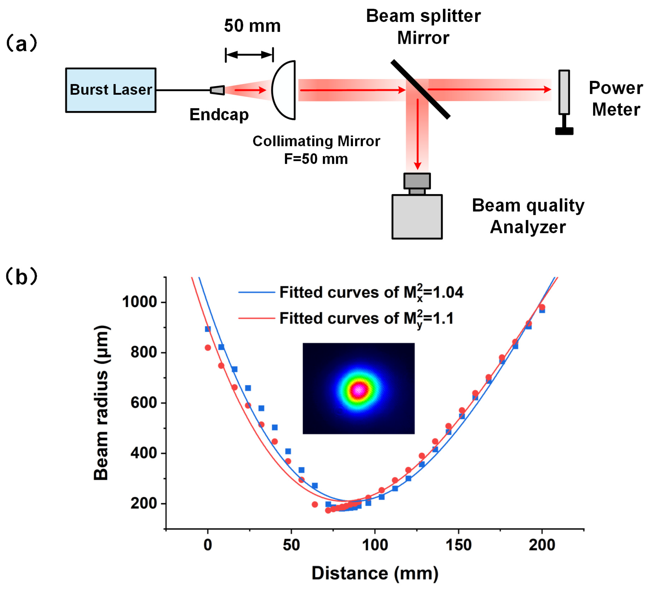
Figure 7a shows a schematic of the beam quality testing system for the burst-mode laser. The beam quality of the burst-mode laser is analyzed using the Thordlab beam quality analysis system (BP209IR2, Thordlabs Inc, Newton, NJ, USA). To collimate the burst-mode laser, a plano-convex 50 mm focal length lens is used. In addition, a beam splitter mirror is employed to split the collimated beam. The mirror has a reflectivity of approximately 99.5%. The mirrors reflect 99.5% of the incident energy into the energy meter to take power measurements, while 0.5% of the transmitted beam is used to measure the beam quality. Figure 7b presents the test results of the beam quality at an output energy of 520 μJ, showing that the beam quality factor is 1.04 for M2X and 1.1 for M2Y.The diameter of the light spot at the waist of the beam is 200 μm.

4. Conclusions

In this study, we have successfully demonstrated a 520 μJ microsecond burst-mode pulse laser with a GHz-adjustable intra-burst pulse. The laser operates at a FWHM of 6.5 μs and a burst laser repetition rate of 10 Hz. By incorporating a synchronous pumping technique, we effectively suppress ASE and nonlinear effects within the system. The laser provides an adjustable intra-burst pulse repetition rate range of 1–5 GHz with a 50% duty cycle sinusoidal modulation, achieving a 5 μs flat-top pulse envelope through the utilization of a pre-compensation waveform generated by an AOM. The beam quality factors M2x and M2y are measured as 1.04 and 1.1, respectively, at the maximum energy output, indicating excellent beam quality. The jitter time for varying energy levels ranges from 4.31 ps to 0.78 ps across the 1–5 GHz intra-burst frequency range.
In addition, the energy of this high-energy microsecond burst-mode laser is significantly enhanced compared to that of reference [21]. This high-energy microsecond pulse cluster source serves as an important reference for the design of future high-energy burst-mode lasers. In comparison with that of reference [22], this laser exhibits a notable increase in both energy and tuning range, positioning it as a promising high-energy tunable seed source. This advancement is beneficial for the further amplification of energy and the effective deployment of large-range tunable optical-guided microwave radar systems.
In the future, the tunable burst-mode laser can be further amplified as an optical drive source for high-power, large-bandwidth microwave photon (MWP) radar applications. At the same time, the high energy, long duration, and wide bandwidth of burst-mode lasers also make them potentially applicable as pulse sources for high-speed optical communications, the high-precision processing of special materials, and LIDAR ranging.

Author Contributions

Conceptualization, Y.G. and X.N. and J.Y.; Conceptualization and supervision, T.X. and J.L.; methodology and formal analysis, Y.G., X.N. and J.Y.; investigation, Y.G. and M.Y.; Writing—Original draft, Y.G., J.Y., L.W., T.X. and J.L.; Conceptualization, supervision, and writing—review and editing, Y.G.; Data curation and experimental setup, Y.G., L.W. and J.Y; Experimental setup, Y.G. and X.N. and M.Y.; project administration and supervision, T.X. and J.L.; supervision, J.L.; funding acquisition, T.X. and J.Y. All authors have read and agreed to the published version of the manuscript.

Funding

This work was supported in part by the National Natural Science Foundation of China under Grant 62071477 and Grant 62101577 and in part. Postgraduate Scientific Research Innovation Project of Hunan Province under Grant QL20230011.

Institutional Review Board Statement

Not applicable.

Informed Consent Statement

Not applicable.

Data Availability Statement

The original contributions presented in the study are included in the article; further inquiries can be directed to the corresponding author.

Acknowledgments

The authors would like to thank engineer Yuchen Liu for his help in the experiments.

Conflicts of Interest

The authors declare no conflicts of interest.

References

  1. Horowitz, M.; Barad, Y.; Silberberg, Y. Noiselike pulses with a broadband spectrum generated from an erbium-doped fiber laser. Opt. Lett. 1997, 22, 799–801. [Google Scholar] [CrossRef]
  2. Kobtsev, S.; Komarov, A. Noise-like pulses: Stabilization, production, and application. J. Opt. Soc. Am. B 2024, 41, 1116. [Google Scholar] [CrossRef]
  3. Obergfell, D.; Azarhoushang, B.; Lasagni, A.F. Investigation of Ablation Efficiency of Stainless Steel Using Pulsed Lasers in Burst Mode. Adv. Eng. Mater. 2023, 25, 2300757. [Google Scholar] [CrossRef]
  4. Kawabata, S.; Bai, S.; Obata, K.; Miyaji, G.; Sugioka, K. Two-dimensional laser-induced periodic surface structures formed on crystalline silicon by GHz burst mode femtosecond laser pulses. Int. J. Extrem. Manuf. 2023, 5, 015004. [Google Scholar] [CrossRef]
  5. Li, G.; Yan, A.; Li, Z.; Xing, S.; Shen, W.; Shi, J.; Li, Z.; Shen, C.; Chi, N.; Zhang, J. Burst-Mode Signal Reception for 200 G Coherent Time and Frequency Division Multiplexing Passive Optical Network. J. Light. Technol. 2025, 43, 429–438. [Google Scholar] [CrossRef]
  6. van Veen, D.; Houtsma, V.; Porto, S.; Basavanhally, N.; Bolle, C.; Schmuck, H. Wavelength-Stable Burst-Mode Laser for Next-Generation PONs. J. Opt. Commun. Netw. 2018, 11, A155–A165. [Google Scholar] [CrossRef]
  7. Li, G.; Zhou, Q.; Xu, G.; Wang, X.; Han, W.; Wang, J.; Zhang, G.; Zhang, Y.; Song, S.; Gu, S. Lidar-radar for underwater target detection using a modulated sub-nanosecond Q-switched laser. Opt. Laser Technol. 2021, 142, 107234. [Google Scholar] [CrossRef]
  8. Long, M.; Yang, Y.; Yang, C.; Zhang, H.; Meng, J.; Ding, J.; Deng, H.; Bai, Z.; Zhang, Z. 1 kHz Burst-Mode Infrared 1064 nm Picosecond Laser for Space Debris Laser Ranging. J. Space Technol. Appl. 2024, 4, 245–255. [Google Scholar] [CrossRef]
  9. Chu, X.; Meng, J.; Wang, H.; Zhu, D.; Yuan, Y.; Huang, L.; Xiang, Z.; Han, J.; Deng, B.; Cui, Y.; et al. Influence of Nitrogen Doping in Vanadium- Compensated 4H-SiC on Transient Photocurrent Response for Photoconductive Microwave Generation. IEEE Photonics Technol. Lett. 2024, 36, 531–534. [Google Scholar] [CrossRef]
  10. Huang, J.; Hu, L.; Yang, X.; Sun, Y.; Li, X.; Liu, C. Modeling and Simulation of Fe-Doped GaN PCSS in High-Power Microwave. IEEE Trans. Electron Devices 2023, 70, 3489–3495. [Google Scholar] [CrossRef]
  11. Gu, Y.; Yao, J.; Yue, N.; Yi, M.; Wang, L.; Xun, T.; Yang, H.; Liu, J.; Ge, X.; He, J. Fiber-Induced Optical Reflective Cavity in a High-Voltage SiC Photoconductive Switch to Improve Photoelectric Responsivity. IEEE J. Electron Devices Soc. 2023, 12, 256–261. [Google Scholar] [CrossRef]
  12. Zhang, J.; Zhang, D.; Fan, Y.; He, J.; Ge, X.; Zhang, X.; Ju, J.; Xun, T. Progress in narrowband high-power microwave sources. Phys. Plasmas 2020, 27, 010501. [Google Scholar] [CrossRef]
  13. Niu, X.; Wu, Q.; Wang, B.; Yao, J.; Chu, X.; Yi, M.; Gu, Y.; Wang, L.; Xun, T.; Yang, H. Test of KW Class Photonic Microwave Generation Using Vanadium-Compensated 6H-SiC PCSS and Burst-Mode-Operation Pulse Laser. IEEE Photonics J. 2023, 15, 5500407. [Google Scholar] [CrossRef]
  14. Chu, X.; Xun, T.; Wang, L.; Yang, H.; Liu, J.; He, J.; Zhang, J. Wide-Range Frequency-Agile Microwave Generation up to 10 GHz Based on Vanadium-Compensated 4H-SiC Photoconductive Semiconductor Switch. IEEE Electron Device Lett. 2022, 43, 1013–1016. [Google Scholar] [CrossRef]
  15. Ortega-Gonzalez, F.J.; Tena-Ramos, D.; Patino-Gomez, M.; Pardo-Martin, J.M.; Madueno-Pulido, D. High-Power Wideband L-Band Suboptimum Class-E Power Amplifier. IEEE Trans. Microw. Theory Tech. 2013, 61, 3712–3720. [Google Scholar] [CrossRef]
  16. Fang, W.-R.; Huang, W.-H.; Huang, W.-H.; Li, J.-W.; Fu, C.; Wang, L.-L.; He, T.-W.; Cao, Y. X-Band High-Efficiency High-Power GaN Power Amplifier Based on Edge-Triggered Gate Modulation. IEEE Microw. Wirel. Compon. Lett. 2020, 30, 884–887. [Google Scholar] [CrossRef]
  17. Capmany, J.; Mora, J.; Gasulla, I.; Sancho, J.; Lloret, J.; Sales, S. Microwave Photonic Signal Processing. J. Light. Technol. 2013, 31, 571–586. [Google Scholar] [CrossRef]
  18. Marpaung, D.; Yao, J.; Capmany, J. Integrated microwave photonics. Nat. Photonics 2019, 13, 80–90. [Google Scholar] [CrossRef]
  19. Ma, C.; Yang, Y.; Liu, C.; Fan, B.; Ye, X.; Zhang, Y.; Wang, X.; Pan, S. Microwave Photonic Imaging Radar with a Sub-Centimeter-Level Resolution. J. Light. Technol. 2020, 38, 4948–4954. [Google Scholar] [CrossRef]
  20. Yu, H.; Zhang, J.; Qi, Y.; Zhang, L.; Zou, S.; Wang, L.; Lin, X. 85-W Burst-Mode Pulse Fiber Amplifier Based on a Q-Switched Mode-Locked Laser with Output Energy 0.5 mJ per Burst Pulse. J. Light. Technol. 2015, 33, 1761–1765. [Google Scholar] [CrossRef]
  21. Zhang, J.; Li, D.; Cheng, W.; Zhang, H. Amplification and frequency quadrupling of picosecond long duration burst-mode laser. Opt. Laser Technol. 2023, 158, 108848. [Google Scholar] [CrossRef]
  22. Gu, Y.; Niu, X.; He, T.; Yi, M.; Yao, J.; Wang, L.; Xun, T.; Liu, J. 26.6 μJ microsecond tunable burst-mode pulsed laser based on synchronous pumping. In Proceedings of the International Conference on Optics and Machine Vision (ICOMV 2024), Nanchang, China, 19–21 January 2024; SPIE: St Bellingham, WA, USA, 2024; pp. 55–59. [Google Scholar]
  23. Huang, C.; Deibele, C.; Liu, Y. Narrow linewidth picosecond UV pulsed laser with mega-watt peak power. Opt. Express 2013, 21, 9123–9131. [Google Scholar] [CrossRef] [PubMed]
  24. Li, F.; Zhao, W.; Fu, Y.; Xing, J.; Wen, W.; Wang, L.; Li, Q.; Cao, X.; Zhao, H.; Wang, Y. High-Power GHz Burst-Mode All-Fiber Laser System with Sub 300 fs Pulse Duration. Photonics 2024, 11, 570. [Google Scholar] [CrossRef]
  25. Li, S.C.; Huang, T.L.; Hsieh, Y.H.; Liang, H.C.; Huang, K.F.; Chen, Y.F. Generation and characterization of burst modes in passively mode-locked lasers with internal Fabry–Perot cavities. Opt. Lett. 2019, 45, 61–64. [Google Scholar] [CrossRef]
  26. Han, L.; Wang, T.; Liu, R.; Ma, W.; Zhao, Y.; Fu, Q.; Jiang, H. Generation of Flat-Top Q-Switched Envelope Dissipative Soliton Resonance Pulse in Passively Mode-Locked Fiber Laser. IEEE Photonics J. 2020, 12, 7101508. [Google Scholar] [CrossRef]
  27. Kerse, C.; Kalaycıoğlu, H.; Elahi, P.; Akçaalan, Ö.; Ilday, F.Ö. 3.5-GHz intra-burst repetition rate ultrafast Yb-doped fiber laser. Opt. Commun. 2016, 366, 404–409. [Google Scholar] [CrossRef]
  28. Barua, S.; Das, N.; Nordholm, S.; Razaghi, M. Comparison of pulse propagation and gain saturation characteristics among different input pulse shapes in semiconductor optical amplifiers. Opt. Commun. 2016, 359, 73–78. [Google Scholar] [CrossRef]
  29. Šajn, M.; Petelin, J.; Agrež, V.; Vidmar, M.; Petkovšek, R. DFB diode seeded low repetition rate fiber laser system operating in burst mode. Opt. Laser Technol. 2017, 88, 99–103. [Google Scholar] [CrossRef]
  30. Zhang, H.; Deng, D.; Zu, J.; Chen, J.; Li, D. Numerical Model of Chirped Pulse Amplification in Pulsed Synchronously Pumped Low-Repetition-Rate Fiber Amplifiers. IEEE Photonics J. 2021, 13, 1500511. [Google Scholar] [CrossRef]
  31. Zhang, H.; Shen, X.; Chen, D.; Zheng, C.; Yan, P.; Gong, M. High energy and high peak power nanosecond pulses generated by fiber amplifier. IEEE Photonics Technol. Lett. 2014, 26, 2295–2298. [Google Scholar] [CrossRef]
  32. Frantz, L.M.; Nodvik, J.S. Theory of Pulse Propagation in a Laser Amplifier. J. Appl. Phys. 1963, 34, 2346–2349. [Google Scholar] [CrossRef]
  33. Schimpf, D.N.; Ruchert, C.; Nodop, D.; Limpert, J.; Tünnermann, A.; Salin, F. Compensation of pulse-distortion in saturated laser amplifiers. Opt. Express 2008, 16, 17637–17646. [Google Scholar] [CrossRef] [PubMed]
  34. Černe, L.; Petelin, J.; Petkovšek, R. Femtosecond CPA hybrid laser system with pulse-on-demand operation. Opt. Express 2020, 28, 7875–7888. [Google Scholar] [CrossRef] [PubMed]
  35. WaveRunner 9000 and WaveRunner 8000-R Oscilloscopes Operator’s Manual; Teledyne LeCroy: Chestnut Ridge, NY, USA, 2022.
  36. Niu, X.; Gu, Y.; Chu, X.; Yao, J.; Yi, M.; Wang, L.; Xun, T. Primary study on time control technology of active phased array based on photoconductive microwave source. High Power Laser Part. Beams 2024, 36, 013005. [Google Scholar] [CrossRef]
Figure 1. Schematic diagram of high-power microwave photon radar, DC: direct-current, PCSS: photoconductive semiconductor switch, RF: radio frequency.
Photonics 12 00097 g001
Figure 2. (a) Schematic diagram of microsecond burst-mode GHz-tunable fiber laser system. ISO: isolator, EOM: electro-optic modulator, TWDM: taper/wavelength division multiplexing, IBPTWDM: isolator/bandpass/taper/wavelength division multiplexing, IBP: isolator and bandpass filter hybrid, YSF: ytterbium-doped single-mode fiber, YDF: ytterbium-doped fiber; AOM: acousto-optic modulator, LD: laser diode, AWG: arbitrary waveform generator, SG: signal generator, (b) schematic diagram of the synchronously triggered time sequence for each stage.
Photonics 12 00097 g002
Figure 3. (a) The characteristics of the single pulse seed, (b) the spectrum of the microsecond pulse seed, (c) the AWG pre-compensation signal waveform, (d) pre-compensated temporal waveform of the burst-mode pulse seed. The pre-compensated temporal shape of the burst-mode laser is depicted in (d), where the temporal shape aligns with the AWG compensation signal. The FWHM of the pre-compensated envelope is 4.2 μs. The secondary pre-amplifier achieves a maximum energy of 26.6 μJ.
Photonics 12 00097 g003
Figure 4. (a) The output energy in relation to the input pump energy of the amplifier, (b) the spectrum of the amplifier at different output energy levels, (c) the temporal envelope evolution of the burst-mode pulse at different energy levels, (d) the long-term stability of the burst-mode laser measured over 10 min.
Photonics 12 00097 g004
Figure 5. (a) The adjustability of the burst-mode laser frequency within the range of 1–5 GHz, (b) intra-burst pulse period of 200 ps—1 ns is tunable at various intra-burst repetition rates of 1–5 GHz with a sinusoidal waveform.
Photonics 12 00097 g005
Figure 6. (a) Schematic diagram of TIE measurement method, (b) TIE at different frequencies of 1–5 GHz at different stages of the amplifier.
Photonics 12 00097 g006
Figure 7. (a) Experimental configuration of beam quality analysis for the burst-mode laser, (b) the beam quality test results.
Photonics 12 00097 g007
Disclaimer/Publisher’s Note: The statements, opinions and data contained in all publications are solely those of the individual author(s) and contributor(s) and not of MDPI and/or the editor(s). MDPI and/or the editor(s) disclaim responsibility for any injury to people or property resulting from any ideas, methods, instructions or products referred to in the content.