Communication

Propagation Properties of Laguerre–Gaussian Beams with Three Variable Coefficient Modulations in the Fractional Schrödinger Equation

1
School of Information and Electrical Engineering, Hunan University of Science and Technology, Xiangtan 411201, China
2
School of Chemistry and Chemical Engineering, Hunan University of Science and Technology, Xiangtan 411201, China
*
Author to whom correspondence should be addressed.
These authors contributed equally to this work.
Photonics 2025, 12(2), 163; https://doi.org/10.3390/photonics12020163
Submission received: 21 January 2025 / Revised: 12 February 2025 / Accepted: 14 February 2025 / Published: 18 February 2025

Abstract

:
This article investigates the transmission characteristics of Laguerre–Gaussian (LG) beams under cosine modulation, power function modulation and linear modulation based on the variable coefficient fractional Schrödinger equation (FSE), respectively. In the absence of modulation, the LG beam undergoes diffraction-induced expansion as the transmission distance increases, with the degree of spreading increasing with a rising Lévy index. Under the cosine modulation, the evolution of the beam exhibits a periodic inversion, where the higher modulation frequency leads to a shorter oscillation period. The oscillation amplitude enlarges with a higher Lévy index and lower modulation frequency. When taking a power function modulation into account, the beam gradually evolves into a stable structure over propagation, with its width broadening with a growing Lévy index and modulation coefficient. In a linear modulation, the propagation of the LG beam forms a “trumpet-like” structure due to an accelerated diffraction effect. Notably, the transmission of the beam is not affected by the radial and azimuthal indices, but its ring number and phase singularity are changed correspondingly. The beam behaves in a similar evolutionary law under different modulations when the Lévy index is below 1. These findings offer valuable insights for applications in optical manipulation and communication.

1. Introduction

The LG beam has attracted significant research interest due to its unique properties, such as orbital angular momentum and wavefront helical phase, which make it valuable in optical manipulation [1], optical communication [2] and molecular structure determination [3]. In recent years, the LG beam has been extensively studied in the standard Schrödinger system. For example, Peng et al. investigated the transmission characteristics of LG beams with different topological charges in several turbid media by comparing them to Gaussian beams, which contributes to the study of underwater optical communications [4]. On this basis, it was found that LG beams maintain high propagation quality even under strong underwater turbulence [5]. The partially coherent radially polarized LG vortex beams have been proven to be degraded by atmospheric turbulence while simultaneously exhibiting self-rotation, which has potential applications in floating Lidar and remote sensing [6]. Research in LG beam propagation in turbulent atmospheres also confirmed that asymmetric laser beams exhibit enhanced stability against turbulence [7]. An analytical solution for LG beams in weakly compressible turbulence has been derived, which provides a theoretical basis for the application of radial modes to free space communication [8]. Efforts to the generation and control of high-order LG [9] and customized LG beams [10] have further improved the optical communication performance. Recently, the experimental implementation of double-orbital rotational dynamics of nanoparticles in polarized LG beams has been successfully reported [11], and the flexible control of the generation of higher-order LG beams is possible by using a hybrid pumping scheme [12]. These provide new avenues for particle manipulation and multidimensional optical field control.
As an extension of the standard Schrödinger equation, the FSE proposed by Laskin [13] has attracted research interest, particularly in the field of mathematics in recent decades [14]. In 2015, Longhi [15] extended the FSE to the light field through an optical experiment, sparking investigations into beam transport properties in FSE-based systems, for example, the split of super-Gaussian beams [16], generation multiple Hermite–Gaussian solitons [17], irregular interactions between two Airy beams [18] and modulation instabilities [19]. Subsequently, the transport of Airy–Gaussian vortex beams in FSE [20,21] and the generation of random solitons [22] were investigated. External factors have also been introduced to manipulate beam transmission, such as the propagation dynamics of LG beams under noise interference [23], the control of beam transmission with spectral phase modulation [24], and the impact of potential fields on Hermite–Gaussian beams [25]. Experimentally, the researchers modeled Lévy waveguides using programmable hologram technology and observed isolated, split and merged pulses by varying the initial pulse and the Lévy index of the FSE [26]. Based on this result, a nonlinear optical platform is also provided to simulate nonlinear Lévy waveguides. The interaction between the velocity dispersion of the effective fractional group is explored, providing new avenues for the experimental study of nonlinear FSE systems [27].
Recent efforts have also focused on applying different diffraction modulations to further explore the manipulation of the beam. It was observed that the Gaussian beam exhibits periodic oscillations after applying cosine modulation based on FSE, and its evolutionary properties are influenced by the Lévy index and chirp [28]. The evolution of 2D Gaussian beams with different longitudinal modulations [29] and the stable transmission of circular Airy beams [30] were then successively examined. Based on these investigations, Tan et al. demonstrated that the circular Airy [31] and Hermite–Gaussian [32] beams with different modulations could exhibit periodic oscillations, continuous diffusion and gradual stabilization, and they explored the effect of modulation coefficients on beams in detail. These findings show that the transmission characteristics of beams can be effectively regulated by using modulation based on FSE, which has a wide range of applications in optical manipulation and optical communications.
We have previously analyzed the transmission characteristics of Hermite–Gaussian and circular Airy beams in the FSE with variable coefficients. However, there is little research on the propagation characteristics of LG beams under a variable coefficient FSE. Consequently, the work of this paper is aimed at exploring the effect of various parameters on the evolution of LG beams under cosine modulation, power function modulation and linear modulation in the FSE, which will contribute to the application of LG beams in optical communication.

2. Theoretical Model

The evolution of the LG beam in an optical system can be described by the FSE:
i U ( x , y , z ) z = 1 2 D ( z ) ( 2 x 2 2 y 2 ) α 2 U ( x , y , z )
where U ( x , y , z ) is the normalized amplitude, x and y are normalized coordinates, z is the normalized propagation distance, α is the Lévy index, and D ( z ) represents the variable coefficient, which is a function of the z.  ( 2 x 2 2 y 2 ) α 2 is a fractional order Laplace formula with Lévy index. When α = 2 and D ( z ) = 1 , Equation (1) turns into a standard Schrödinger equation.
Applying the Fourier transform, Equation (1) can be written as
i z U ^ ( k x , k y , z ) = 1 2 ( k x 2 + k y 2 ) α 2 U ^ ( k x , k y , z )
where U ^ ( k x , k y , z ) = U ( k x , k y , z ) e i ( k x x + k y y ) d x d y is the Fourier transform of U ( k x , k y , z ) , k x and k y denote the spatial frequencies. The generalized solution of Equation (2) can be written as
U ^ ( k x , k y , z ) = U ^ ( k x , k y , 0 ) e 1 2 ( k x 2 + k y 2 ) α 2 0 z D ( ξ ) d ξ
where U ^ ( k x , k y , 0 ) is the Fourier transform of U ( x , y , 0 ) , the solution of Equation (1) can be written as
U ( x , y , z ) = 1 4 π 2 U ^ ( k x , k y , z ) e i ( k x x + k y y ) d k x d k y
In this paper, the input light field of LG beams as
U ( x , y , 0 ) = F ( p , l ) 2 p ! π ( p + l ) ! [ 2 ( x 2 + y 2 ) ] l e ( x 2 y 2 ) L p l [ 2 ( x 2 + y 2 ) ] e ( i l θ )
where L p l is a Laguerre polynomial, θ is the polar angle, and p and l are radial and azimuthal indices, respectively. Here, we choose p = l = 1 if not specified, and F ( p , l ) stands for the normalization intensity.
The beam width ω during transmission can be expressed as
w = 2 ( x x c ) 2 U 2 d x d y U 2 d x d y
where x c is the center of gravity of the beam:
x c = x U 2 d x d y U 2 d x d y
In this paper, the cosine modulation expression is given by
D z = cos Ω z
Ω is the modulation frequency.
The power function modulation expression is
D z = k z
k represents the modulation coefficient.
The linear modulation expression is
D z = z
As the generalized solution U ( x , y , z ) for the LG beam in FSE is difficult to obtain, we model the numerical evolution of the electric field U ( x , y , z ) during transmission by applying the split-step Fourier method to solve Equation (1).

3. Numerical Simulation Results and Analysis

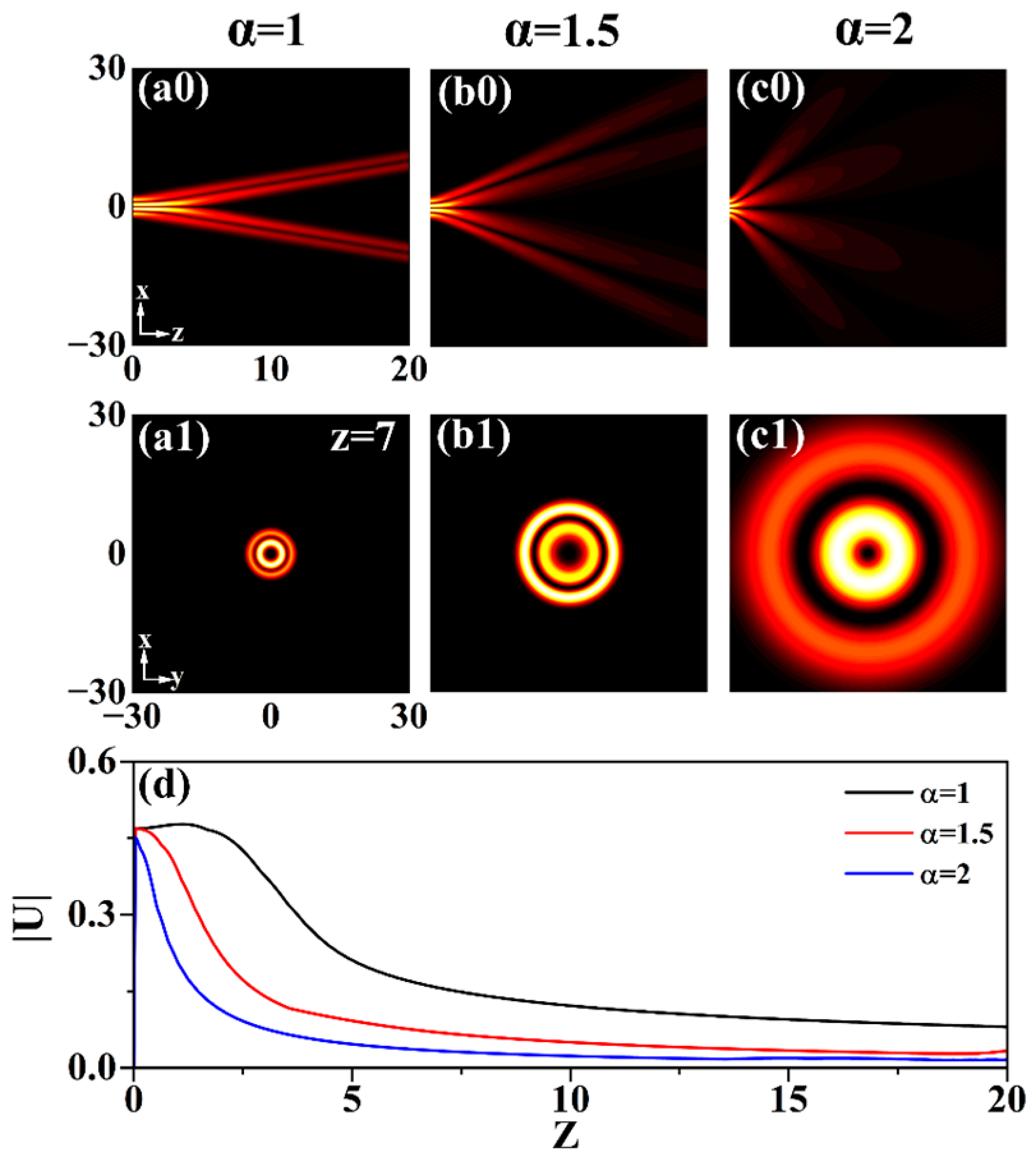
3.1. Without Modulation

Figure 1 shows the transmission characteristics of the LG beam for different Lévy indices α without modulation. From Figure 1(a0–c0), the beam undergoes continuous expansion with increasing transmission distance. A larger Lévy index enhances the diffraction effect, which results in a faster spatial spread of the beam. The spot size exhibits significant enlargement at the same distance (z = 7) due to intensified diffraction, as shown in Figure 1(a1–c1). Figure 1d reveals that the beam energy diminishes progressively with propagation, and the rate of energy reduction accelerates with growing diffraction. Therefore, the energy diffusion of the beam can be effectively controlled by varying α .

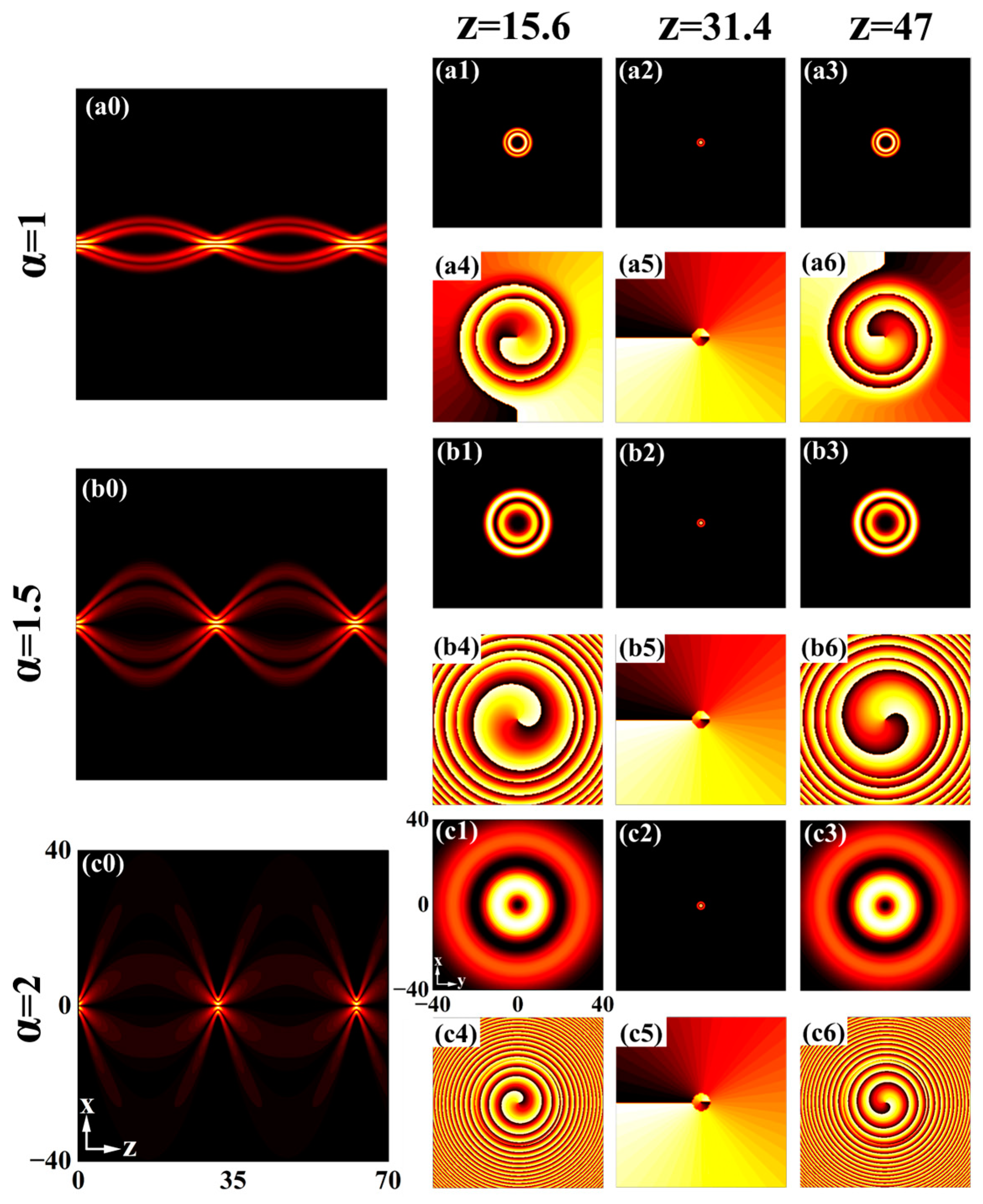
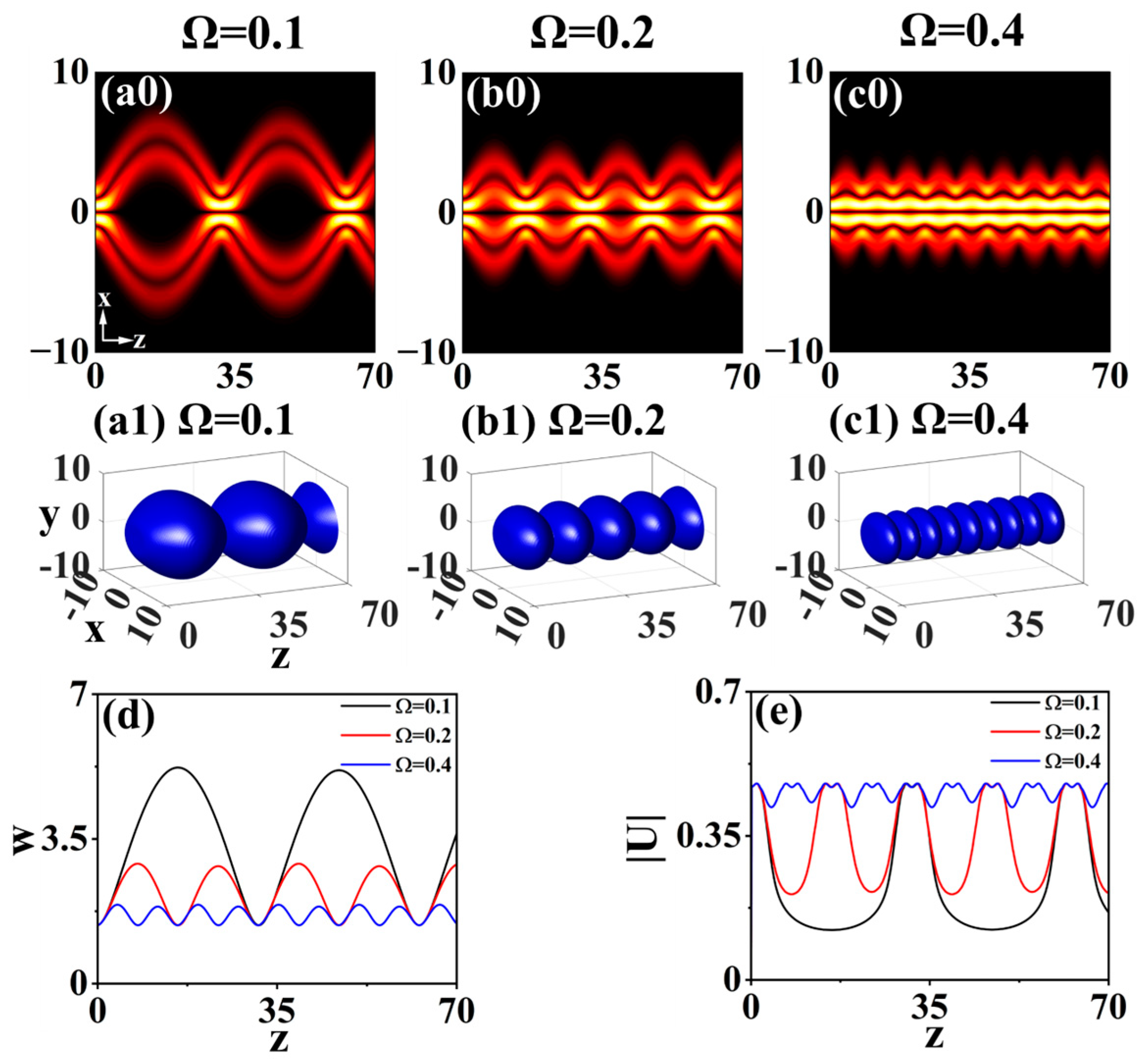
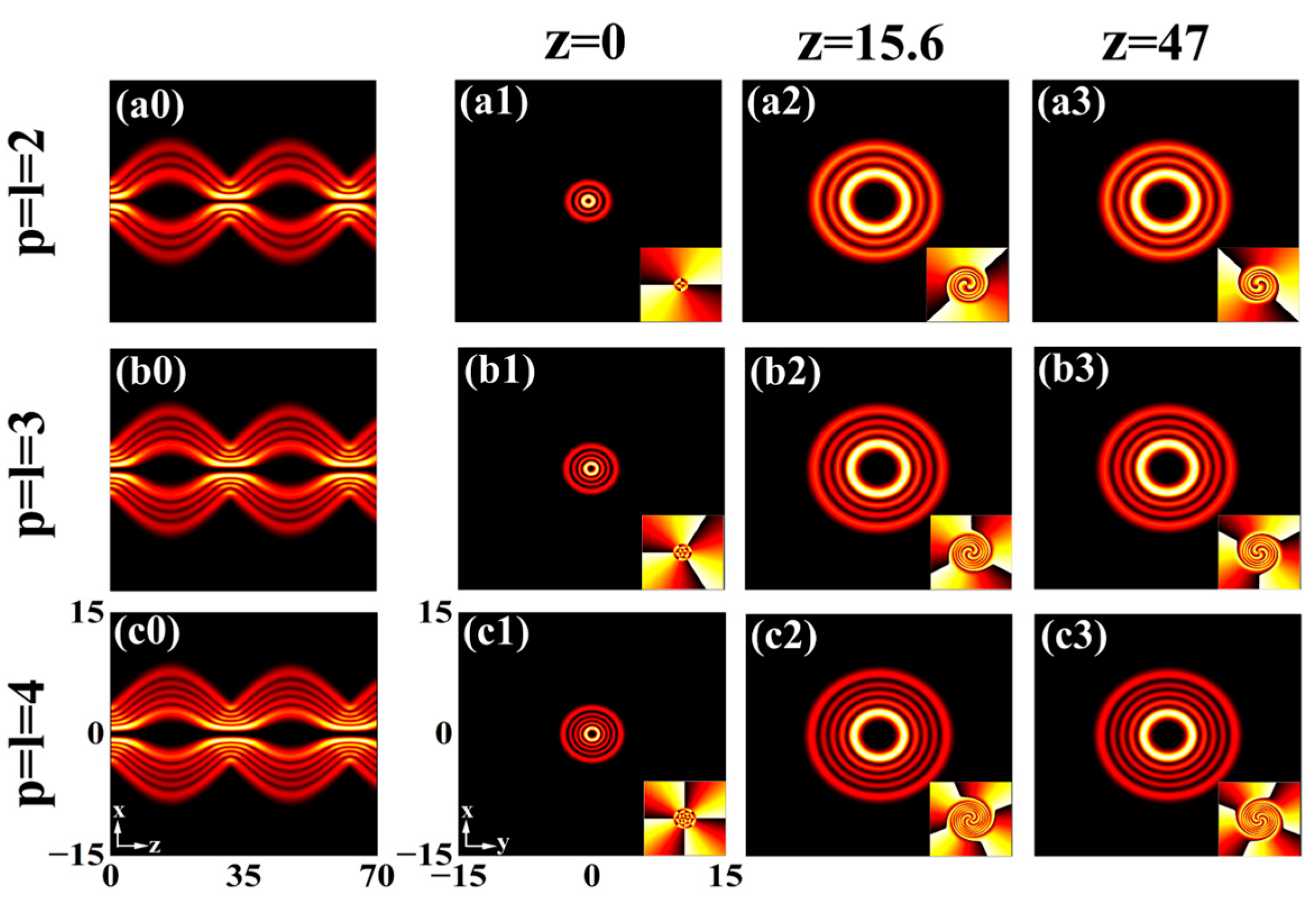
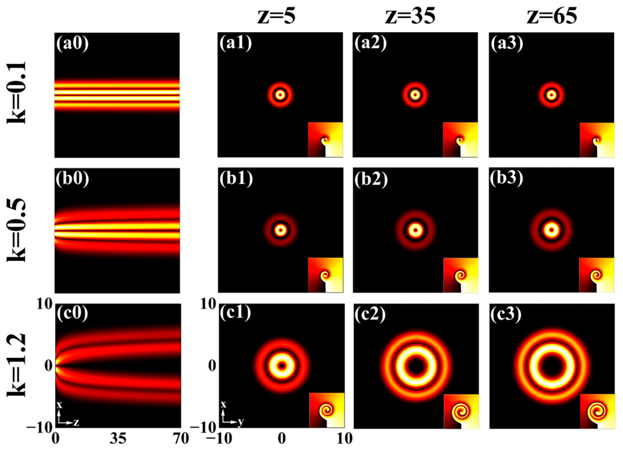
3.2. With Cosine Modulation

Figure 2 illustrates the propagation properties of the LG beam under cosine modulations for different Lévy indices α . In Figure 2(a0–c0), the evolution of the beam exhibits periodic oscillations with transverse amplitude proportional to the Lévy index when applying cosine modulation. To provide a more precise analysis, we consider critical points in the diffraction modulation cycle, where z = 15.6, 31.4, 47 corresponds exactly to 1/4, 1/2 and 3/4 cycles of the cosine modulation. By observing the beam changes at these limit points, we can gain a clearer understanding of the LG beam transition characteristics. The ring size is maximum at z = 15.6 [Figure 2(a1)], and the corresponding phase [Figure 2(a4)] shows a counterclockwise rotation, which reflects the self-rotation of the beam during propagation. Afterwards, the beam shrinks to its initial shape [Figure 2(a2)] and the phase returns to its original state [Figure 2(a5)]. The beam expands to its maximum size [Figure 2(a3)] when z = 47, but this time with a clockwise phase rotation [Figure 2(a6)], which indicates that the beam has a periodic reversal characteristic during transmission. The observed self-rotation of the beam originates from its own orbital angular momentum and the uneven energy distribution during transmission. The effect of cosine-modulated diffraction is responsible for the periodic inversion of this rotation. The beam follows the same evolutionary law as the diffraction effect intensifies, but the size of the beam when defocused expands with a larger α , as shown in Figure 2(b1–c6). Since the beam restores to initial state at z = 31.4, the halo radius and phase distribution are unaffected by α . The physical meaning is that the cosine-modulated diffraction effect induces a periodic oscillation in the beam morphology, governed by a cosine function-dependent transition during propagation. The sign of the diffraction term is the critical point of the transition at D ( z ) = 0 , where the beam reaches its maximum expansion and inverts, with its shape always recovered at D ( z ) = ± 1 .
Figure 3 shows the evolution of the LG beam under different modulation frequencies Ω . In Figure 3(a0–c0), the evolution period of the beam shortens and the constraint force on the beam strengthens as the Ω increases, which leads to a reduction in the transverse amplitude. To provide a more intuitive understanding of the dynamic process of beam evolution, Figure 3(a1–c1) displays the corresponding three-dimensional isosurface maps. It can be seen from Figure 3d that the beam width is inversely proportional to the Ω in a periodic evolution. As the transmission distance grows, the energy of the beam exhibits periodic fluctuations, alternating between decreases and increases. The smaller Ω leads to a greater reduction in energy, accompanied by a longer variation period, as highlighted in Figure 3e.
Figure 4 demonstrates the evolution of the LG beam for different radial and azimuthal indices under cosine modulations. The radial and azimuthal indices are set to be equal in this paper. As can be seen in Figure 4(a0–c0), the periodic evolution of the beam is not influenced by the radial and azimuthal indices. In Figure 4(a1–c1), the number of rings and phase singularities of the initial beam increase with rising radial and azimuthal indices. The ring features the largest size and the phase undergoes successive counterclockwise and clockwise rotations, which suggests that the inversion of the beam remains unaffected by the radial and azimuthal indices, as shown in Figure 4(a2–c3). If the radial and azimuthal indices are not identical values, what happens to the beam transmission characteristics? The radial index p determines the number of rings of the LG beam, which is given by p + 1. The azimuthal index l influences the topological charge of the beam, which is equal to the number of topological charges carried by the beam. A larger value of l leads to a wider hollow area within the beam. If they are not equal, the spot and phase will change accordingly. However, the overall propagation behavior of the beam remains unchanged for the same diffraction modulation.

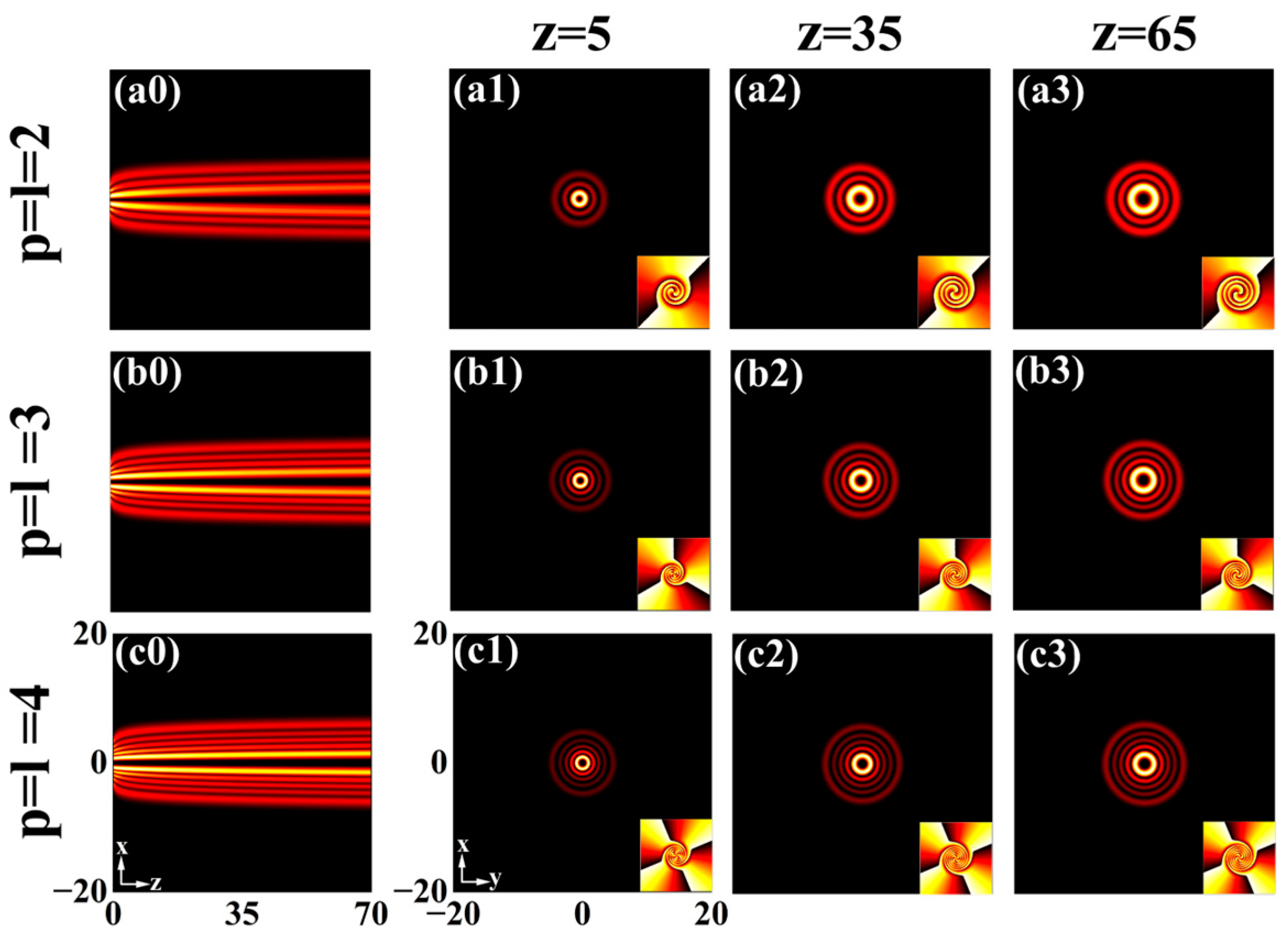
3.3. With Power Function Modulation

In this section, we discuss the impact of power function modulation on the LG beam. Figure 5 presents the evolution of the beam under power function modulations with various different Lévy indices α . In Figure 5(a0), almost diffraction-free transmission over a distance of 70 is achieved when the Lévy index is 1. What happens beyond this distance? The power function modulation gradually mitigates the diffraction effect on the beam as the transmission distance increases. We extend the beam’s transmission distance to z = 5000, and it still maintains stable propagation. From Figure 5(a0–c0), the LG beam gradually evolves into a stable structure as the transmission distance increases. As α increases, the diffraction effect intensifies, leading to greater energy decay and a beam expansion of the transverse amplitude. Simultaneously, the radius of the ring rises (z = 7) as α increases (see Figure 5(a1–c1)). Figure 5(d0) reveals that the beam width initially increases and then gradually stabilizes as the propagation distance grows, and the smaller α leads to earlier stabilization. In Figure 5(d1) the energy of the beam reduces and then remains constant after a certain distance, and the diffraction effect of the beam strengthens as α increases, accelerating energy loss. The corresponding three-dimensional isosurfaces of the beam are clearly shown in Figure 5(a2–c2).
Figure 6 illustrates the evolution of the LG beam for different modulation coefficients k. From Figure 6(a0–c0), the beam maintains a straight and stable transmission when k = 0.1 . However, as k increases, it spreads out at first and then gradually evolves into a steady structure. The reason is that the attenuating effect of the power function modulation on diffraction intensifies as k decreases. Similarly, the radius of the ring remains unchanged in Figure 6(a1–a3), while its size first increases and then stays stable in Figure 6(b1–c3). In order to enhance the efficiency of signal transmission in optical communication, reducing k can improve beam stability, thus facilitating long-distance beam propagation.
Figure 7 presents the transmission characteristics of LG beams with power function modulations for different radial and azimuthal indices. As can be seen in Figure 7(a0–c0), the evolution properties of the beam are similar to those in Figure 5(a0). However, we find that the number of the ring and phase singularity increase with the increase in the radial and azimuthal indices in Figure 7(a1–c3), which is similar to Figure 4(a1–c3). The phase remains constant after a certain angle of counterclockwise rotation, which reflects the rotation properties of the beam.

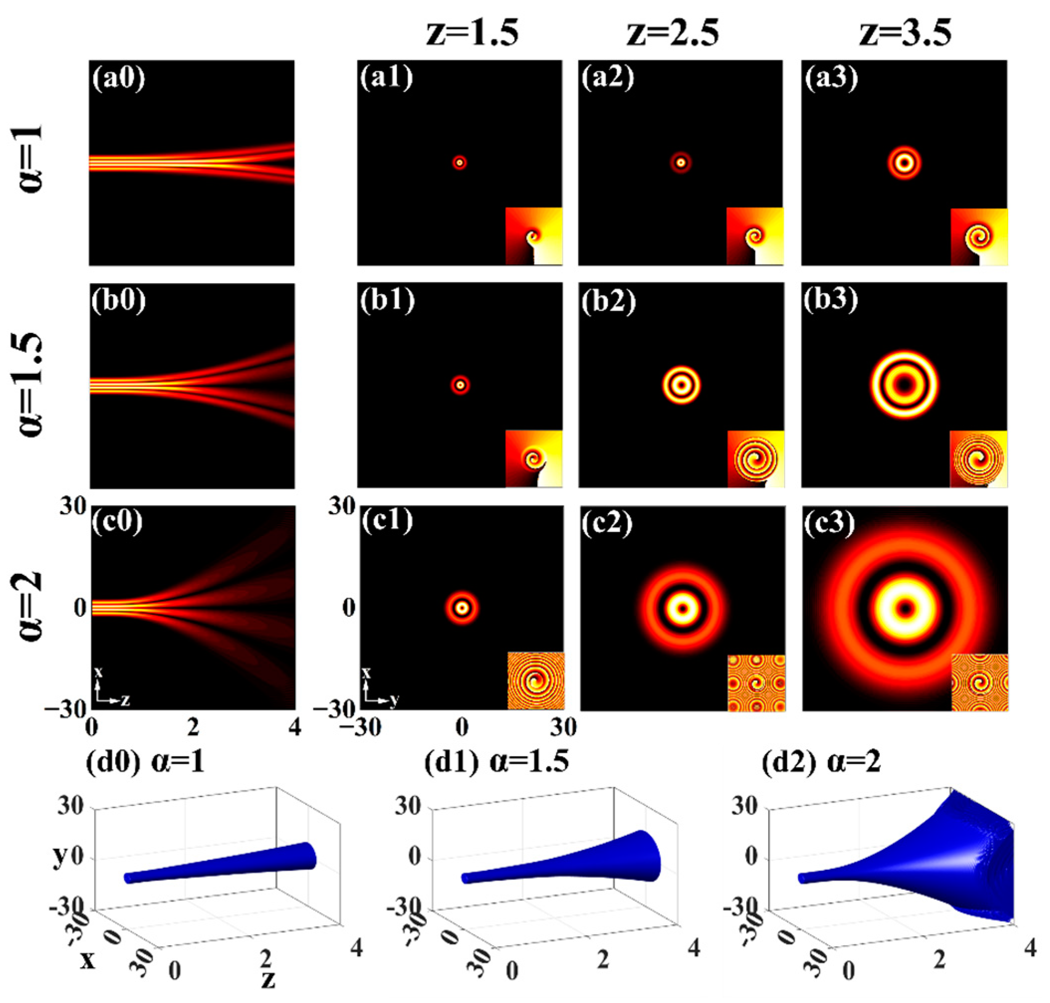
3.4. With Linear Modulation
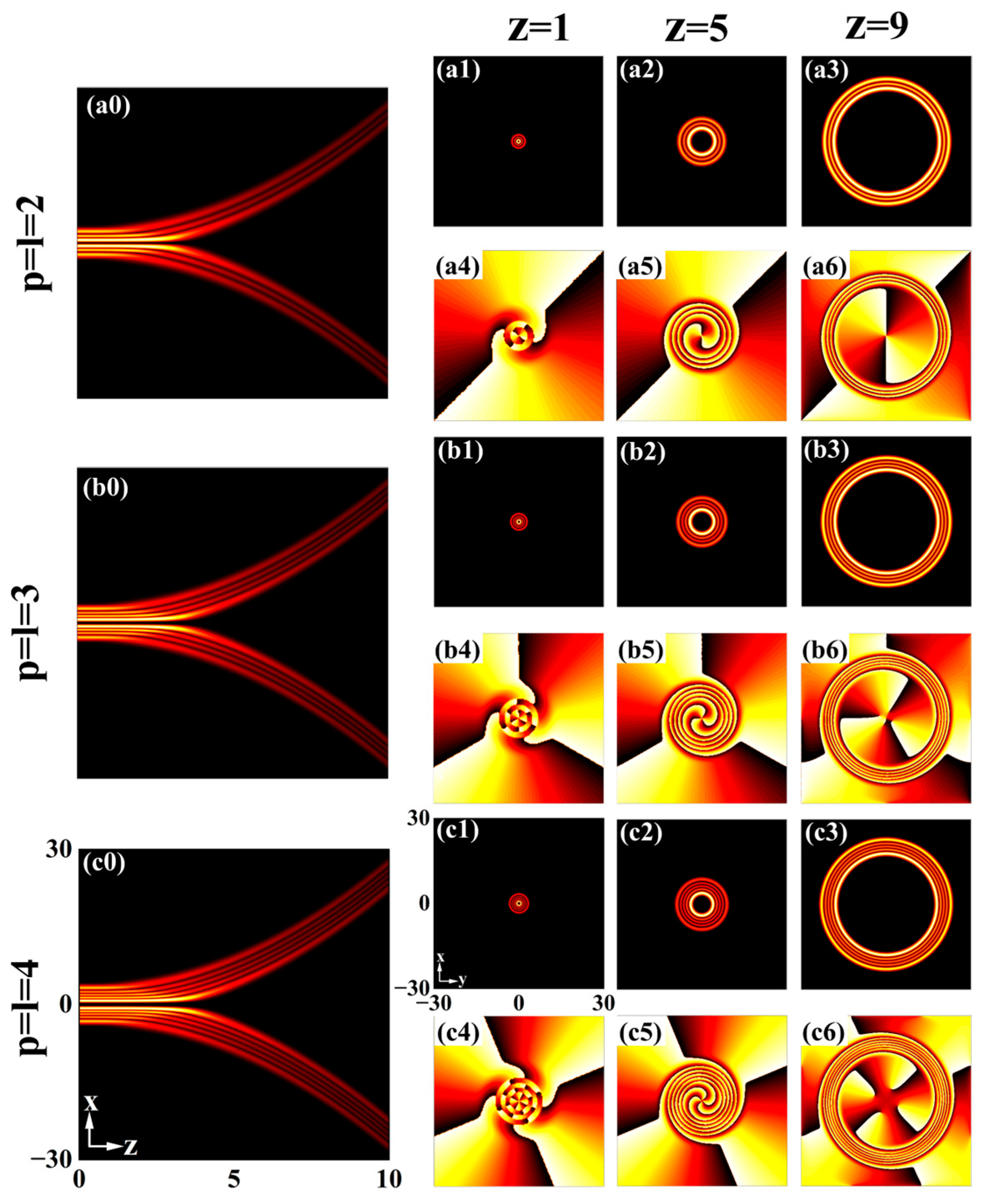
The transmission characteristics of the LG beam under linear modulation are examined in this section. Figure 8 depicts the evolution of the beam with various Lévy indices α under linear modulations. In Figure 8(a0–c0), the energy of the beam accelerates to diffuse after a short propagation distance, with the onset of spreading occurring earlier as α increases. This behavior can be attributed to the linear modulation, which results in a linear rise in diffraction as the transmission distance grows. Moreover, an increase in α further enhances this diffraction. From Figure 8(a1–c3), the spot enlarges significantly as the transmission distance increases, and the diffusion effect intensifies with a higher α . The three-dimensional transport of the beam resembles a “trumpet-like” shape, whose caliber widens as diffraction intensifies.
Figure 9 demonstrates the evolution of the LG beam for several radial and azimuthal indices under the linear modulation when α = 1 . Similarly, the scattering tendency of the beam is not affected by the radial and azimuthal indices, as shown in Figure 9(a0–c0). In Figure 9(a1–c3), the spot size remains essentially constant in the early stage of transmission. Due to the linear growth of the diffraction effect, the spot expands rapidly, forming a circular structure with a large hollow region. The number of rings, given by (p + 1), increases with the radial index. The corresponding phases experience counterclockwise rotation and distortion amplification, with the number of singularities (l) varying as a function of the azimuthal index. The study described above explores three types of modulation individually for controlling the LG beam. A unique transmission shape occurs if two variable coefficient modulations are combined. As an example, under the combined effect of cosine and power function modulation, the LG beam exhibits a large and a small periodic bound state. The expansion and contraction of the beam can also be controlled by varying the power function modulation coefficient.

3.5. With Different Modulations ( α < 1 )

Figure 10 depicts the propagation properties of the LG beam with different Lévy indices ( α < 1 ) under cosine modulation, power function modulation and linear modulation, consecutively. As can be seen in Figure 10(a0–a2), the beam exhibits a periodic evolution under the cosine modulation, and the diffraction effect is enhanced as α increases, leading to an expansion of the transverse amplitude. The magnitude of the energy reduction when the beam defocuses gets larger as α increases in Figure 10(a3). For a power function modulation, the evolution of the beam during propagation tends to be linear when the α is small in Figure 10(b0–b2), while the diffraction effect of the beam grows with increasing α , which delays its stabilization for transmission. From Figure 10(b3), the energy of the beam is more concentrated when α is small and the peak amplitude remains essentially constant. As α increases, the peak amplitude first decreases and then stays unchanged at a certain distance. Figure 10(c0–c2) demonstrates that the beam begins to diffuse after a shorter propagation distance with the linear modulation, with a larger α causing the beam diffusion to appear earlier. The energy of the beam rapidly decays after a short distance focusing in Figure 10(c3). The beam focuses faster as the α increases. This behavior is due to the fact that as the Lévy index rises, the beam energy diffuses outwards and accelerates, which is induced by increased diffraction, which reduces the focal length. A smaller α makes the beam less susceptible to diffraction effects, allowing it to travel further independently before focusing, thus extending the focal length. This is consistent with previous research on FSE [33,34].

4. Conclusions

In this paper, we analyze the propagation characteristics of LG beams in the variable coefficient FSE with various diffraction modulations. In the absence of modulation, the beam expands continuously as it propagates, with its spread speed influenced by the Lévy index. Under the cosine modulation, the beam exhibits cosine oscillations accompanied with periodic inversions, where both the oscillation period and amplitude can be precisely controlled via the Lévy index and modulation frequency. Power function modulation leads to the gradual formation of a stable structure, with the stabilization time dictated by the Lévy index and modulation coefficient. In contrast, linear modulation induces a “trumpet-like” evolution due to the linear growth of the diffraction effect on the beam during transmission, whose caliber is determined via the Lévy index. When α < 1 , the propagation characteristics of beams under various modulations are similar to those observed in the case of α 1 . The results not only enrich the investigation of LG beams in a variable coefficient FSE but also have potential applications in areas such as optical communication and particle manipulation.

Author Contributions

Conceptualization, C.T. and X.H.; formal analysis, M.Z.; investigation, X.H. and Y.L.; data curation, X.H.; writing—original draft preparation, X.H.; writing—review and editing, Y.L., M.Z. and C.T.; project administration, C.T.; funding acquisition, B.Z. and C.T. All authors have read and agreed to the published version of the manuscript.

Funding

This research was supported by the Hunan Provincial Natural Science Foundation of China (Grant Nos. 2022JJ30264, 2024JJ5161).

Institutional Review Board Statement

Not applicable.

Informed Consent Statement

Not applicable.

Data Availability Statement

Data underlying the results are all presented in this paper.

Conflicts of Interest

The authors declare no conflicts of interest.

References

  1. Tian, Y.; Wang, L.; Duan, G.; Yu, L. Multi-trap optical tweezers based on composite vortex beams. Opt. Commun. 2021, 485, 126712. [Google Scholar] [CrossRef]
  2. Avramov-Zamurovic, S.; Watnik, A.T.; Lindle, J.R.; Judd, K.P. Designing laser beams carrying OAM for a high-performance underwater communication system. J. Opt. Soc. Am. A 2020, 37, 876–887. [Google Scholar] [CrossRef] [PubMed]
  3. Ali, R.; Su, W.; Ullah, U.; Muhammad, A.; Rahman, A.U.; Akbar, J.; Usman, M. Amplification of rotary photon drag using Laguerre-Gaussian beam of control field. Opt. Quantum Electron. 2024, 56, 1443. [Google Scholar] [CrossRef]
  4. Peng, B.; Zhong, K.; Li, Z. Influence of topological charge on turbid underwater propagation of Laguerre-Gaussian vortex beams. Acta Opt. Sin. 2017, 37, 50–56. [Google Scholar]
  5. Wang, M.; Yu, W.; Huang, C. Transmission characteristics of underwater Laguerre-Gaussian vortex Beam and its superposition states. Acta Opt. Sin. 2023, 43, 317–325. [Google Scholar]
  6. Zhao, L.; Xu, Y.; Dan, Y. Evolution properties of partially coherent radially polarized Laguerre–Gaussian vortex beams in an anisotropic turbulent atmosphere. Opt. Express 2021, 29, 34986–35002. [Google Scholar] [CrossRef] [PubMed]
  7. Abramochkin, E.G.; Kotlyar, V.V.; Kovalev, A.A.; Stafeev, S.S. Generalized Asymmetric Hermite–Gaussian and Laguerre–Gaussian Beams. Photonics 2023, 10, 606. [Google Scholar] [CrossRef]
  8. Wang, Y.; Bai, L.; Xie, J.; Huang, C.; Guo, L. Radial spectrum spread of Laguerre-Gaussian beam transmission in weak compressible turbulence. Opt. Commun. 2024, 554, 126819. [Google Scholar] [CrossRef]
  9. Badás, M.; Piron, P.; Bouwmeester, J.; Loicq, J. On the optimum far-field irradiance distribution using Laguerre-Gaussian beams for intersatellite free-space optical communications. Opt. Express 2024, 32, 31597–31620. [Google Scholar] [CrossRef] [PubMed]
  10. Wang, X.; Ma, Y.; Yuan, Q.; Chen, W.; Wang, L.; Zhao, S. Properties of focused Laguerre-Gaussian beam propagating in anisotropic ocean turbulence. Chin. Phys. B 2024, 33, 024208. [Google Scholar] [CrossRef]
  11. Zhang, Y.; Lin, Q.; Zhuang, Z.; Lin, F.; Hong, L.; Che, Z.; Zhuo, L.; Li, Y.; Zhang, L.; Zhao, D. Dynamics of dual-orbit rotations of nanoparticles induced by spin–orbit coupling. Nanophotonics 2025. [Google Scholar] [CrossRef]
  12. Zhang, Y.; Zhang, S.; Qi, Y.; Lü, J.-Q.; Liu, Z.; Li, J.; Lin, X.; Lu, Z. On-demand spatial modes and vortex beams from a visible Pr: YLF orbital Poincaré laser with a hybrid pumping scheme. Opt. Express 2025, 33, 1952–1961. [Google Scholar] [CrossRef] [PubMed]
  13. Laskin, N. Fractional quantum mechanics. Phys. Rev. E 2000, 62, 3135–3145. [Google Scholar] [CrossRef] [PubMed]
  14. Zhao, X.; Sun, Z.-Z.; Hao, Z.-P. A fourth-order compact ADI scheme for two-dimensional nonlinear space fractional Schrödinger equation. SIAM J. Sci. Comput. 2014, 36, 2865–2886. [Google Scholar] [CrossRef]
  15. Longhi, S. Fractional Schrödinger equation in optics. Opt. Lett. 2015, 40, 1117–1120. [Google Scholar] [CrossRef] [PubMed]
  16. Zhang, L.; Li, C.; Zhong, H.; Xu, C.; Lei, D.; Li, Y.; Fan, D. Propagation dynamics of super Gaussian beams in fractional Schrödinger equation: From linear to nonlinear regimes. Opt. Express 2016, 24, 14406–14418. [Google Scholar] [CrossRef] [PubMed]
  17. Tan, C.; Liang, Y.; Zou, M.; Lei, T.; Liu, M. The control for multiple kinds of solitons generated in the nonlinear fractional Schrödinger optical system based on Hermite-Gaussian beams. Commun. Nonlinear Sci. Numer. Simul. 2024, 140, 108375. [Google Scholar] [CrossRef]
  18. Zhang, L.; Zhang, X.; Wu, H.; Li, C.; Pierangeli, D.; Gao, Y.; Fan, D. Anomalous interaction of Airy beams in the fractional nonlinear Schrödinger equation. Opt. Express 2019, 27, 27936–27945. [Google Scholar] [CrossRef] [PubMed]
  19. Zhang, L.; He, Z.; Conti, C.; Wang, Z.; Hu, Y.; Lei, D.; Li, Y.; Fan, D. Modulational instability in fractional nonlinear Schrödinger equation. Commun. Nonlinear Sci. Numer. Simul. 2017, 48, 531–540. [Google Scholar] [CrossRef]
  20. He, S.; Malomed, B.A.; Mihalache, D.; Peng, X.; Yu, X.; He, Y.; Deng, D. Propagation dynamics of abruptly autofocusing circular Airy Gaussian vortex beams in the fractional Schrödinger equation. Chaos Solitons Fractals 2021, 142, 110470. [Google Scholar] [CrossRef]
  21. He, S.; Zhou, K.; Malomed, B.A.; Mihalache, D.; Zhang, L.; Tu, J.; Wu, Y.; Zhao, J.; Peng, X.; He, Y.; et al. Airy-Gaussian vortex beams in the fractional nonlinear-Schrödinger medium. J. Opt. Soc. Am. B 2021, 38, 3230–3236. [Google Scholar] [CrossRef]
  22. Wang, J.; Jin, Y.; Gong, X.; Yang, L.; Chen, J.; Xue, P. Generation of random soliton-like beams in a nonlinear fractional Schrödinger equation. Opt. Express 2022, 30, 8199–8211. [Google Scholar] [CrossRef] [PubMed]
  23. Zhou, W.; Liu, A.; Huang, X.; Bai, Y.; Fu, X. Propagation dynamics of Laguerre-Gaussian beams in the fractional Schrödinger equation with noise disturbance. J. Opt. Soc. Am. A 2022, 39, 736–743. [Google Scholar] [CrossRef] [PubMed]
  24. Zhao, S.; Li, J.; Li, T.; Huang, X.; Bai, Y.; Fu, X. Dynamics of Airyprime beams with higher-order spectral phase modulation in the fractional Schrödinger equation. Laser Phys. 2024, 34, 095001. [Google Scholar] [CrossRef]
  25. Tan, C.; Liang, Y.; Zou, M.; Lei, T.; Tang, P.; Liu, M. Propagation dynamics of the Hermite-Gaussian beam in the fractional Schrödinger equation with different potentials. J. Opt. Soc. Am. B 2024, 41, 921–930. [Google Scholar] [CrossRef]
  26. Liu, S.; Zhang, Y.; Malomed, B.A.; Karimi, E. Experimental realisations of the fractional Schrödinger equation in the temporal domain. Nat. Commun. 2023, 14, 222. [Google Scholar] [CrossRef]
  27. Liu, S.; Zhang, Y.; Virally, S.; Karimi, E.; Malomed, B.A.; Seletskiy, D.V. Experimental emulator of pulse dynamics in fractional nonlinear Schrödinger equation. Laser Photonics Rev. 2025, 2401714. [Google Scholar] [CrossRef]
  28. Zang, F.; Wang, Y.; Li, L. Dynamics of Gaussian beam modeled by fractional Schrödinger equation with a variable coefficient. Opt. Express 2018, 26, 23740–23750. [Google Scholar] [CrossRef]
  29. Xin, W.; Song, L.; Li, L. Propagation of Gaussian beam based on two-dimensional fractional Schrödinger equation. Opt. Commun. 2021, 480, 126483. [Google Scholar] [CrossRef]
  30. Li, P.; Wei, Y.; Malomed, B.A.; Mihalache, D. Stabilization of axisymmetric Airy beams by means of diffraction and nonlinearity management in two-dimensional fractional nonlinear Schrödinger equations. Symmetry 2022, 14, 2664. [Google Scholar] [CrossRef]
  31. Tan, C.; Lei, T.; Zou, M.; Liang, Y.; Chen, L.; Tang, P.; Liu, M. Manipulating circular Airy beam dynamics with quadratic phase modulation in fractional systems under some diffraction modulations and potentials. Opt. Express 2024, 32, 25261–25275. [Google Scholar] [CrossRef] [PubMed]
  32. Tan, C.; Liang, Y.; Zou, M.; Lei, T.; Chen, L.; Tang, P.-H.; Liu, M.-W. Controlling Hermite-Gaussian beams dynamics with quadratic phase modulation in fractional systems based on different variable coefficients and potentials. Acta Phys. Sin. 2024, 73, 134205. [Google Scholar] [CrossRef]
  33. Zhang, L.; Zhang, X.; Yu, P.; Ge, X.-L.; Chen, C.; Man, Z.; Deng, D. Space–time dispersive symmetric Pearcey-Pearcey wave packets in the fractional Schrödinger equation. Opt. Lett. 2024, 49, 4681–4684. [Google Scholar] [CrossRef]
  34. He, S.; Peng, X.; He, Y.; Shan, C.; Deng, D. Propagation dynamics of the second-order chirped circular Pearcey Gaussian vortex beam in the fractional nonlinear Schrödinger equation. Chaos Solitons Fractals 2024, 189, 115734. [Google Scholar] [CrossRef]
Figure 1. (a0c0) Evolution of LG beams for different Lévy indices α , (a1c1) intensity distribution at z = 7 in the x - y plane, (d) envelope corresponding to (a0c0).
Photonics 12 00163 g001
Figure 2. (a0c0) Evolution of LG beams for different Lévy indices α under cosine modulation, Ω = 0.1 . (a1a3,b1b3,c1c3) The corresponding intensity distribution to (a0c0). (a4a6,b4b6,c4c6) The corresponding phase to (a0c0).
Photonics 12 00163 g002
Figure 3. (a0c0) Evolution of LG beams for different modulation frequencies Ω ( α = 1 ). (a1c1) The corresponding three-dimensional isosurface plots to (a0c0). (d) The beam width and (e) the envelope vary with transmission distance z, respectively.
Photonics 12 00163 g003
Figure 4. (a0c0) Evolution of LG beams for different radial and azimuthal indices, Ω = 0.1 , α = 1 . (a1c3) The corresponding intensity and phase distribution to (a0c0).
Photonics 12 00163 g004
Figure 5. (a0c0) Evolution of LG beams for different Lévy indices α under power function modulation, k = 1 . (a1c1) Intensity distribution at z = 7 in x - y plane. (a2c2) The corresponding three-dimensional isosurface plots to (a0c0). (d0) The beam width and (d1) the envelope vary with transmission distance z, respectively.
Photonics 12 00163 g005
Figure 6. (a0c0) Evolution of LG beams for different modulation coefficients k , α = 1 . (a1c3) The corresponding intensity and phase distribution to (a0c0).
Photonics 12 00163 g006
Figure 7. (a0c0) Evolution of LG beams for different radial and azimuthal indices, k = 1 , α = 1 . (a1c3) The corresponding intensity and phase distribution to (a0c0).
Photonics 12 00163 g007
Figure 8. (a0c0) Evolution of LG beams for different Lévy indices α under linear modulation. (a1c3) The corresponding intensity and phase distribution to (a0c0). (d0d2) The corresponding three-dimensional isosurface plots to (a0c0).
Photonics 12 00163 g008
Figure 9. (a0c0) Evolution of LG beams for different radial and azimuthal indices under the linear modulation when α = 1 . (a1a3,b1b3,c1c3) The corresponding intensity distribution to (a0c0). (a4a6,b4b6,c4c6) The corresponding phase to (a0c0).
Photonics 12 00163 g009
Figure 10. (a0c2) Evolution of LG beam for different Lévy indices α under various modulations when α < 1 . (a3c3) The envelope varies with transmission distance z.
Photonics 12 00163 g010
Disclaimer/Publisher’s Note: The statements, opinions and data contained in all publications are solely those of the individual author(s) and contributor(s) and not of MDPI and/or the editor(s). MDPI and/or the editor(s) disclaim responsibility for any injury to people or property resulting from any ideas, methods, instructions or products referred to in the content.

