Abstract
The mid-wave infrared (MWIR) spectral range can provide a larger bandwidth for optical sensing and communication when the near-infrared band becomes congested. This range of thermal signatures can provide more information for digital imaging and object recognition, which can be unraveled from polarization-sensitive detection by integrating the metasurface of the subwavelength-scale structured interface to control light–matter interactions. To enforce the metasurface-enabled simultaneous detection and parallel analysis of polarization states in a compact footprint for 4-micron wavelength, we designed a high-contrast germanium metasurface with an axially asymmetric triangular nanoantenna with a height 0.525 times the working wavelength. First, we optimized linear polarization separation of a 52-degree angle with about 50% transmission efficiency, holding the meta-element aspect ratio within the 3.5–1.67 range. The transmission modulation in terms of periodicity and lattice resonance for the phase-gradient high-contrast dielectric metasurface in correlation with the scattering cross-section for both 1D and 2D cases has been discussed for reducing the aspect ratio to overcome the nanofabrication challenge. Furthermore, by employing the geometric phase, we achieved 40% and 60% transmission contrasts for the linear and circular polarization states, respectively, and reconstructed the Stokes vectors and output polarization states. Without any spatial multiplexing, this single metasurface unit cell can perform well in the division of focal plane Stokes thermal imaging, with an almost 10-degree field of view, and it has an excellent refractive index and height tolerance for nanofabrication.
1. Introduction
Polarization is an inherent property of light where the information remains encoded in the Poincaré space and can be decoded by knowing the state of polarization (SOP) of the light. When light is transmitted or reflected by any structure, the propagating SOP with respect to the incident SOP can provide a lot of information if we can detect it, constituting a rich field of polarimetry. The polarization states of light give the hidden features of an object, like surface pressure and orientation, hidden layers, and transparency, to ensure better object recognition.
The following three main detection methods exist: division of amplitude, division of aperture, and division of focal planes [1]. There are eight to four-pixel hybrid image sensors for maneuvering polarization filtering with a focal plane array (FPA) that operates without a metasurface [2]. Polarization-sensitive imaging technologies have been around for several decades but are still limited by mechanical switching and bulky optics. Previously, the division of aperture was utilized for MWIR polarimetric imaging [3]. However, metasurface-enabled on-chip polarimetry is the technological trend that is now used for compact imaging devices.
The increasing applications of computational image analysis, pattern recognition, machine vision, Lidar, and remote sensing largely depend on polarization-selective imaging for visualizing edges and corners for better image contrast. Various technologies have been applied to MWIR polarization image sensors, such as high-speed rotating polarization analyzers, where the image of different polarized angles is captured by swiftly rotating the polarizer or analyzer [4,5]. For a scenario of a rapidly changing object’s features or a target’s speed, we need to obtain the Stokes parameters simultaneously without any time delay. So, the recently developed technique of integrating a compact optical metasurface for the division of focal plane polarization-sensitive imaging needs further investigation to be implemented in MWIR thermal sensing [6,7,8,9,10]. Though the infrared polarized imaging technique is utilized for various commercial and defense applications, it is still very expensive.
In recent years, the subwavelength-scale artificially structured surface, called a metasurface, has been proven to be a reliable technology that can unravel this phenomenon in an efficient way [7,11,12,13,14,15,16,17]. The dielectric metasurface diffraction grating structure has been utilized for polarimetry, polarization converters, holography, optical sensing, and many other applications. Optimized metasurface device structures are already in commercial application in the visible and near-infrared range; very few studies have reported the metasurface design for the polarimetric application in the MWIR range, which needs more attention [18,19,20,21,22,23]. The work presented by Chen et al. is excellent, presenting simultaneous wavelength multiplexing polarimetry, which serves as a cascade of a parallel filter, polarizer, and waveplate for the 3–4.5 μm range, overcoming many challenges. However, the limitation of the design is the detection of only one set of orthogonal polarization states at a particular wavelength and with the nanoantenna of a high aspect ratio of ~30 [23]. Yan et al. proposed the division of a focal plane metasurface imaging mask with a silicon metasurface using a polarization-controlled phase modulation technique. However, it is intended for a long-wave infrared (LWIR) 10.6 μm wavelength [22]. Reducing the crosstalk, Zhang et al. demonstrated a 9–12 μm LWIR achromatic full-Stokes imaging metalens, but it had a high aspect ratio of 10:1 for the Si meta-element and a shared aperture designated for the six detectors [24]. Yin et al. showed that a Si substrate, has better transmission efficiency as compared to a SiO2 substrate, but it is operational in the near-infrared range [25]. The phase change material of Ge2Sb2Te5 (GST) allows for more tunability, owing to its inherited amorphous-to-crystalline transition property with polarization switching, but this is useful for the LWIR range [26]. To investigate the polarization-controlled and achromatically on-axis focused optical vortex beams from 3.5 to 5 μm, Ou et al. came up with all-Si metasurface optimization [18]. They showed promising functionality, being capable of even switching the topological charge. Yet, the high aspect ratio and the use of only two orthogonal polarization states pose a limitations for on-chip polarimetry.
The variety of metasurfaces consists of staking geometry, and layered structures are evolving; yet, they do not address the challenge of nanofabrication. With a vertically stacked photodiode, nanowire polarizer filters have been reported [27], and hybrid image sensors for detecting angular light, intensity, and polarization have been presented [2]. However, very complicated fabrication steps are required, which cannot be carried out with single-step lithography. We propose a simple Ge metasurface feasible by a single step nanofabrication for Stokes imaging, optimized for the 4 μm wavelength, which is a highly transparent atmospheric window.
2. Design Principle and Simulation
2.1. Material Library, Design Parameter, and Simulation Methodology
The present work uses the axially asymmetric triangular meta-element of Germanium of a refractive index nGe = 4.025 at 4 μm wavelength for the metasurface design with the finite difference time domain (FDTD) simulation package from Ansys-Lumerical Inc. (Canonsburg, PA, USA). The low refractive index substrate CaF2 has been used for the transmission mode design, which is suitable for this wavelength and for integrating the metasurface with an uncooled PbSe focal plane array (FPA) [28]. First, gradually increasing the height for some triangular-shape Ge meta-element, we check the full phase coverage for a periodicity of 2500 nm. Since the λ0/nGe = 994, as shown in Figure 1 (top), we present the transmission and phase profile with the height increment of the triangular meta-element of a length and base of ~994 nm. We observe that when the height reaches above 2100 nm, we achieve a full propagation phase coverage, with good transmission marked by the black circle. Then, for an estimated fixed height of 2150 nm, we vary the length and base of the triangular nanoantenna, holding 994 nm as the median value, as shown in Figure 1, along with the phase and transmission library for the single meta-element. A periodic boundary has been implemented on the sides and PML boundary to the light propagation direction from the substrate towards the nanoantenna, placing the DFT monitor several wavelengths away. We used all PML boundaries with a total-field scattered-field (TFSF) source for the scattering cross-section.
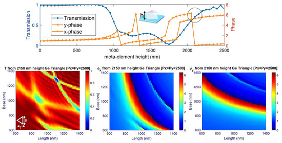
Figure 1.
Transmission and phase variation with the height increment of the Ge triangular nanoantenna of a length and base of ~994 nm (top). Transmission and phase library for the 2150 nm height Ge triangular nanoantenna (bottom).
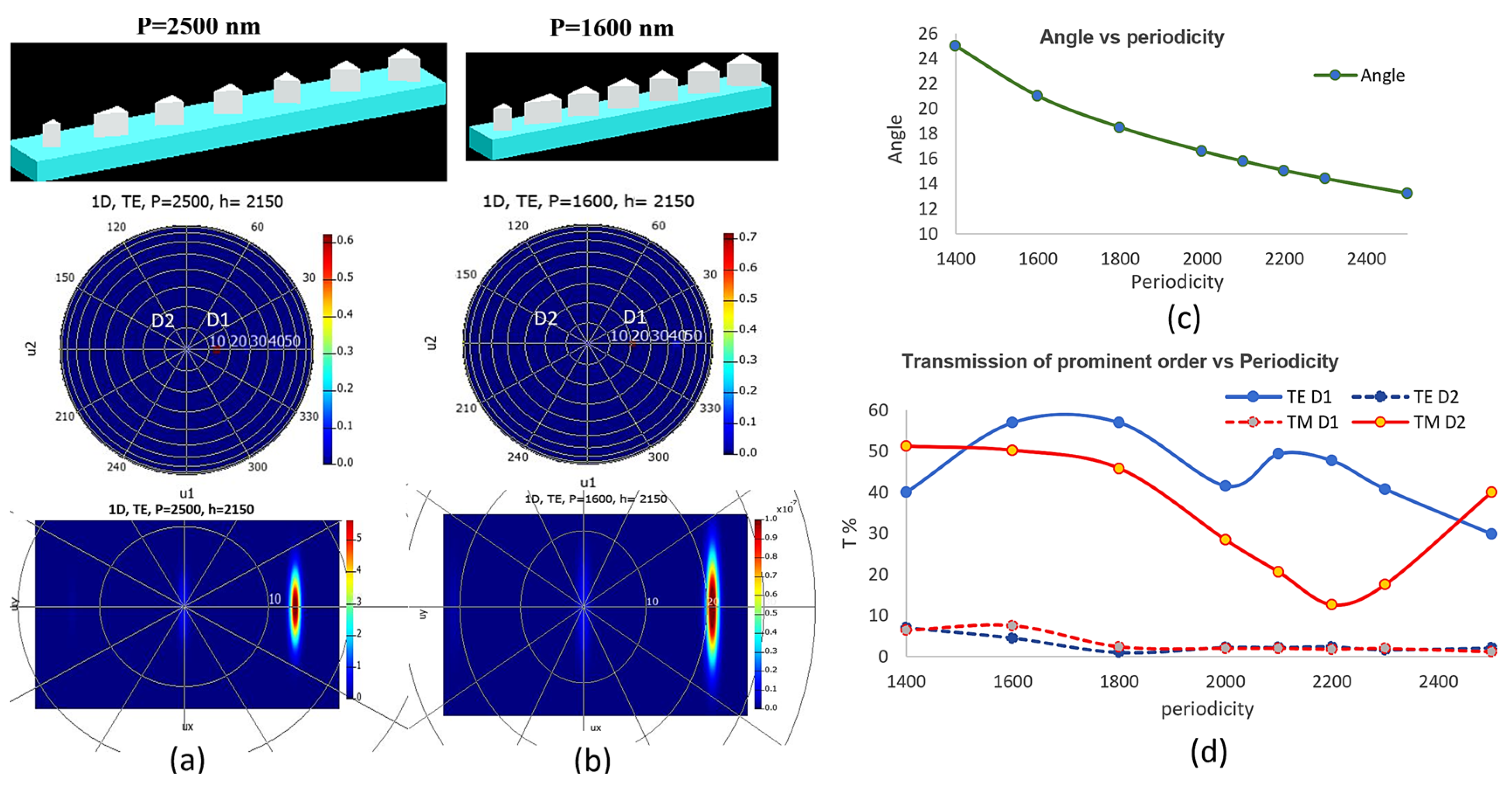
Unlike symmetric rectangular meta-elements, the triangular shape accumulates somewhat different φx and φy with an increase in height. It takes a propagation length ≥2λ inside the meta-element for sufficient propagation phase control. The rectangular meta-element can give more phase control for the same height, lateral dimension, and periodicity, but the triangular meta-element gives better transmission [29]. The phase (φ), and transmission (T) library are presented in Figure 1, which shows some phase discontinuity with anti-crossing transmission behaviors for some spatial dimensions. For this type of high-contrast dielectric structure, resonant absorption decreases the transmission, but for the triangular geometry, the resonance loss is mitigated. Within this element dimension, 2π phase control is difficult with the height reduction in the nanoantenna, as indicated in Figure 1. So, Figure 2a shows the selection of the appropriate elements for the 2π propagation phase gradient. A 2150 nm height 1-dimensional (1D) metasurface gives a maximum of about 60% transmission to the prominent order, whereas a 2750 nm height design can give 78%. Yet, for practical concerns regarding nanofabrication, we aim to reduce the aspect ratio more, going down to a height of 2150 nm because increasing the lateral dimensions is limited by the periodicity.

Figure 2.
(a) 1D metasurface design for P = 2500 nm and the transmission efficiency at the detector position. (b) Same for P = 1600 nm. The corresponding far-field projection is shown at the bottom. (c) Periodicity vs. beam deflection angle at the prominent order. (d) Effect of varying periodicity on the transmission for the 2D LP separation design.
2.2. Lattice Resonance to Enhance Transmission
To overcome the transmission loss with a reduction in height, we implement the strategy of an interacting nanoantenna when (nsubstrate × periodicity)/wavelength <1 holds [29,30,31]. In this strategy, we utilize the lattice resonance to boost transmission by reducing the periodicity. Figure 2a,b compares the transmission for the same unit cell element, where we construct the 7 × 1 element 1D metasurface.
From the linear polarization (LP) separation design, we can see from Figure 2d that the transmission efficiency is highest around the periodicity Px = Py = 1600 nm, for both prominent transmission orders at the two LP separation order positions, D1 and D2. Here, by Px = Py, we mean the periodicity of the single-element unit cell. So, for the normalized lattice constant Px/λ0 = Py/λ0 = 0.625 to 0.35 ratios, the best transmission comes when Px = Py = 0.4 λ0. However, we can say that the propagation phase correlation between the meta-elements in this range remains intact. Although the generalized Snell law explains the phase gradient metasurface, which has served its purpose for decades, its effect on the scattering cross-section is not discussed much. As shown in Figure 3, we investigate the scattering cross-section for the phase gradient metasurface grating (PGMG) for both TE and TM incidence, and we compare the total transmission efficiency for the 2D metasurface.

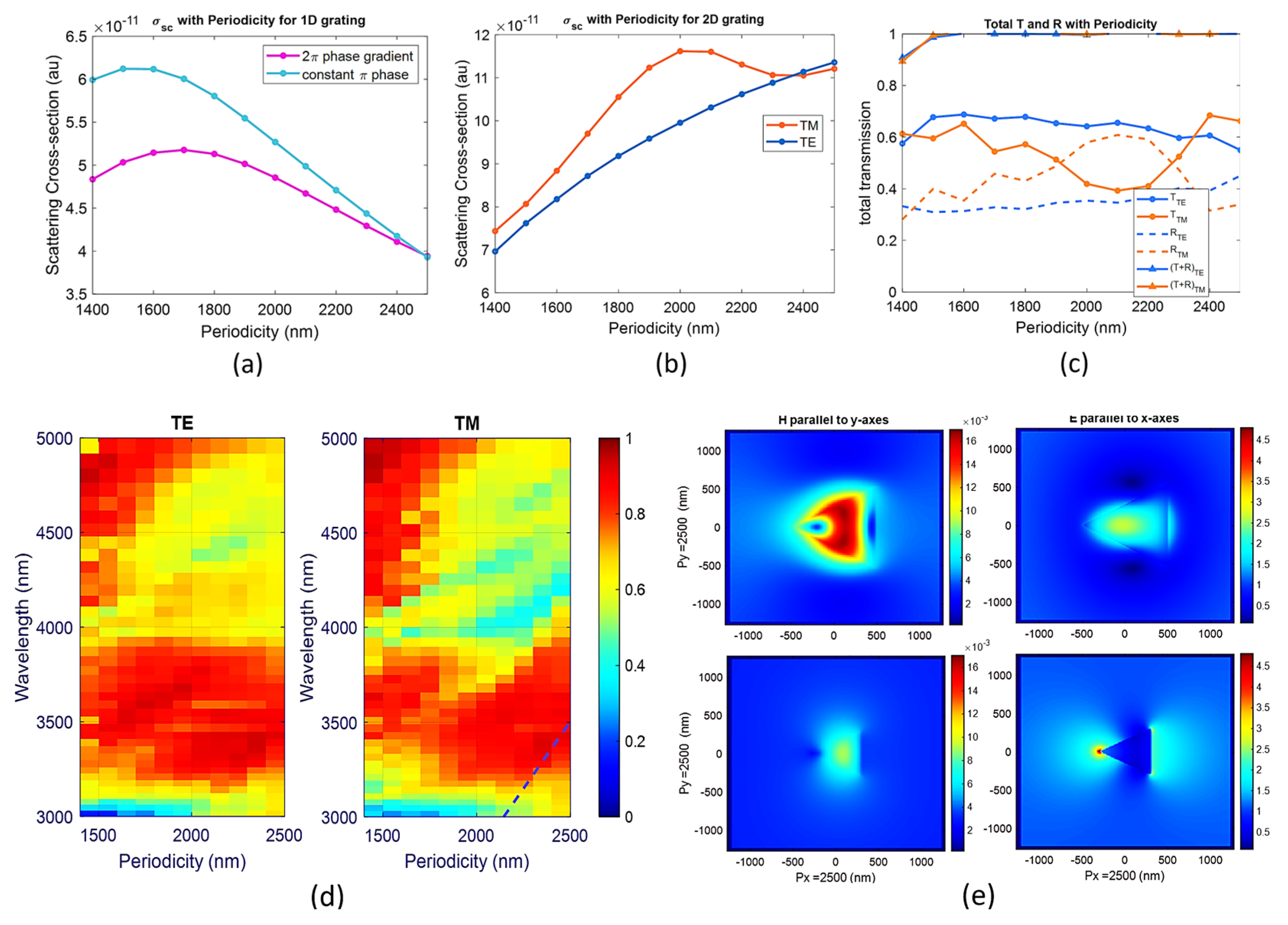
Figure 3.
(a) Scattering cross-section from 1D grating, with and without phase gradient, with periodicity at 4 µm wavelength for TM incidence. (b) Scattering cross-section from 2D grating at a 4 µm wavelength with periodicity. (c) Total T and R from the same 2D grating with periodicity. (d) Spectral response of the total T from the same 2D grating from a 3 µm to 5 µm wavelength with periodicity. (e) The difference in the E- and H-field enhancement and the radiation pattern from smallest size (bottom row) to biggest size (upper row) Ge-triangle nanoantenna, with a 2150 nm height for the same periodicity.
The scattering cross-section from the 1D metasurface when the element of the same height is arranged in a 2π propagation phase gradient (PPG) along the x-axis called PGMG (magenta line). When the element of the same height is placed at a constant π phase along the x-axis, it is called the constant phase (CPMG) (cyan line), with varying periodicity for TM incidence, as presented in Figure 3a. Though around Px/λ0 = Py/λ0 = 0.625, both scattering cross-sections coincide, by decreasing Px = Py, the scattering cross-section increases for both the PGMG and CPMG when the normal incident light has the E-field parallel to the direction of the PPG. Still, for the 1D metasurface, the trend of the difference in scattering cross-section (ΔσSC = σSC, PGMG − σsc, CPMG) has a linear correlation with periodicity.
As we look at the 2D-PGPM of Figure 3b, we see that by decreasing Px = Py, the scattering cross-section decreases with a gradual increase around 0.5λ0–0.55λ0 for the PGMG when the normal incident light has the E-field parallel to the direction of the PPG. Here, we are only interested in the TM or E-field parallel to the direction of the PPG case because, in the 2D metasurface design, the PPG has been assigned oppositely along the x-axis for x- and y-polarized light. So, TM incidence is affected the most due to the surface lattice resonances (SLR). We can see in Figure 3c that with a decrease in periodicity, the total transmission increases, and reflection decreases for TE incidence, but there is no smooth relation for TM incidence. For the negligible absorption of Ge, the scattering conveys the extinction. From the Kerker condition, we know that forward or backward scattering can be tuned by in-phase and out-of-phase electric dipole (ED) and magnetic (MD) moments, respectively, among this type of subwavelength meta-elements [32,33]. The loss in the total transmission, equivalent to around 0.5λ0–0.55λ0 periodicity, shown in Figure 3c, can be explained by the increase in scattering TM incidence, as seen in Figure 3b. Additionally, T + R < 1, for the Px = Py = 0.35λ0, which indicates the lower limit of the dipole approximation has been crossed when Px = Py < 1500 nm [34].
Looking at the spectral response of the T from the 2D metasurface in Figure 3d, we see that TM incidence suffers a T loss above the Rayleigh anomaly indicated by the black dashed line. For a single meta-element, the σsc remains constant with the change in the periodicity. So, the variation of σsc, CPMG, even for the simple seven same meta-element arrangement shown in Figure 3a, indicates the presence of lattice resonance. The different size of the meta-element used for creating PGMG causes a decrease in σsc, PGMG because the different radiative coupling strengths may add up destructively. The ability of the high-contrast dielectric meta-element to generate both ED and MD resonance is an advantage over the plasmonic one [35,36]. For example, for a single particle under TM incidence (E along x-axes), the enhancement of the E-field (right side) and H-field (left side), and the radiation pattern from the smallest size (bottom row) to the biggest size (upper row) is shown in Figure 3e. For the same periodicity, in the case of the bigger-sized triangular meta-element, the E-field resonates mostly within its volume. It enhances the H-field more than the smaller-sized one. In summary, we can say that for the 2D-PGMG, decreasing periodicity decreases scattering and tunes the ED and MD resonances in phase to better overcome reflection (Figure 3b,c), increasing the transmission to the prominent order (Figure 2d).
As our interest is in a fixed wavelength, we are not focusing on the wavelength shift in ED and MD resonances due to meta-element size and periodicity. Also, due to the variety of the size parameters and asymmetry of the geometry of our triangular meta-element, the sharp ED and MD resonant pattern is not visible due to different types of coupling strengths at different lattice points [36]. However, by choosing a periodicity smaller than 2000 nm for assigning the PPG at a 4 µm wavelength, we avoid a particular type of lattice resonance, which has a wavelength longer than the period [36,37] scenario, where power goes to the guided mode or perpendicular evanescent order. This could be the subject of a future study. In this step, we decide the periodicity will be 1600 nm. So, from the same element of T and φ for the periodicity = 1.16 × h library, we move to a new design with periodicity = 0.74 × h, which increases the transmission from 40% to 50.2% for TM (x-polarized) incidence and from 29.8% to 57% for TE (y-polarized) incidence, as shown in Figure 2d. Another benefit, as we can see in Figure 2c, is the increase in angular separation of the deflected beam from 13° to 21°, which follows the PPG metasurface rule of phase profile φ and beam deflection angle θ = arcsin[φ/(2πPx/λ)], as controlled by the generalized Snell law of anomalous deflection [38,39].
2.3. Circular Polarization (CP) Control with Geometric Phase
Although we found the subwavelength scale axially asymmetric nanostructure does not affect the propagation phase because of the lack of rotational symmetry, it hindered the geometric phase, which is supposed to follow the Pancharatnam–Berry (PB) phase rule [40,41]. The PB phase implementation of the 1D structure has been carried out as convolution with a linear increment of phase. Ideally, the PB phase gives a 2θ addition in phase for a θ physical rotation. The transmission modulation of the incident circular polarized light can be performed with the Jones matrix by the operation of the rotation matrix R(θ), as presented in Equation (1), which is as follows [7,42,43]:
where tx and ty are the complex transmittance values of light, while the incident light is polarized towards the x- and y-axes, respectively, when the meta-element has zero rotation. and are the Jones vectors of the left and right circular polarized light. The electric field of the left and right circularly polarized light is given by multiplying with the Jones vector of the LCP and RCP states, as follows:
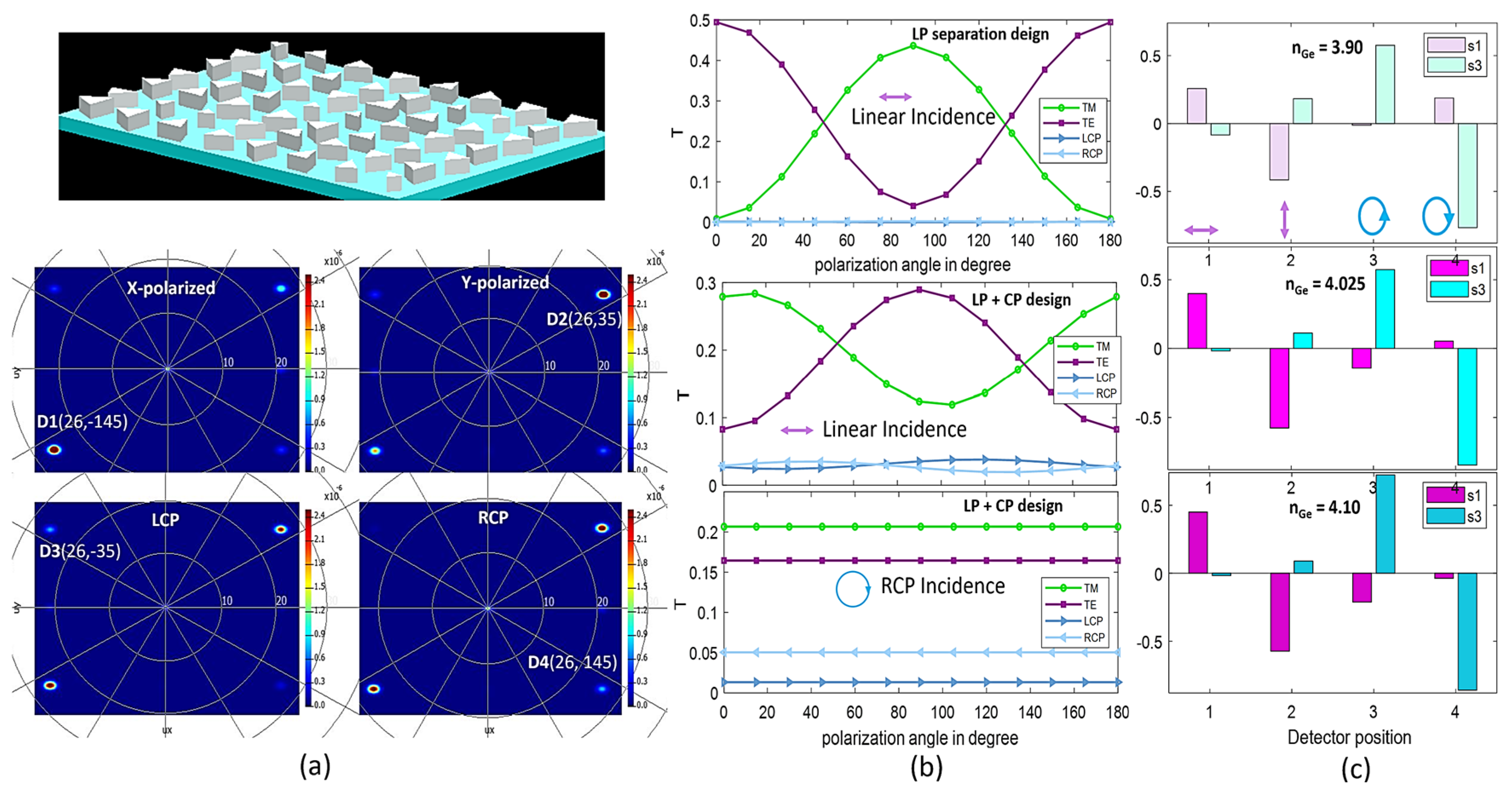
In Equations (3) and (4), the 1st term conveys the transmitted wave with the same helicity as the incident, and the 2nd term conveys the opposite helicity with a phase addition. This general PB phase rule indicates that if the metasurface element cannot provide a phase of at least a π/4 phase retardation, then the element will not be able to control the total phase range [44]. When we reduce the periodicity, the length/periodicity ratio increases. Consequently, the phase is locked in specific angular rotations of the triangular meta-element, as we can see in Reference [45]. We need to increase the Py to reduce L/Py from 0.79 to 0.63. So, we obtain a smooth phase change by increasing only Py from 1600 nm to 2000 nm, keeping Px fixed at 1600 nm since we employed the PB phase towards the y-axes only. Hence, in our final metasurface LP+CP separation design, as presented in Figure 4a, we implement Px = 1600 nm and Py = 2000 nm to preserve the propagation and geometric phases folding orthogonally to each other.
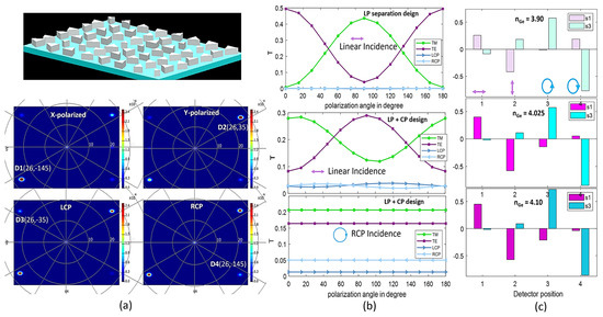
Figure 4.
(a) Schematic of the metasurface and the far-field angular projection for both LP and CP incidence. (b) Transmission efficiency from the designated order position for polarization rotation with LP and CP incidence. (c) Calculated Stokes parameter for the different Ge refractive index.
3. Simulation Results and Discussion
To incorporate LP and CP detection from the same metasurface to the different pixel positions of the detector, we finally came to a design as shown in Figure 4a. The LP detector positions are D1(ɵ,ϕ) = (26°, −145°) and D2(ɵ,ϕ) = (26°, 35°), and the CP detector positions are D3(ɵ,ϕ) = (26°, −35°) and D4(ɵ,ϕ) = (26°, 145°), as we can see in the far-field projection in Figure 4a. So, the final design can measure arbitrary LP and CP states simultaneously. The calculated Stokes parameter is shown in Figure 4a,c, and it is derived by using the following Stokes parameter calculation. The Jones vector representation of the E-field components is as follows [40,46]:
where E0x, E0y, φx, and φy are the orthogonal amplitudes and phases, respectively. When the phase difference between the Ex and Ey is δ, we can express the fraction of polarized and unpolarized light as the state of the polarization (SOP) using the matrix form for the four Stokes parameters from Equation (6), as follows [6,7,9,46,47]:
Unlike the randomly distributed unpolarized scalar light field, the polarized light field is a vector [47]. In optical frequency, we can obtain the measurable parameter intensity only. S0 is the total intensity, S1 indicates the difference in the intensity components Ix and Iy, S2 indicates the difference in the intensity components IL45 and IL−45, and S3 indicates the difference in the intensity of component IRCP and ILCP. We can see all these intensities on different order spots from the far-field view in the FDTD simulation from this Ge metasurface of this schematic in Figure 4a. In the detector plane measuring the light intensity at the four different diffraction order pixel positions for TM, TE, LCP, and RCP incidence separately, we can find the middle Stokes parameter, as shown in Figure 4c. As a Ge-grown technique for achieving a homogeneous refractive index for thick film is still under investigation and almost no n, k measured value was reported with the experimental measurement after Ge deposition at 4 µm wavelength, we check the tolerance of nGe from 3.9 to 4.1 to see if the Stokes parameter remains in the range. This design works well for this nGe range, as shown in Figure 4c. It also has a height tolerance from 2100 to 2200 nm, with both CaF2 and Al2O3 substrates for the 4 µm working wavelength, which we checked by the Stokes parameter. The Stokes parameters are basically the output intensity contrasts for the orthogonal polarization states. For convenience, the transmission for the design update from LP separation and LP+CP separation, for both LP and CP incidence, is also shown in Figure 4b.
The role of the polarization-sensitive camera is to capture the Stokes vector from each point of an image. So, all independent polarization state imaging is required to form the Stokes vector. From the sensing perspective, the dedicated pixel should record the intensity of the independent polarization state [6,7]. We want our metasurface to separate the most prominent transmission order projected, based on the polarization states of the incident light, to different pixel positions on the sensor for the intensity vector.
We directly reconstruct the Stokes vector from the simulation by using Equation (6). In the experimental situation, there is a linear correlation between the Stokes vector and the intensity with instrument matrix A, which comes from the experimental setup used for the calibration of the polarization states of the incident beam. Knowing the calibration of the pure polarization states with our metasurface, we can calculate the Stokes vector by the following:
After obtaining the S values at each pixel, we can find the necessary parameters for polarization imaging; one is the degree of polarization (DOP), and the other is the physical orientation angle ψ of the polarization ellipse, as follows:
The image formed with the total intensity is a regular camera image. However, the image formed with the information of ψ and DOP can reveal more contrast, edge features, and internal stress as it accounts for the orientation of the electric field in the Poincaré space. We want to perform single metasurface-aided division of focal plane imaging, where the aperture stop plays a more important role than the spatial phase profile of the detector plane [7,9,41,48,49].
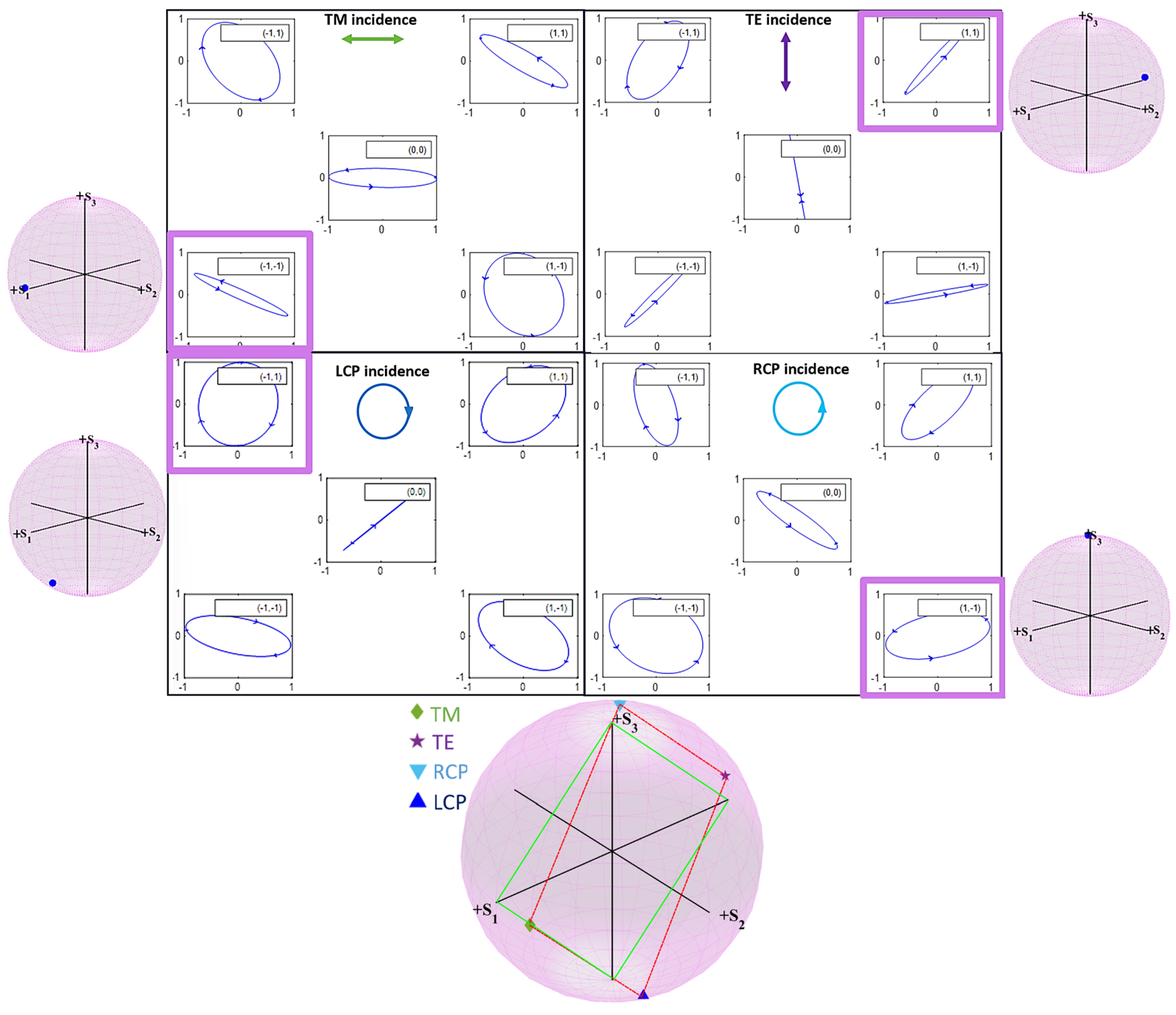
In the detector plane, by measuring the intensity of light on the different diffraction order pixel positions, we can reconstruct the Stokes parameter, which has been presented from a far-field view in the simulation in Figure 5. Here, the four boxes represent the shape of the output polarization ellipse when one of the four incidence polarization states is projected by the metasurface at the detector plane. We also show the (0, 0) order position that is used for convenience, achieving negligible intensity for our metasurface. The pink boxed order position is the prominent order reserved to analyze the Stokes parameter. Outside the box, we see the reconstructed Stokes vector in the Poincaré sphere for the designated order position. Although this metasurface does not work for all six input polarization separations because the efficiency and intensity contrast are very low for L + 45 and L − 45 states, in the calculation, we consider all the intensities from the six polarization states. Finally, the bottom Poincaré sphere shows the figure of merit of this metasurface, where we use the four maximally different input polarization states and reconstruct the Stokes vector from all the order positions by simulated intensity. The deviation in the metasurface analyzer polarization states by the simulated intensity could be due to the loss of the intensity to different unwanted order states other than the four prominent orders.
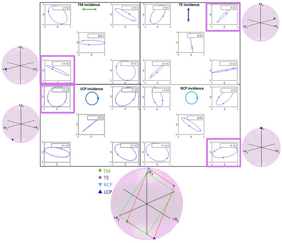
Figure 5.
Simultaneous polarization ellipse at the four designated polarization order positions for a particular incidence polarization. Prominent order for TM at (−1, −1), TE at (1, 1), RCP at (1, −1), LCP at (−1, 1) position, and all (0, 0) order position. Outside the Poincaré spheres are the reconstructed Stokes vectors for those prominent orders outlined with pink. The bottom Poincaré sphere is the metasurface-analyzed Stokes vector from all the order positions. The green square represents the maximally different polarization states, and the dotted red line shows the polarimetric reconstruction of the metasurface analyzer’s polarization states based on the simulated intensity.
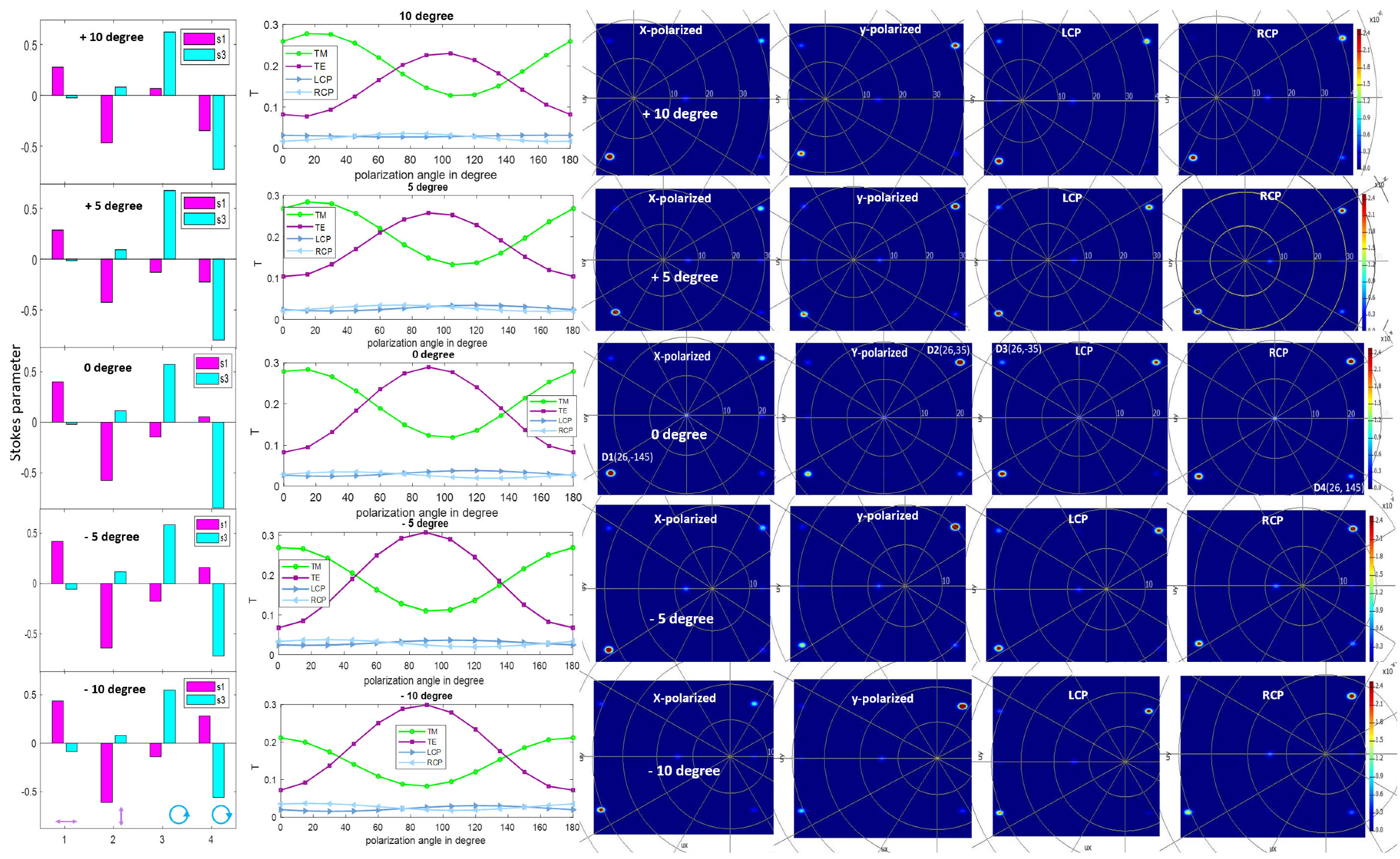
For non-paraxial incidence, the performance remains almost the same for the 5° tilted incident angles, with less than 10% transmission deviation, as presented in Figure 6. Still, the angular position of the beam changes by about 7°, as we can see in Figure 6, in the far-field projection. For a 10° tilted incident angle, the angular position changes to about 14.5°, so there is an overall 14° angular shift for the ±5° field-of-view and a 29° angular shift for the 10° field-of-view. From the left side, we see the variation in the Stokes parameter is within a tolerable range for the 4-detector position within a ±5° non-paraxial incidence for this metasurface.
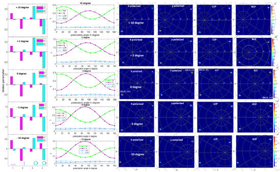
Figure 6.
Stokes parameter (left), transmission (middle), and far-field angular projection (right) from 10° (top) to −10° (bottom) tilted incident polarization with 0–180° polarization rotation. The designated polarization states used for the detection are indicated underneath as the detector number for the left picture.
4. Conclusions
Using an asymmetric Ge meta-element, we optimized the polarimetric metasurface design for 4 μm wavelength full Stokes imaging by significantly reducing the aspect ratio of the nanoantenna for a structurally robust design for a single-step E-beam lithography fabrication technique. This provides higher transmission while overcoming the challenges of insufficient phase control. Along the way, we have investigated the effect of lattice resonance in terms of periodicity for the interactive meta-element for high-contrast dielectric phase operator metasurface. Adjusting the propagation and geometric phases orthogonally, we proved that the single-unit cell metasurface works for polarimetric detection by reconstructing the full Stokes parameter from the simulation. Hence, they work simultaneously to detect and analyze any arbitrary polarization state without a shared aperture. The optimized Stokes parameter for the refractive index and height tolerances, accommodating for slightly angled non-paraxial rays, reported a feasible design which, when integrated with the uncooled FPA, can be a chip-scale low-cost, polarization-sensitive thermal imaging device that is still not commercially available. This technology may open doors for MWIR long-range surveillance, land mine detection, infrared homing devices, and sensors with a compact on-chip polarimetric detection technology.
Funding
This research received no external funding.
Institutional Review Board Statement
Not applicable.
Data Availability Statement
No data were generated or analyzed in the presented research.
Conflicts of Interest
The author declares no conflicts of interest.
References
- Tyo, J.S.; Goldstein, D.L.; Chenault, D.B.; Shaw, J.A. Review of passive imaging polarimetry for remote sensing applications. Appl. Opt. 2006, 45, 5453–5469. [Google Scholar] [CrossRef]
- Carvalho, F.F.; Cruz, C.A.d.M.; Marques, G.C.; Damasceno, K.M.C. Angular Light, Polarization and Stokes Parameters Information in a Hybrid Image Sensor with Division of Focal Plane. Sensors 2020, 20, 3391. [Google Scholar] [CrossRef]
- Pezzaniti, J.L.; Chenault, D.B. A division of aperture MWIR imaging polarimeter. In Polarization Science and Remote Sensing II, Proceedings of the Spie, San Diego, CA, USA, 2–4 August 2005; SPIE: Bellingham, WA, USA, 2005; Volume 5888. [Google Scholar]
- Wu, X.; Huang, H.S.; Peters, K.; Wu, X.; Pankow, M.; Huang, H.S.; Peters, K. High-speed polarization imaging of dynamic collagen fiber realignment in tendon-to-bone insertion region fiber realignment in tendon-to-bone insertion region. J. Biomed Opt. 2018, 23, 1–11. [Google Scholar]
- Harchanko, J.S.; Pezzaniti, L.; Chenault, D.; Eades, G. Comparing a MWIR and LWIR polarimetric imager for surface swimmer detection. In Polarization: Measurement, Analysis, and Remote Sensing VIII, Proceedings of the Spie, 16–20 May 2008; SPIE: Bellingham, WA, USA, 2008; Volume 6945, pp. 194–204. [Google Scholar]
- Ei, S.H.W.; Ang, Z.H.Y. Design of ultracompact polarimeters based on dielectric metasurfaces. Opt. Lett. 2017, 42, 1580–1583. [Google Scholar]
- Rubin, N.A.; D’aversa, G.; Chevalier, P.; Shi, Z.; Chen, W.T.; Capasso, F. Matrix Fourier optics enables a compact full-Stokes polarization camera. Science 2019, 365, eaax1839. [Google Scholar] [CrossRef]
- Zaidi, A.; Rubin, N.A.; Meretska, M.L.; Li, L.W.; Dorrah, A.H.; Park, J.-S.; Capasso, F. Metasurface-enabled single-shot and complete Mueller matrix imaging. Nat. Photonics 2024, 18, 704–712. [Google Scholar] [CrossRef]
- Rubin, N.A.; Chevalier, P.; Juhl, M.; Tamagnone, M.; Chipman, R.; Capasso, F. Imaging polarimetry through metasurface polarization gratings. Opt. Express 2022, 30, 9389–9412. [Google Scholar] [CrossRef]
- Fan, Q.; Xu, W.; Hu, X.; Zhu, W.; Yue, T.; Yan, F.; Lin, P.; Chen, L.; Song, J.; Lezec, H.J.; et al. Disordered metasurface enabled single-shot full-Stokes polarization imaging leveraging weak dichroism. Nat. Commun. 2023, 14, 7180. [Google Scholar] [CrossRef]
- Karakasoglu, I.; Xiao, M.; Fan, S. Polarization control with dielectric helix metasurfaces and arrays. Opt. Express 2018, 26, 21664–21674. [Google Scholar] [CrossRef]
- Yang, B.; Liu, W.; Li, Z.; Cheng, H.; Chen, S.; Tian, J. Polarization-Sensitive Structural Colors with Hue-and-Saturation Tuning Based on All-Dielectric Nanopixels. Adv. Opt. Mater. 2018, 6, 1–8. [Google Scholar] [CrossRef]
- Zhang, L.; Chen, X.Q.; Liu, S.; Zhang, Q.; Zhao, J.; Dai, J.Y.; Bai, G.D.; Wan, X.; Cheng, Q.; Castaldi, G.; et al. Space-time-coding digital metasurfaces. Nat. Commun. 2018, 9, 4334. [Google Scholar] [CrossRef]
- Fu, Y.; Min, C.; Yu, J.; Xie, Z.; Si, G.; Wang, X.; Zhang, Y.; Lei, T.; Lin, J.; Wang, D.; et al. Measuring phase and polarization singularities of light using spin-multiplexing metasurfaces. Nanoscale 2019, 11, 18303–18310. [Google Scholar] [CrossRef]
- Cao, W.; Yang, X.; Gao, J. Broadband polarization conversion with anisotropic plasmonic metasurfaces. Sci. Rep. 2017, 7, 8841. [Google Scholar] [CrossRef]
- Zhang, K.; Wang, Y.; Yuan, Y.; Burokur, S.N. A Review of Orbital Angular Momentum Vortex Beams Generation: From Traditional Methods to Metasurfaces. Appl. Sci. 2020, 10, 1015. [Google Scholar] [CrossRef]
- Overvig, A.C.; Shrestha, S.; Malek, S.C.; Lu, M.; Stein, A.; Zheng, C.; Yu, N. Dielectric metasurfaces for complete and independent control of the optical amplitude and phase. Light Sci. Appl. 2019, 8, 92. [Google Scholar] [CrossRef]
- Ou, K.; Yu, F.; Li, G.; Wang, W.; Miroshnichenko, A.E.; Huang, L.; Wang, P.; Li, T.; Li, Z.; Chen, X.; et al. Mid-infrared polarization-controlled broadband achromatic metadevice. Sci. Adv. 2020, 6, eabc0711. [Google Scholar] [CrossRef]
- Tong, L.; Huang, X.; Wang, P.; Ye, L.; Peng, M.; An, L.; Sun, Q.; Zhang, Y.; Yang, G.; Li, Z.; et al. Stable mid-infrared polarization imaging based on quasi-2D tellurium at room temperature. Nat. Commun. 2020, 11, 2308. [Google Scholar] [CrossRef]
- Zou, H.; Nash, G.R. Efficient mid-infrared linear-to-circular polarization conversion using a nanorod-based metasurface. Opt. Mater. Express 2022, 12, 4565–4573. [Google Scholar] [CrossRef]
- Dai, M.; Wang, C.; Qiang, B.; Wang, F.; Ye, M.; Han, S.; Luo, Y.; Wang, Q.J. On-chip mid-infrared photothermoelectric detectors for full-Stokes detection. Nat. Commun. 2022, 13, 4560. [Google Scholar] [CrossRef]
- Yan, C.; Li, X.; Pu, M.; Ma, X.; Zhang, F.; Gao, P.; Liu, K.; Luo, X. Midinfrared real-time polarization imaging with all-dielectric metasurfaces. Appl. Phys. Lett. 2019, 114, 161904. [Google Scholar] [CrossRef]
- Chen, J.; Yu, F.; Liu, X.; Bao, Y.; Chen, R.; Zhao, Z.; Wang, J.; Wang, X.; Liu, W.; Shi, Y.; et al. Polychromatic full-polarization control in mid-infrared light. Light. Sci. Appl. 2023, 12, 105. [Google Scholar] [CrossRef]
- Zhang, Y.; Pu, M.; Jin, J.; Lu, X.; Guo, Y.; Cai, J.; Zhang, F.; Ha, Y.; He, Q.; Xu, M.; et al. Crosstalk-free achromatic full Stokes imaging polarimetry metasurface enabled by polarization-dependent phase optimization. Opto-Electron. Adv. 2022, 5, 220058. [Google Scholar] [CrossRef]
- Yin, Z.; Chen, F.; Zhu, L.; Guo, K.; Shen, F.; Zhou, Q.; Guo, Z. High-efficiency dielectric metasurfaces for simultaneously engineering polarization and wavefront. J. Mater. Chem. C 2018, 6, 6354–6359. [Google Scholar] [CrossRef]
- Guo, K.; Li, X.; Ai, H.; Ding, X.; Wang, L.; Wang, W.; Guo, Z. Tunable oriented mid-infrared wave based on metasurface with phase change material of GST. Results Phys. 2022, 34, 105269. [Google Scholar] [CrossRef]
- Arcia, M.I.G.; Dmiston, C.H.E.; Arinov, R.A.M.; Ail, A.L.V.; Ruev, V.I.G. Bio-inspired color-polarization imager for real-time in situ imaging. Optica 2017, 4, 1263–1271. [Google Scholar]
- Kastek, M.; Piątkowski, T.; Polakowski, H.; Barela, J.; Firmanty, K.; Trzaskawka, P.; Vergara, G.; Linares, R.; Gutierrez, R.; Fernandez, C.; et al. Technology of uncooled fast polycrystalline PbSe focal plane arrays in systems for muzzle flash detection. In Proceedings of the SPIE Defense + Security, 2014, Baltimore, MD, USA, 29 May 2014. [Google Scholar] [CrossRef]
- Sultana, H. Periodicity and Lattice Resonance: Transmission Control of the High Contrast Dielectric Metasurface. In Frontiers in Optics + Laser Science 2022 (FIO, LS); Optica Publishing Group: Washington, DC, USA, 2022; p. JW4B.69. [Google Scholar]
- Shen, S.; Ruan, Z.; Li, S.; Yuan, Y.; Tan, H. The influence of periodicity on the optical response of cube silicon metasurfaces. Results Phys. 2021, 23, 104057. [Google Scholar] [CrossRef]
- Babicheva, V.E.; Evlyukhin, A.B. Resonant Lattice Kerker Effect in Metasurfaces with Electric and Magnetic Optical Responses. Laser Photon Rev. 2017, 11, 1700132. [Google Scholar] [CrossRef]
- Kerker, M.; Wang, D.-S.; Giles, C.L. Electromagnetic scattering by magnetic spheres. J. Opt. Soc. Am. 1983, 73, 765–767. [Google Scholar] [CrossRef]
- Fu, Y.H.; Kuznetsov, A.I.; Miroshnichenko, A.E.; Yu, Y.F.; Luk’yanchuk, B. Directional visible light scattering by silicon nanoparticles. Nat. Commun. 2013, 4, 1527. [Google Scholar] [CrossRef] [PubMed]
- Evlyukhin, A.B.; Reinhardt, C.; Seidel, A.; Luk’yanchuk, B.S.; Chichkov, B.N. Optical response features of Si-nanoparticle arrays. Phys. Rev. B 2010, 82, 45404. [Google Scholar] [CrossRef]
- Castellanos, G.W.; Bai, P.; Rivas, J.G. Lattice resonances in dielectric metasurfaces. J. Appl. Phys. 2019, 125, 213105. [Google Scholar] [CrossRef]
- Babicheva, V.E.; Moloney, J.V. Lattice effect influence on the electric and magnetic dipole resonance overlap in a disk array. Nanophotonics 2018, 7, 1663–1668. [Google Scholar] [CrossRef]
- Tsoi, S.; Bezares, F.J.; Giles, A.; Long, J.P.; Glembocki, O.J.; Caldwell, J.D.; Owrutsky, J. Experimental demonstration of the optical lattice resonance in arrays of Si nanoresonators. Appl. Phys. Lett. 2016, 108, 111101. [Google Scholar] [CrossRef]
- Yu, N.; Genevet, P.; Kats, M.A.; Aieta, F.; Tetienne, J.P.; Capasso, F.; Gaburro, Z. Light Propagation with Phase Reflection and Refraction. Science 2011, 334, 333–337. [Google Scholar] [CrossRef] [PubMed]
- Sultana, H. Coupled Plasmon Wave Dynamics beyond Anomalous Reflection: A Phase Gradient Copper Metasurface for the Visible to Near-Infrared Spectrum. Optics 2022, 3, 243–253. [Google Scholar] [CrossRef]
- Ding, F.; Tang, S.; Bozhevolnyi, S.I. Recent Advances in Polarization-Encoded Optical Metasurfaces. Adv. Photon. Res. 2021, 2, 2000173. [Google Scholar] [CrossRef]
- Mueller, J.P.B.; Rubin, N.A.; Devlin, R.C.; Groever, B.; Capasso, F. Metasurface Polarization Optics: Independent Phase Control of Arbitrary Orthogonal States of Polarization. Phys. Rev. Lett. 2017, 118, 113901. [Google Scholar] [CrossRef] [PubMed]
- Wen, D.; Yue, F.; Kumar, S.; Ma, Y.; Chen, M.; Ren, X.; Kremer, P.E.; Gerardot, B.D.; Taghizadeh, M.R.; Buller, G.S.; et al. Metasurface for characterization of the polarization state of light. Opt. Express 2015, 23, 10272–10281. [Google Scholar] [CrossRef]
- Kang, M.; Feng, T.; Wang, H.-T.; Li, J. Wave front engineering from an array of thin aperture antennas. Opt. Express 2012, 20, 15882–15890. [Google Scholar] [CrossRef]
- Chen, Y.-C.; Zeng, Q.-C.; Yu, C.-Y.; Wang, C.-M. General case of the overall phase modulation through a dielectric PB-phase metasurface. OSA Contin. 2021, 4, 3204–3212. [Google Scholar] [CrossRef]
- Sultana, H.; Weng, B. Implementing the Geometric Phase for Designing the Axially Asymmetric Metasurface Element. In CLEO 2024; Technical Digest Series; Optica Publishing Group: Washington, DC, USA, 2024; p. JTu2A.164. [Google Scholar]
- Arbabi, E.; Kamali, S.M.; Arbabi, A.; Faraon, A. Full-Stokes Imaging Polarimetry Using Dielectric Metasurfaces. ACS Photonics 2018, 5, 3132–3140. [Google Scholar] [CrossRef]
- Hu, Y.; Wang, X.; Luo, X.; Ou, X.; Li, L.; Chen, Y.; Yang, P.; Wang, S.; Duan, H. All-dielectric metasurfaces for polarization manipulation: Principles and emerging applications. Nanophotonics 2020, 9, 3755–3780. [Google Scholar] [CrossRef]
- Hsiao, H.; Chu, C.H.; Tsai, D.P. Fundamentals and Applications of Metasurfaces. Small Methods 2017, 1, 1600064. [Google Scholar] [CrossRef]
- Zhang, J.; Zeng, J.; Liu, Y.; Dong, Y.; Wang, J. Fundamental challenges induced by phase modulation inaccuracy and optimization guidelines of geometric phase metasurfaces with broken rotation symmetry. Opt. Express 2021, 29, 34314. [Google Scholar] [CrossRef] [PubMed]

Disclaimer/Publisher’s Note: The statements, opinions and data contained in all publications are solely those of the individual author(s) and contributor(s) and not of MDPI and/or the editor(s). MDPI and/or the editor(s) disclaim responsibility for any injury to people or property resulting from any ideas, methods, instructions or products referred to in the content. |
© 2025 by the author. Licensee MDPI, Basel, Switzerland. This article is an open access article distributed under the terms and conditions of the Creative Commons Attribution (CC BY) license (https://creativecommons.org/licenses/by/4.0/).