Optoelectronic Oscillators: Progress from Classical Designs to Integrated Systems


Abstract
1. Introduction
2. OEO Configurations and Architectures
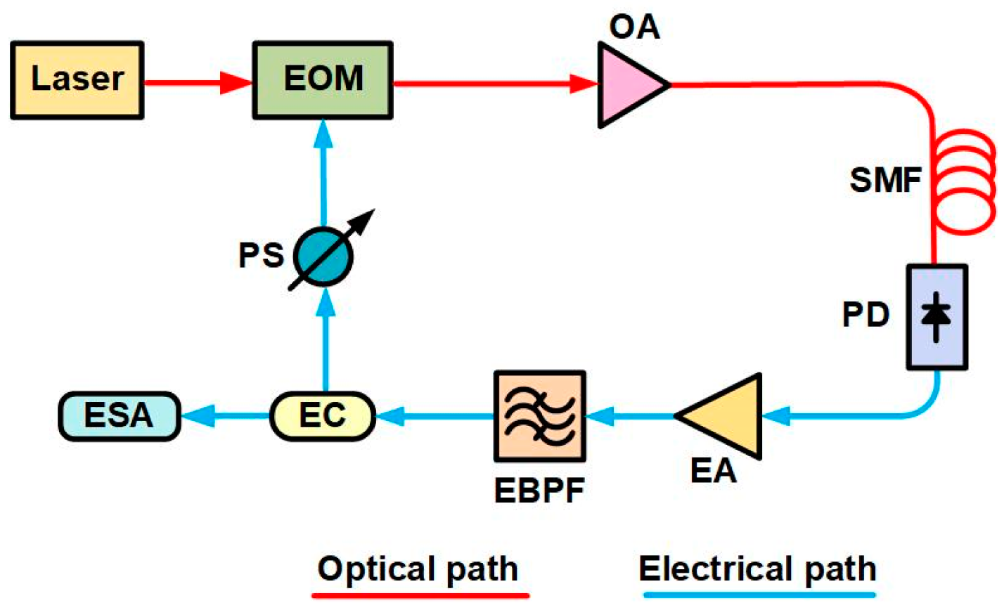
2.1. Single-Loop OEOs
2.2. Performance Parameters
2.2.1. Side-Mode Suppression Ratio
2.2.2. Phase Noise
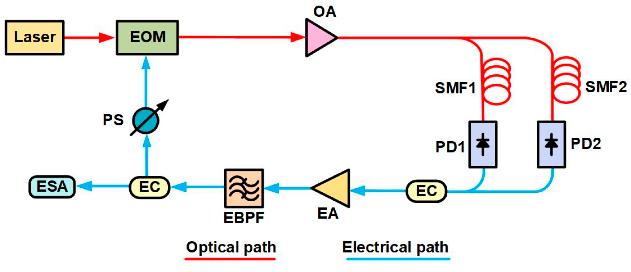
2.3. Dual-Loop OEOs
2.4. Coupled OEOs
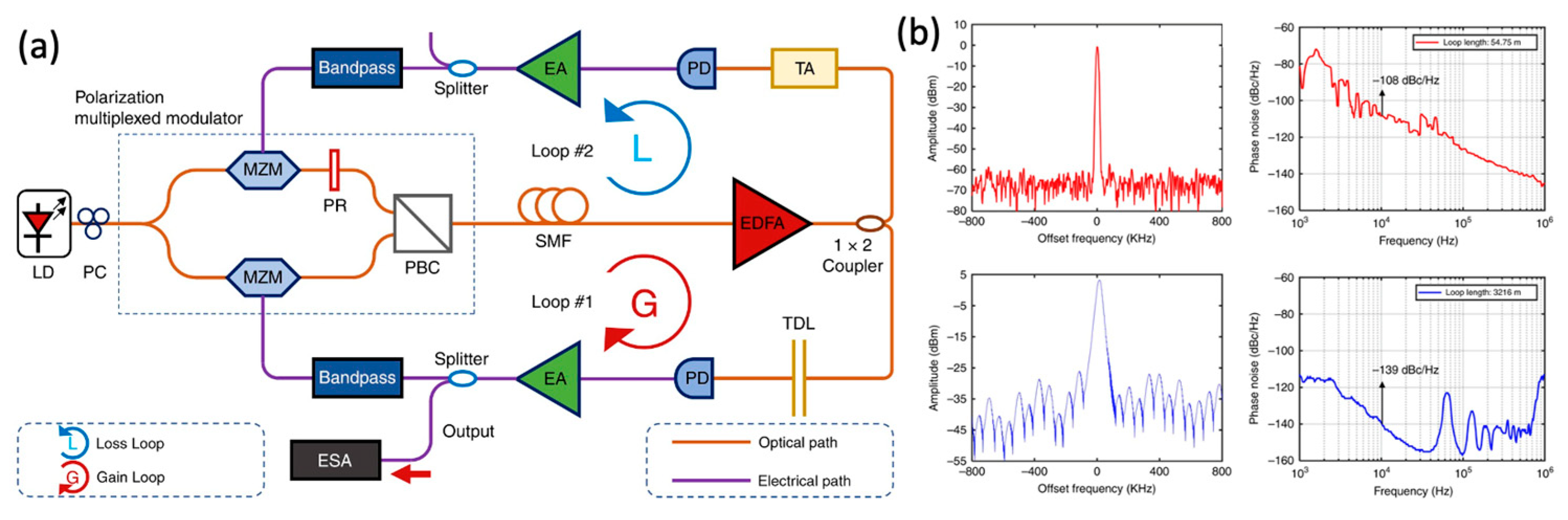
2.5. Parity–Time-Symmetric OEOs
2.6. Summary and Recent Progress
3. Operation Frequency and Stability
3.1. Frequency Stability
3.1.1. Frequency Stability and Influencing Factors
3.1.2. Methods to Improve Frequency Stability
3.2. Frequency-Tunable OEOs
3.3. Broadband OEOs
3.3.1. Multi-Frequency OEOs
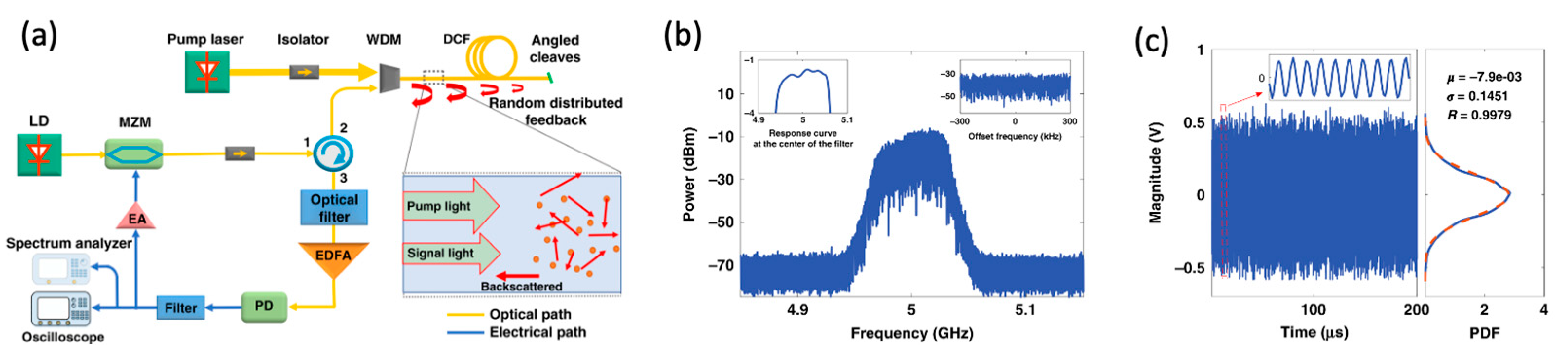
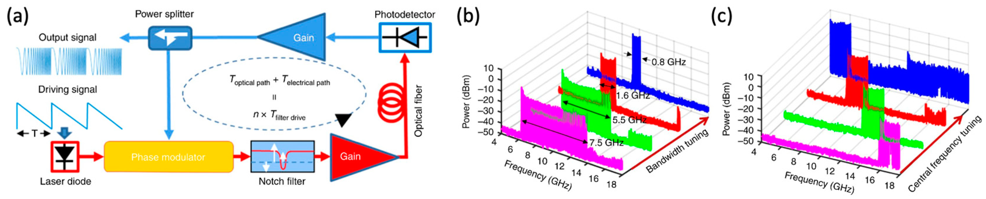
3.3.2. Frequency-Scanning OEOs
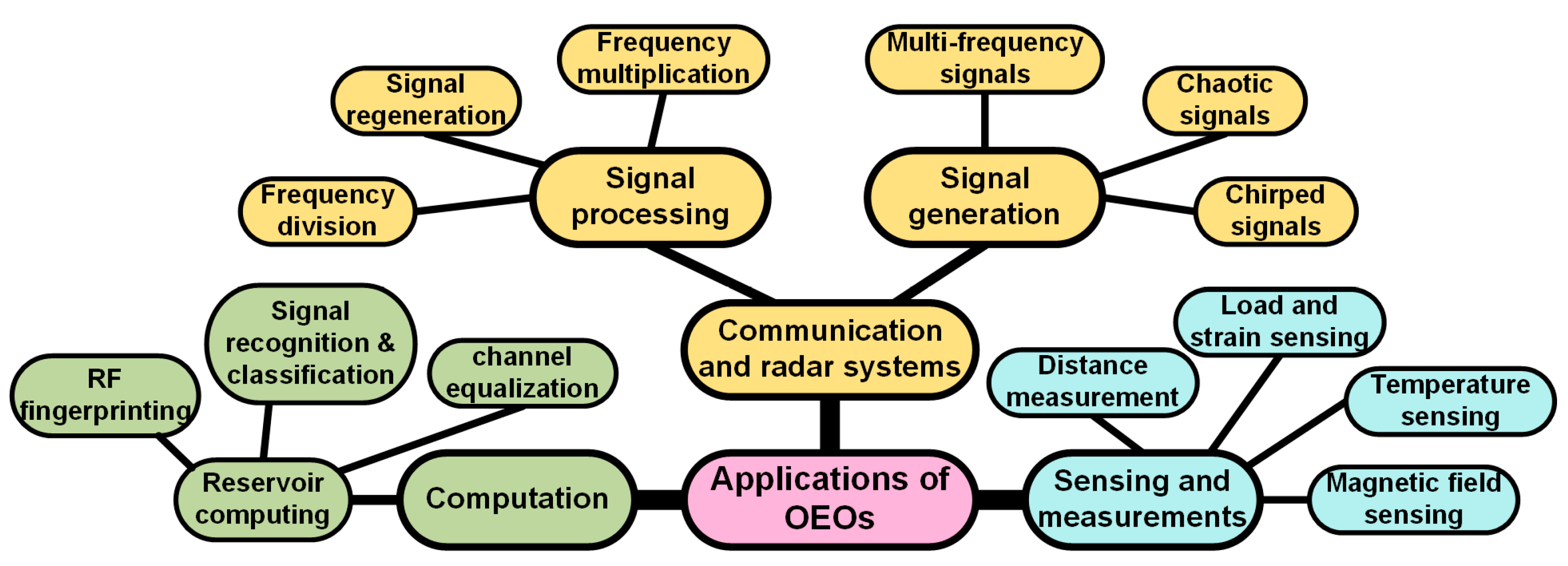
4. Applications

| Application | Architecture | Function | Performance | Ref. | Year |
|---|---|---|---|---|---|
| Sensing and measurements | Dual-loop OEO | Magnetic field sensing | Sensitivity: −16.54 kHz/mT | [75] | 2024 |
| COEO | Temperature-compensated Faraday rotation angle measurement | Sensitivity of the Faraday rotation angle: 375.73 Hz/deg; sensitivity of the temperature: 1.6 kHz/°C | [76] | 2024 | |
| Communication and radar systems | Single-loop OEO with an optical multi-dimensional processing module | A joint radar and communication system | Communication capacity: 335.6 Mbps; range resolution: 0.075 m; maximum unambiguous range: 10.725 m | [7] | 2021 |
| Single-loop OEO | An orthogonal frequency division multiplexing radar and communication joint system. | Communication capacity: 6.4 Gbps; range resolution: 0.075 m; maximum unambiguous range: 300 m | [77] | 2022 | |
| Single-loop broadband OEO | A chaotic radar ranging system | Ranging resolution: 1.4 cm | [80] | 2023 | |
| Signal processing | Single-loop OEO based on injection locking | Improving the quality of arbitrary periodic waveforms | Phase noise improvement: beyond 15 dB; SNR improvement: around 20 dB. | [19] | 2024 |
| Single-loop random OEO based on injection locking | Regenerating continuous wideband signals | SMSR beyond 35.2 dB | [79] | 2024 | |
| Single-loop OEO with a dual-polarization dual-drive MZM | Frequency multiplication | Generating frequency-quadrupled LCWM: bandwidth, 12 GHz; center frequency, 26 GH; phase noise reduced by 20.4 dB | [20] | 2024 | |
| Single-loop OEO | Optical pulse train (OPT) frequency divider | Frequency division factors: 2 and 3; phase noise remained unchanged | [78] | 2024 | |
| Computing | Single-loop narrowband OEO | Reservoir computing for radiofrequency fingerprinting | Accuracy rate: 97% | [81] | 2022 |
| Single-loop narrowband OEO | Reservoir computing for the recognition and classification of IQ-modulated radio signals | Overall accuracy: 61.7% using 600 training examples | [82] | 2024 |
5. Integrated Optoelectronic Oscillators: Advances and Challenges
5.1. Achievements in Integrated OEO Designs
5.1.1. Si-Based OEOs
5.1.2. Integrated PT Symmetric OEOs
5.1.3. Hybrid Integrated OEOs
5.2. Comparison of Current Methods
6. Discussion and Conclusions
Author Contributions
Funding
Data Availability Statement
Conflicts of Interest
References
- Yao, X.S.; Maleki, L. Optoelectronic microwave oscillator. JOSA B 1996, 13, 1725–1735. [Google Scholar] [CrossRef]
- Yao, X.S.; Maleki, L. Optoelectronic oscillator for photonic systems. IEEE J. Quantum Electron. 1996, 32, 1141–1149. [Google Scholar] [CrossRef]
- Spencer, D.T.; Srinivasan, S.; Bluestone, A.; Guerra, D.; Theogarajan, L.; Bowers, J.E. A low phase noise dual loop optoelectronic oscillator as a voltage controlled oscillator with phase locked loop. In Proceedings of the 2014 IEEE Photonics Conference, San Diego, CA, USA, 12–16 October 2014; pp. 412–413. Available online: https://citeseerx.ist.psu.edu/document?repid=rep1&type=pdf&doi=5e3e6084fe6b5d448a2c803c6e57c4f2f8f3466f (accessed on 17 November 2024).
- Qiu, J.; Wei, B.; Yang, L.; Jin, X. Finely Tunable Coupled Optoelectronic Oscillator Based on Injection Locking and Phase Locked Loop. J. Light. Technol. 2023, 41, 5863–5869. [Google Scholar] [CrossRef]
- Cui, T.; Liu, D.; Liu, F.; Zhang, Z.; Tang, Z.; Cui, N.; Pan, S. Tunable optoelectronic oscillator based on a high-Q microring resonator. Opt. Commun. 2023, 536, 129299. [Google Scholar] [CrossRef]
- Huang, L.; Deng, L.; Fu, S.; Tang, M.; Cheng, M.; Zhang, M.; Liu, D. Stable and compact dual-loop optoelectronic oscillator using self-polarization-stabilization technique and multicore fiber. J. Light. Technol. 2018, 36, 5196–5202. [Google Scholar] [CrossRef]
- Xue, Z.; Li, S.; Xue, X.; Zheng, X.; Zhou, B. Photonics-assisted joint radar and communication system based on an optoelectronic oscillator. Opt. Express 2021, 29, 22442–22454. [Google Scholar] [CrossRef] [PubMed]
- Zhang, L.; Poddar, A.; Rohde, U.; Daryoush, A. Analytical and experimental evaluation of SSB phase noise reduction in self-injection locked oscillators using optical delay loops. IEEE Photonics J. 2013, 5, 6602217. [Google Scholar] [CrossRef]
- Bian, Y.; Hirokawa, T.; Lee, W.S.; Chandran, S.; Giewont, K.; Aboketaf, A.; Liu, Q.; Sporer, R.; Rakowski, M.; Dezfulian, K. 300-mm monolithic CMOS silicon photonics foundry technology. CLEO Appl. Technol. 2024, ATu3H-1. [Google Scholar] [CrossRef]
- Hirokawa, T.; Bian, Y.; Giewont, K.; Aboketaf, A.; Chandran, S.; Cho, J.-K.; Chowdhury, Z.; Lee, W.S.; Liu, Q.; Sharma, P. Latest progress and challenges in 300 mm monolithic silicon photonics manufacturing. In Proceedings of the Optical Fiber Communication Conference, San Diego, CA, USA, 24–28 March 2024; Optica Publishing Group: Washington, DC, USA, 2024; p. Th3H-2. Available online: https://opg.optica.org/abstract.cfm?uri=ofc-2024-Th3H.2 (accessed on 24 November 2024).
- Liu, Q.; Aboketaf, A.; Pal, S.; Mosleh, S.; Banihashemian, S.F.; Pavadai, S.; Lee, J.-C.; Bian, Y.; Gong, M.; Orner, B. High-Power Micro-Ring Modulator and Multi-Channel Coupled Ring Resonator for WDM Design on a 300-mm Monolithic Foundry Platform. In Proceedings of the 2024 Optical Fiber Communications Conference and Exhibition (OFC), San Diego, CA, USA, 24–28 March 2024; pp. 1–3. Available online: https://ieeexplore.ieee.org/abstract/document/10526519/ (accessed on 24 November 2024).
- Zou, F.; Zou, L.; Yang, B.; Ma, Q.; Zou, X.; Zou, J.; Chen, S.; Milosevic, D.; Cao, Z.; Liu, H. Optoelectronic oscillator for 5G wireless networks and beyond. J. Phys. Appl. Phys. 2021, 54, 423002. [Google Scholar] [CrossRef]
- Liu, Q.; Ge, J.; Fok, M.P. Microwave photonic multiband filter with independently tunable passband spectral properties. Opt. Lett. 2018, 43, 5685–5688. [Google Scholar] [CrossRef]
- Wu, T.; Jiang, Y.; Ma, C.; Jia, Z.; Bai, G.; Zi, Y.; Huang, F. Simultaneous Triangular Waveform Signal and Microwave Signal Generation Based on Dual-Loop Optoelectronic Oscillator. IEEE Photonics J. 2016, 8, 1–10. [Google Scholar] [CrossRef]
- Yan, J.; Liang, A.; Xin, F.; Liu, Q. An Optical Microwave Generator based on Stimulated Brillouin Scattering with Fine Tunability. In Proceedings of the Conference on Lasers and Electro-Optics, San Jose, CA, USA, 13–18 May 2018; Optica Publishing Group: Washington, DC, USA, 2018; p. JW2A.181. [Google Scholar] [CrossRef]
- Li, M.; Hao, T.; Li, W.; Dai, Y. Tutorial on optoelectronic oscillators. APL Photonics 2021, 6, 061101. [Google Scholar] [CrossRef]
- Hao, T.; Liu, Y.; Tang, J.; Cen, Q.; Li, W.; Zhu, N.; Dai, Y.; Capmany, J.; Yao, J.; Li, M. Recent advances in optoelectronic oscillators. Adv. Photonics 2020, 2, 044001. [Google Scholar] [CrossRef]
- Tang, J.; Hao, T.; Li, W.; Domenech, D.; Baños, R.; Muñoz, P.; Zhu, N.; Capmany, J.; Li, M. Integrated optoelectronic oscillator. Opt. Express 2018, 26, 12257–12265. [Google Scholar] [CrossRef] [PubMed]
- Liu, M.; Liu, S.; Yang, L.; Du, C.; Liu, H.; Pan, S. Improving the Quality of Arbitrary Periodic Waveform via Injection-Locking of an Optoelectronic Oscillator. IEEE Trans. Microw. Theory Tech. 2024, 72, 6678–6685. [Google Scholar] [CrossRef]
- Zhang, W.; Liu, Y.; Wang, B. Low-Phase-Noise Ultra-Wide Arbitrary Waveforms Generation Using a Wideband Injection-Locked Optoelectronic Oscillator. J. Light. Technol. 2024, 42, 7693–7702. [Google Scholar] [CrossRef]
- Zhou, P.; Pan, S.; Zhu, D.; Guo, R.; Zhang, F.; Zhao, Y. A Compact Optoelectronic Oscillator Based on an Electroabsorption Modulated Laser. IEEE Photonics Technol. Lett. 2014, 26, 86–88. [Google Scholar] [CrossRef]
- Zhao, S.; Yan, J. Low phase noise optoelectronic oscillator based on an electroabsorption modulated laser. Appl. Opt. 2019, 58, 4512–4517. [Google Scholar] [CrossRef]
- Eliyahu, D.; Maleki, L. Low phase noise and spurious level in multi-loop opto-electronic oscillators. In Proceedings of the IEEE International Frequency Control Symposium and PDA Exhibition Jointly with the 17th European Frequency and Time Forum, Tampa, FL, USA, 4–8 May 2003; pp. 405–410. [Google Scholar]
- Leeson, D.B. A simple model of feedback oscillator noise spectrum. Proc. IEEE 1966, 54, 329–330. [Google Scholar] [CrossRef]
- Hasanuzzaman, G.K.M.; Kanno, A.; Dat, P.T.; Iezekiel, S. Self-Oscillating Optical Frequency Comb: Application to Low Phase Noise Millimeter Wave Generation and Radio-Over-Fiber Link. J. Light. Technol. 2018, 36, 4535–4542. [Google Scholar] [CrossRef]
- Yang, J.; Jin-Long, Y.; Yao-Tian, W.; Li-Tai, Z.; En-Ze, Y. An Optical Domain Combined Dual-Loop Optoelectronic Oscillator. IEEE Photonics Technol. Lett. 2007, 19, 807–809. [Google Scholar] [CrossRef]
- Hasanuzzaman, G.K.M.; Iezekiel, S.; Kanno, A. 94.5 GHz Dual-loop Optoelectronic Oscillator. In Proceedings of the 2023 International Conference on Electrical, Computer and Communication Engineering (ECCE), Chittagong, Bangladesh, 23–25 February 2023; pp. 1–4. [Google Scholar]
- Jia, S.; Yu, J.; Wang, J.; Wang, W.; Wu, Q.; Huang, G.; Yang, E. A Novel Optoelectronic Oscillator Based on Wavelength Multiplexing. IEEE Photonics Technol. Lett. 2015, 27, 213–216. [Google Scholar] [CrossRef]
- Li, X.; Zhu, D.; Ding, J.; Hu, X.; Pan, S. Simulation investigation of coupled optoelectronic oscillator with high supermode suppression ratio. In Proceedings of the Seventh Asia Pacific Conference on Optics Manufacture and 2021 International Forum of Young Scientists on Advanced Optical Manufacturing (APCOM and YSAOM 2021), Shanghai, China, 28–31 October 2022; Volume 12166, pp. 1829–1834. [Google Scholar]
- Zeng, H.; Yan, J. GHz repetition rate tunable optical pulses generation using a SBS-based coupled optoelectronic oscillator. Opt. Commun. 2024, 555, 130234. [Google Scholar] [CrossRef]
- Liu, Y.; Hao, T.; Li, W.; Capmany, J.; Zhu, N.; Li, M. Observation of parity-time symmetry in microwave photonics. Light Sci. Appl. 2018, 7, 38. [Google Scholar] [CrossRef] [PubMed]
- Zhang, J.; Yao, J. Parity-time–symmetric optoelectronic oscillator. Sci. Adv. 2018, 4, eaar6782. [Google Scholar] [CrossRef] [PubMed]
- Zhang, F.; Lin, X.; Wu, Z.; Xia, G. A Symmetric Parity–Time Coupled Optoelectronic Oscillator Using a Polarization–Dependent Spatial Structure. Photonics 2023, 10, 1236. [Google Scholar] [CrossRef]
- Fu, J.; Dai, Z.; Han, X.; Yao, J. Wavelength-Space Parity-Time Symmetric Optoelectronic Oscillator Using a Chirped Fiber Bragg Grating. IEEE Photonics Technol. Lett. 2024, 36, 187–190. [Google Scholar] [CrossRef]
- Lelièvre, O.; Crozatier, V.; Berger, P.; Baili, G.; Llopis, O.; Dolfi, D.; Nouchi, P.; Goldfarb, F.; Bretenaker, F.; Morvan, L. A model for designing ultralow noise single-and dual-loop 10-GHz optoelectronic oscillators. J. Light. Technol. 2017, 35, 4366–4374. [Google Scholar] [CrossRef]
- Chen, J.; Zheng, Y.; Xue, C.; Zhang, C.; Chen, Y. Filtering effect of SiO2 optical waveguide ring resonator applied to optoelectronic oscillator. Opt. Express 2018, 26, 12638–12647. [Google Scholar] [CrossRef]
- Yu, Y.; Tang, H.; Liu, W.; Hu, X.; Zhang, Y.; Xiao, X.; Yu, Y.; Zhang, X. Frequency stabilization of the tunable optoelectronic oscillator based on anultra-high-Q microring resonator. IEEE J. Sel. Top. Quantum Electron. 2019, 26, 1–9. [Google Scholar] [CrossRef]
- Zhang, J.; Wang, Y.; Ding, Q. Single-loop tunable PT-symmetric optoelectronic oscillator based on a phase modulator. Appl. Opt. 2024, 63, 566–574. [Google Scholar] [CrossRef] [PubMed]
- Kaba, M.; Li, H.-W.; Daryoush, A.S.; Vilcot, J.-P.; Decoster, D.; Chazelas, J.; Bouwmans, G.; Quiquempois, Y.; Deborgies, F. Improving thermal stability of opto-electronic oscillators. IEEE Microw. Mag. 2006, 7, 38–47. [Google Scholar] [CrossRef]
- Zhang, L.; Poddar, A.K.; Rohde, U.L.; Daryoush, A.S. Comparison of optical self-phase locked loop techniques for frequency stabilization of oscillators. IEEE Photonics J. 2014, 6, 1–15. [Google Scholar] [CrossRef]
- Wang, Y.; Yan, J. Stability improvement of a dual-loop optoelectronic oscillator based on self-phase locking. Appl. Opt. 2022, 61, 8912–8916. [Google Scholar] [CrossRef]
- Jiang, Y.; Bai, G.; Hu, L.; Li, H.; Zhou, Z.; Xu, J.; Wang, S. Frequency locked single-mode optoelectronic oscillator by using low frequency RF signal injection. IEEE Photonics Technol. Lett. 2013, 25, 382–384. [Google Scholar] [CrossRef]
- Zhou, W.; Blasche, G. Injection-locked dual opto-electronic oscillator with ultra-low phase noise and ultra-low spurious level. IEEE Trans. Microw. Theory Tech. 2005, 53, 929–933. [Google Scholar] [CrossRef]
- Williams, C.; Quinlan, F.; Davila-Rodriguez, J.; Delfyett, P.J. Optical injection locking of a coupled optoelectronic oscillator. In Proceedings of the Conference on Lasers and Electro-Optics, Baltimore, MD, USA, 2–4 June 2009; Optica Publishing Group: Washington, DC, USA, 2009; p. CThF3. Available online: https://opg.optica.org/abstract.cfm?uri=CLEO-2009-CThF3 (accessed on 17 November 2024).
- Guan, S.; Cen, Q.; Yin, F.; Xu, K.; Dai, Y. Self-injection-locked optoelectronic oscillator based on frequency conversion filtering. J. Light. Technol. 2021, 40, 1888–1894. [Google Scholar] [CrossRef]
- Zhenghua, Z.; Chun, Y.; Zhewei, C.; Yuhua, C.; Xianghua, L. An ultra-low phase noise and highly stable optoelectronic oscillator utilizing IL-PLL. IEEE Photonics Technol. Lett. 2015, 28, 516–519. [Google Scholar] [CrossRef]
- Fu, R.; Jin, X.; Zhu, Y.; Jin, X.; Yu, X.; Zheng, S.; Chi, H.; Zhang, X. Frequency stability optimization of an OEO using phase-locked-loop and self-injection-locking. Opt. Commun. 2017, 386, 27–30. [Google Scholar] [CrossRef]
- Liu, Y.; Choudhary, A.; Marpaung, D.; Eggleton, B.J. Integrated microwave photonic filters. Adv. Opt. Photonics 2020, 12, 485–555. [Google Scholar] [CrossRef]
- Liu, Q.; Fok, M.P. Adaptive photonic RF spectral shaper. Opt. Express 2020, 28, 24789–24798. [Google Scholar] [CrossRef]
- Eliyahu, D.; Maleki, L. Tunable, ultra-low phase noise YIG based opto-electronic oscillator. In Proceedings of the IEEE MTT-S International Microwave Symposium Digest, Philadelphia, PA, USA, 8–13 June 2003; Volume 3, pp. 2185–2187. [Google Scholar]
- Qi, H.; Lu, D.; Zhao, L. A Frequency-Tunable Coupled Optoelectronic Oscillator. In Proceedings of the 2021 Asia Communications and Photonics Conference (ACP), Shanghai, China, 24–27 October 2021; pp. 1–3. Available online: https://ieeexplore.ieee.org/abstract/document/9738407 (accessed on 17 November 2024).
- Peng, H.; Xie, X.; Zhang, C.; Sun, T.; Guo, P.; Chen, F.; Zhu, L.; Hu, W.; Chen, Z. Widely Tunable Dual Loop Optoelectronic Oscillator based on a Single-Bandpass Microwave Photonic Filter and a Recirculating Delay Line. In Proceedings of the 2014 Asia Communications and Photonics Conference (ACP), Shanghai, China, 11–14 November 2014; pp. 1–3. Available online: https://ieeexplore.ieee.org/abstract/document/8687583 (accessed on 17 November 2024).
- Wang, A.; Wo, J.; Zhang, J.; Luo, X.; Xu, X.; Zhang, D.; Du, P.; Yu, L. Radio-frequency arbitrary waveform generation based on dispersion compensated tunable optoelectronic oscillator with ultra-wide tunability. Chin. Opt. Lett. 2017, 15, 100603. [Google Scholar] [CrossRef]
- Li, C.; Wang, Y.; Wang, W.; Xu, Z.; Zhao, B.; Wang, H.; Tang, D. Widely Tunable Optoelectronic Oscillator Using a Dispersion-Induced Single Bandpass MPF. IEEE Photonics Technol. Lett. 2018, 30, 7–10. [Google Scholar] [CrossRef]
- Li, W.; Yao, J. A Wideband Frequency Tunable Optoelectronic Oscillator Incorporating a Tunable Microwave Photonic Filter Based on Phase-Modulation to Intensity-Modulation Conversion Using a Phase-Shifted Fiber Bragg Grating. IEEE Trans. Microw. Theory Tech. 2012, 60, 1735–1742. [Google Scholar] [CrossRef]
- Yang, B.; Jin, X.; Zhang, X.; Zheng, S.; Chi, H.; Wang, Y. A wideband frequency-tunable optoelectronic oscillator based on a narrowband phase-shifted FBG and wavelength tuning of laser. IEEE Photonics Technol. Lett. 2011, 24, 73–75. [Google Scholar] [CrossRef]
- Dai, Z.; Fan, Z.; Li, P.; Yao, J. Frequency-tunable parity-time-symmetric optoelectronic oscillator using a polarization-dependent Sagnac loop. J. Light. Technol. 2020, 38, 5327–5332. [Google Scholar] [CrossRef]
- Shi, M.; Yi, L.; Hu, W. SBS-based OEO with high tuning resolution and wide tuning range by selecting different-order phase modulation sideband as pump. In Proceedings of the Optical Fiber Communication Conference, San Diego, CA, USA, 11–15 March 2018; Optica Publishing Group: Washington, DC, USA, 2018; p. M1H-4. Available online: https://opg.optica.org/abstract.cfm?uri=OFC-2018-M1H.4 (accessed on 17 November 2024).
- Peng, H.; Zhang, C.; Xie, X.; Sun, T.; Guo, P.; Zhu, X.; Zhu, L.; Hu, W.; Chen, Z. Tunable DC-60 GHz RF generation utilizing a dual-loop optoelectronic oscillator based on stimulated Brillouin scattering. J. Light. Technol. 2015, 33, 2707–2715. [Google Scholar] [CrossRef]
- Wu, Z.; Zhang, J.; Wang, Y. A Frequency Stable and Tunable Optoelectronic Oscillator Using an Optical Phase Shifter and a Phase-shifted Fiber Bragg Grating. Curr. Opt. Photonics 2022, 6, 634–641. [Google Scholar]
- Ding, Q.; Wang, M.; Zhang, J.; Mu, H.; Wang, C.; Fan, G. A precisely frequency-tunable parity-time-symmetric optoelectronic oscillator. J. Light. Technol. 2020, 38, 6569–6577. [Google Scholar] [CrossRef]
- Zhou, P.; Zhang, F.; Pan, S. A multi-frequency optoelectronic oscillator based on a single phase-modulator. In Proceedings of the CLEO: Applications and Technology, San Jose, CA, USA, 8–13 June 2015; Optica Publishing Group: Washington, DC, USA, 2015; p. JTh2A-39. Available online: https://opg.optica.org/abstract.cfm?uri=cleo_at-2015-JTh2A.39 (accessed on 17 November 2024).
- Yin, B.; Wang, M.; Wu, S.; Tang, Y.; Feng, S.; Zhang, H. High sensitivity axial strain and temperature sensor based on dual-frequency optoelectronic oscillator using PMFBG Fabry-Perot filter. Opt. Express 2017, 25, 14106–14113. [Google Scholar] [CrossRef]
- Wu, B.; Wang, M.; Dong, Y.; Tang, Y.; Mu, H.; Li, H.; Yin, B.; Yan, F.; Han, Z. Magnetic field sensor based on a dual-frequency optoelectronic oscillator using cascaded magnetostrictive alloy-fiber Bragg grating-Fabry Perot and fiber Bragg grating-Fabry Perot filters. Opt. Express 2018, 26, 27628–27638. [Google Scholar] [CrossRef] [PubMed]
- Zhou, P.; Zhang, F.; Pan, S. A tunable multi-frequency optoelectronic oscillator based on stimulated Brillouin scattering. In Proceedings of the 2015 14th International Conference on Optical Communications and Networks (ICOCN), Nanjing, China, 3–5 July 2015; pp. 1–3. Available online: https://ieeexplore.ieee.org/abstract/document/7203635/ (accessed on 17 November 2024).
- Zhang, J.; Wang, Y.; Li, X.; Liu, Z.; Wo, J. Tunable multi-frequency optoelectronic oscillator based on a microwave photonic filter and an electrical filter. Opt. Quantum Electron. 2021, 53, 407. [Google Scholar] [CrossRef]
- Fu, Z.; Zeng, Z.; Tian, H.; Lyu, W.; Zhang, Z.; Zhang, S.; Zhang, Y.; Li, H.; Liu, Y. Wide-Range Tunable Coherent Dual-frequency Microwave Signal Generation with Low Spurious Components in Optoelectronic Oscillator. J. Light. Technol. 2024, 42, 7443–7450. Available online: https://ieeexplore.ieee.org/abstract/document/10551635/ (accessed on 16 January 2025). [CrossRef]
- Ge, Z.; Hao, T.; Capmany, J.; Li, W.; Zhu, N.; Li, M. Broadband random optoelectronic oscillator. Nat. Commun. 2020, 11, 5724. [Google Scholar] [CrossRef]
- Hao, T.; Tang, J.; Li, W.; Zhu, N.; Li, M. Harmonically Fourier domain mode-locked optoelectronic oscillator. IEEE Photonics Technol. Lett. 2019, 31, 427–430. [Google Scholar] [CrossRef]
- Hao, T.; Tang, J.; Shi, N.; Li, W.; Zhu, N.; Li, M. Dual-chirp Fourier domain mode-locked optoelectronic oscillator. Opt. Lett. 2019, 44, 1912–1915. [Google Scholar] [CrossRef]
- Hao, P.; Dong, Z.; Han, D.; Huang, C.; Yao, X.S. Simultaneous dual-band frequency-agile microwave signal generation with a dual loop Fourier domain mode locked optoelectronic oscillator. J. Light. Technol. 2024, 42, 7710–7716. Available online: https://ieeexplore.ieee.org/abstract/document/10475433/ (accessed on 16 January 2025). [CrossRef]
- Zhu, S.; Fan, X.J.; Xu, B.R.; Sun, W.H.; Li, M.; Zhu, N.H.; Li, W. Polarization manipulated Fourier domain mode-locked optoelectronic oscillator. J. Light. Technol. 2020, 38, 5270–5277. [Google Scholar] [CrossRef]
- Hao, T.; Tang, J.; Li, W.; Zhu, N.; Li, M. Tunable Fourier domain mode-locked optoelectronic oscillator using stimulated Brillouin scattering. IEEE Photonics Technol. Lett. 2018, 30, 1842–1845. [Google Scholar] [CrossRef]
- Hao, T.; Cen, Q.; Dai, Y.; Tang, J.; Li, W.; Yao, J.; Zhu, N.; Li, M. Breaking the limitation of mode building time in an optoelectronic oscillator. Nat. Commun. 2018, 9, 1839. [Google Scholar] [CrossRef]
- Zhao, X.; Wu, B.; Wang, M.; Xiao, S.; Li, J.; Cai, Y.; Yan, F. Enhanced sensitivity of magnetic field sensing using L-shaped dual Terfenol-D-FBGs based on the Vernier effect and a dual-loop optoelectronic oscillator. Opt. Express 2024, 32, 29988–30002. [Google Scholar] [CrossRef]
- Feng, D.; Liu, Y.; Wang, H.; Deng, M. Faraday Rotation Angle Measurement Based on Coupled Optoelectronic Oscillator with Temperature Compensation. J. Light. Technol. 2024, 42, 8137–8143. Available online: https://ieeexplore.ieee.org/abstract/document/10608388/ (accessed on 16 January 2025). [CrossRef]
- Xue, Z.; Li, S.; Li, J.; Xue, X.; Zheng, X.; Zhou, B. OFDM radar and communication joint system using opto-electronic oscillator with phase noise degradation analysis and mitigation. J. Light. Technol. 2022, 40, 4101–4109. [Google Scholar] [CrossRef]
- Li, P.; Shao, K.; Zhang, Y.; Pan, S. Optical pulse repetition rate division using an optoelectronic oscillator. Chin. Opt. Lett. 2024, 22, 043902. [Google Scholar] [CrossRef]
- Ma, Y.; Linghu, S.; Chen, B.; Gu, F. Continuous ultra-wideband signal regeneration in random optoelectronic oscillators through injection locking. Opt. Express 2024, 32, 9847–9856. [Google Scholar] [CrossRef]
- Xu, Z.; Tian, H.; Zhang, L.; Zhao, Q.; Zhang, Z.; Zhang, S.; Li, H.; Liu, Y. High-resolution radar ranging based on the ultra-wideband chaotic optoelectronic oscillator. Opt. Express 2023, 31, 22594–22602. [Google Scholar] [CrossRef]
- Dai, H.; Chembo, Y.K. RF fingerprinting based on reservoir computing using narrowband optoelectronic oscillators. J. Light. Technol. 2022, 40, 7060–7071. [Google Scholar] [CrossRef]
- Klimko, B.H.; Dai, H.; Chembo, Y.K. Resource-constrained narrowband optoelectronic oscillator-based reservoir computing for classification of modulated signals. Opt. Lett. 2024, 49, 3608–3611. [Google Scholar] [CrossRef] [PubMed]
- Ilgaz, M.A.; Batagelj, B. Opto-electronic oscillators for micro-and millimeter wave signal generation. Electronics 2021, 10, 857. [Google Scholar] [CrossRef]
- Zhang, W.; Yao, J. A silicon photonic integrated frequency-tunable optoelectronic oscillator. In Proceedings of the 2017 International Topical Meeting on Microwave Photonics (MWP), Beijing, China, 23–26 October 2017; pp. 1–4. Available online: https://ieeexplore.ieee.org/abstract/document/8168643/ (accessed on 17 November 2024).
- Pan, B.; Lu, D.; Zhang, L.; Zhao, L. A widely tunable optoelectronic oscillator based on directly modulated dual-mode laser. IEEE Photonics J. 2015, 7, 1–7. [Google Scholar] [CrossRef]
- Liu, P.; Xie, Z.; Lin, D.; Lu, M.; Cheng, W.; Hu, G.; Yun, B.; Cui, Y. Parity-time symmetric tunable OEO based on dual-wavelength and cascaded PS-FBGs in a single-loop. Opt. Express 2021, 29, 35377–35386. [Google Scholar] [CrossRef] [PubMed]
- Ahmadfard, F.; Hosseini, S.E. Design and simulation of a tunable parity-time symmetric optoelectronic oscillator utilizing integrated components. Sci. Rep. 2024, 14, 16014. [Google Scholar] [CrossRef] [PubMed]
- Tian, Y.; Han, Z.; Wang, L.; Zheng, Y.; Zhang, P.; Jiang, Y.; Xiao, H.; Zhou, X.; Yuan, M.; Low, M.X. Integrated Ultra-Wideband Tunable Fourier Domain Mode-Locked Optoelectronic Oscillator. 2024. Available online: https://www.researchsquare.com/article/rs-4743222/latest (accessed on 17 November 2024).
- Dziallas, G.; Fatemi, A.; Peczek, A.; Tarar, M.; Kissinger, D.; Zimmermann, L.; Malignaggi, A.; Kahmen, G. A −115 dBc/Hz Integrated Optoelectronic Oscillator in a BiCMOS Silicon Photonic Technology. In Proceedings of the 2021 IEEE MTT-S International Microwave Symposium (IMS), Atlanta, GA, USA, 7–25 June 2021; pp. 23–26. Available online: https://ieeexplore.ieee.org/abstract/document/9574906/ (accessed on 17 November 2024).
- Li, J.; Pu, T.; Zheng, J.; Zhang, Y.; Shi, Y.; Shao, W.; Zhang, X.; Meng, X.; Liu, J.; Liu, J. All-optical gain optoelectronic oscillator based on a dual-frequency integrated semiconductor laser: Potential to break the bandwidth limitation in the traditional OEO configuration. Opt. Express 2021, 29, 1064–1075. [Google Scholar] [CrossRef] [PubMed]
- Do, P.T.; Alonso-Ramos, C.; Le Roux, X.; Ledoux, I.; Journet, B.; Cassan, E. Wideband tunable microwave signal generation in a silicon-micro-ring-based optoelectronic oscillator. Sci. Rep. 2020, 10, 6982. [Google Scholar] [CrossRef]
- Hong, X.; Cheng, Y.; Wang, B.; Zhang, W. On-Chip photonic generation of tunable wideband phase-coded linearly-chirped microwave waveforms. J. Light. Technol. 2023, 41, 6199–6207. [Google Scholar] [CrossRef]
- Hong, X.; Yu, Z.; Yu, W.; Wang, B.; Zhang, W. Independently Tunable Dual-Band Linearly-Chirped Microwave Waveforms Generation on a Silicon Photonic Chip. J. Light. Technol. 2024, 42, 5476–5484. Available online: https://ieeexplore.ieee.org/abstract/document/10517378/ (accessed on 12 January 2025). [CrossRef]
- Ivanov, V.; Voronkov, G.; Golubchikov, A.; Kuznetsov, I.; Grakhova, E.; Kutluyarov, R. PIC-based opto-electronic oscillator for communication and sensing applications. J. Opt. Technol. 2023, 90, 719–724. [Google Scholar] [CrossRef]
- Wang, L.; Xiao, X.; Xu, L.; Liu, Y.; Chen, Y.; Yu, Y.; Zhang, X. On-chip tunable parity-time symmetric optoelectronic oscillator. Adv. Photonics Nexus 2023, 2, 016004. [Google Scholar] [CrossRef]
- Zhang, G.; Hao, T.; Cen, Q.; Li, M.; Shi, N.; Li, W.; Xiao, X.; Qi, N.; Dong, J.; Dai, Y. Hybrid-integrated wideband tunable optoelectronic oscillator. Opt. Express 2023, 31, 16929–16938. [Google Scholar] [CrossRef]
- Chen, G.; Lu, D.; Guo, L.; Deng, Q.; Zhao, W.; Zhao, L. An Optoelectronic Oscillator based on Self-Injection-Locked Monolithic Integrated Dual-mode Amplified Feedback Laser. In Proceedings of the Asia Communications and Photonics Conference, Guangzhou, China, 10–13 November 2017; Optica Publishing Group: Washington, DC, USA, 2017; p. Su2A.10. [Google Scholar]
- Li, P.; Dai, Z.; Fan, Z.; Yan, L.; Yao, J. Parity–time-symmetric frequency-tunable optoelectronic oscillator with a single dual-polarization optical loop. Opt. Lett. 2020, 45, 3139–3142. [Google Scholar] [CrossRef] [PubMed]
- Ma, R.; Huang, Z.; Gao, S.; Wang, J.; Wang, X.; Zhang, X.; Hao, P.; Yao, X.S.; Cai, X. Ka-band thin film lithium niobate photonic integrated optoelectronic oscillator. Photonics Res. 2024, 12, 1283–1293. [Google Scholar] [CrossRef]
- Han, J.-Y.; Huang, Y.-T.; Hao, Y.-Z.; Tang, M.; Wang, F.-L.; Xiao, J.-L.; Yang, Y.-D.; Huang, Y.-Z. Wideband frequency-tunable optoelectronic oscillator with a directly modulated AlGaInAs/InP integrated twin-square microlaser. Opt. Express 2018, 26, 31784–31793. [Google Scholar] [CrossRef] [PubMed]
- Zhang, X.; Zheng, J.; Pu, T.; Zhang, Y.; Shi, Y.; Li, J.; Li, Y.; Zhu, H.; Chen, X. Simple frequency-tunable optoelectronic oscillator using integrated multi-section distributed feedback semiconductor laser. Opt. Express 2019, 27, 7036–7046. [Google Scholar] [CrossRef] [PubMed]
- Teng, C.; Zou, X.; Li, P.; Pan, W.; Yan, L. Wideband Frequency-Tunable Parity-Time Symmetric Optoelectronic Oscillator Based on Hybrid Phase and Intensity Modulations. J. Light. Technol. 2020, 38, 5406–5411. [Google Scholar] [CrossRef]
- Fan, Z.; Zhang, W.; Qiu, Q.; Yao, J. Hybrid Frequency-Tunable Parity-Time Symmetric Optoelectronic Oscillator. J. Light. Technol. 2020, 38, 2127–2133. [Google Scholar] [CrossRef]
- Liu, P.; Zheng, P.; Yang, H.; Lin, D.; Hu, G.; Yun, B.; Cui, Y. Parity-time symmetric frequency-tunable optoelectronic oscillator based on a Si3N4 microdisk resonator. Appl. Opt. 2021, 60, 1930–1936. [Google Scholar] [CrossRef] [PubMed]
- Zou, F.; Zou, L.; Lai, Y.; Xie, C.; Luo, J.; Milosevic, D.; Yan, L.; Pan, W.; Liu, Y.; Cao, Z.; et al. Parity-Time Symmetric Optoelectronic Oscillator Based on an Integrated Mode-Locked Laser. IEEE J. Quantum Electron. 2021, 57, 1–9. [Google Scholar] [CrossRef]
- Wang, L.; Liu, Y.; Chen, Y.; Gou, W.; Cui, S.; Yu, Y.; Xiao, X.; Yu, Y.; Zhang, X. Generation of Reconfigurable Linearly Chirped Microwave Waveforms Based On Fourier domain Mode-Locked Optoelectronic Oscillator. J. Light. Technol. 2022, 40, 85–92. [Google Scholar] [CrossRef]
- Gou, W.; Wang, L.; Liu, Y.; Chen, Y.; Yu, Y.; Yu, Y.; Zhang, X. Generation of Phase-Coded LFM Signals Based on Fourier Domain Mode-Locked Optoelectronic Oscillator. J. Light. Technol. 2023, 41, 6142–6148. [Google Scholar] [CrossRef]


| Method | Key Architecture | Frequency (GHz) | Fiber Length | Phase Noise @ 10 kHz (dBc/Hz) | SMSR (dB) | Ref. | Year |
|---|---|---|---|---|---|---|---|
| Dual-loop | WDM | 20 | 2 km; 3 km | −120.6 | 70 | [28] | 2015 |
| Balanced PD | 11.84 | 2 m; 2 km | −110 | 60 | [25] | 2018 | |
| Polymer-based modulator | 94.5 | 1 km; 2.5 km | −70 | 40 | [27] | 2023 | |
| High-Q optical resonators | Optical ring resonator | 2.137 | 5 m | −100.54 | 59 | [36] | 2018 |
| MRR w/frequency stabilization | 12.23 | NA | −95 | 55 | [37] | 2020 | |
| MRR | 25.65 | NA | −88 | 49.47 | [5] | 2023 | |
| PT symmetry | DPMZM | 6.19 | 54.75 m; 3.216 km | −139 | 55 | [31] | 2018 |
| Polarization control | 9.867 | 9.166 km | −142.5 | NA | [32] | 2018 | |
| COEO | 10 | 100 m | −109.1 | 51.4 | [33] | 2023 | |
| WDM | 4.07 | 10 km | −118 | 32 | [34] | 2024 | |
| Dual-mode optical PM | 18 | 7 km | −133.8 | 53 | [38] | 2024 |
| Method | Key Architecture | Frequency Range (GHz) | Phase Noise @ 10 kHz (dBc/Hz) | Ref. | Year |
|---|---|---|---|---|---|
| YIG-tuned | multi-loop OEO | 6–12 | −128 @ all frequency | [50] | 2003 |
| COEO | 8–21 | −126 @ 15 GHz; | [51] | 2021 | |
| MPF-tuned | PS FBG and two cascaded PM-based MPFs; single-loop OEO | 3–28 | −102 @ 10 GHz | [55] | 2012 |
| PS FBG and an MZM-based MPF; single-loop OEO | 8.4–11.8 | −100 @ 10.6 GHz | [56] | 2012 | |
| BOS, PM, and DCF-based MPF; dual-loop OEO | 10.23–26.69 | −100 @ 15 GHz, 20 GHz, 25 GHz | [52] | 2014 | |
| FBG FP and PM-based MPF; dual-loop OEO | 3.5–45 | −112.93 @ 44.3 GHz; | [53] | 2017 | |
| TBPOF and PM-based MPF; dual-loop OEO | 3.5–17.1 | −100 @ 7.8 GHz | [6] | 2018 | |
| BOS, MZM, and LCFBG-based MPF; dual-loop OEO | 4.087–13.05 | −96.9 @6.5 GHz | [54] | 2018 | |
| SBS-based MPF; dual-loop OEO | 5.34–38.34 | −120 @ 100 kHz @ all frequency | [58] | 2018 | |
| PS FBG and PM-based MPF; single-loop PT-symmetric OEO | 2–12 | −128 @ 6 GHz | [57] | 2020 | |
| PM and PS FBG-based MPF; Single-loop OEO with an optical phase compensation loop | 0.118–24.092 | −96.4 @ 18.099 GHz | [60] | 2022 | |
| MZM as an optical PS-tuned | PT-symmetric dual-loop OEO | 1.5 kHz | −108 @ 4.2 GHz | [61] | 2020 |
| IL-PLL-tuned | dual-loop COEO | 1.76 kHz | −130.04 @ 9.95554 GHz | [4] | 2023 |
| Platform | Advantages | Limitations | Applications | Potential Solutions |
|---|---|---|---|---|
| Si | CMOS compatibility, low-cost, scalable | Poor light generation, limited electro-optic effect | Compact OEOs, large-scale integration | Hybrid integration with InP or LiNbO3 for active components |
| InP | On-chip lasers, high-speed modulation | High cost, limited scalability, thermal issues | High-frequency OEOs, telecom systems | Improved thermal management, optimized fabrication processes |
| Si3N4 | Ultra-low optical loss, high-Q resonators | Limited active functionality | Ultra-low-phase-noise OEOs | Hybrid integration with InP, LiNbO3 for active functions |
| LiNbO3 | High electro-optic coefficient, low optical loss | Fabrication complexity, limited CMOS compatibility | High-speed modulators, low-phase-noise OEOs | Thin-film LiNbO3, direct bonding with silicon photonics |
| Graphene and 2D Materials | Ultrahigh carrier mobility, broadband absorption, tunability | Scalability, material uniformity, integration challenges | Ultrafast modulators, broadband OEOs | Advanced CVD techniques, improved transfer methods |
| Hybrid Integration | Combines material advantages, flexible designs | Complex fabrication, alignment challenges | Broadband, high-performance OEOs | Photonic integration platforms with optimized packaging |
| Key Architectures | Frequency (GHz) | Phase Noise (dBc/Hz) | Offset (Hz) | Ref. | Year |
|---|---|---|---|---|---|
| Silicon | 5.4 | −80 | 10 k | [84] | 2017 |
| Dual-mode InP laser | 37.5–43.59 | −94.87 | 10 k | [97] | 2017 |
| DML on InP | 2.2–19.5 | −110 | 10 k | [100] | 2018 |
| DML | 8.87 | −92 | 1 M | [18] | 2018 |
| Multi-section DFB on InP | 20.3 | −115.3 | 10 k | [101] | 2019 |
| Dispersion w/PT symmetry | 16–30 | −116 | 10 k | [102] | 2020 |
| Silicon MDR w/PT symmetry | 2–12 | −117.3 | 10 k | [103] | 2020 |
| PS-FBG w/PT symmetry | 2–12 | −124 | 10 k | [98] | 2020 |
| BiCMOS | 0.75 | −115 | 100 k | [89] | 2021 |
| SiN MDR w/PT symmetry | 3–20 | −120 | 10 k | [104] | 2021 |
| Cascaded PS-FBGs w/PT symmetry | 1–22 | −125 | 10 k | [86] | 2021 |
| MLL on InP | 24–25 | −108 | 10 k | [105] | 2021 |
| SOI | 4–19 | NA | NA | [106] | 2022 |
| Hybrid integration | 3–18 | −128.04 | 10 k | [96] | 2023 |
| SOI | 7.2–13.2 | NA | NA | [107] | 2023 |
| PM + MRR | 3–42.5 | −93 | 10 k | [88] | 2024 |
| TFLN | 20–35 | −110 | 10 k | [99] | 2024 |
Disclaimer/Publisher’s Note: The statements, opinions and data contained in all publications are solely those of the individual author(s) and contributor(s) and not of MDPI and/or the editor(s). MDPI and/or the editor(s) disclaim responsibility for any injury to people or property resulting from any ideas, methods, instructions or products referred to in the content. |
© 2025 by the authors. Licensee MDPI, Basel, Switzerland. This article is an open access article distributed under the terms and conditions of the Creative Commons Attribution (CC BY) license (https://creativecommons.org/licenses/by/4.0/).
Share and Cite
Liu, Q.; Peng, J.; Yan, J. Optoelectronic Oscillators: Progress from Classical Designs to Integrated Systems. Photonics 2025, 12, 120. https://doi.org/10.3390/photonics12020120
Liu Q, Peng J, Yan J. Optoelectronic Oscillators: Progress from Classical Designs to Integrated Systems. Photonics. 2025; 12(2):120. https://doi.org/10.3390/photonics12020120
Chicago/Turabian StyleLiu, Qidi, Jiuchang Peng, and Juanjuan Yan. 2025. "Optoelectronic Oscillators: Progress from Classical Designs to Integrated Systems" Photonics 12, no. 2: 120. https://doi.org/10.3390/photonics12020120
APA StyleLiu, Q., Peng, J., & Yan, J. (2025). Optoelectronic Oscillators: Progress from Classical Designs to Integrated Systems. Photonics, 12(2), 120. https://doi.org/10.3390/photonics12020120