Article

High-Precision Construction of Off-Axis Multi-Reflective Systems for a Single Field of View Based on a Stable Initialization Seed Curve Extension Algorithm

School of Optoelectronic Engineering, Changchun University of Science and Technology, Changchun 130022, China
*
Author to whom correspondence should be addressed.
Photonics 2025, 12(11), 1141; https://doi.org/10.3390/photonics12111141
Submission received: 13 October 2025 / Revised: 11 November 2025 / Accepted: 17 November 2025 / Published: 18 November 2025
(This article belongs to the Special Issue Emerging Topics in Freeform Optics)

Abstract

Freeform optical design is regarded as a key approach to overcoming the performance limits of traditional imaging systems. However, the existing Seed Curve Expansion (SCE) algorithm has two major limitations. First, the initial and ideal image points are selected randomly, causing unstable optical performance and low construction accuracy, especially under finite object distance and non-paraxial incidence. Multiple trials are often needed, reducing efficiency and repeatability. Second, the algorithm cannot constrain aperture, focal length, or geometry; thus, despite good imaging quality, the final system parameters often deviate from design requirements, limiting engineering applicability. To address these issues, this work proposes a Stable Initialization Seed Curve Expansion (SI-SCE) algorithm based on ray tracing and Fermat’s principle. The method accurately calibrates the initial point and the ideal image point, eliminating uncertainties caused by randomness. A virtual auxiliary surface strategy is introduced to achieve high-precision freeform construction under finite object distance. In addition, a parameter constraint mechanism is embedded in the algorithm, enabling the designed off-axis multi-reflective freeform system to directly meet specified requirements on pupil diameter, focal length, and geometric size. The feasibility of the SI-SCE algorithm was demonstrated by designing a freeform off-axis three-mirror imaging system with a rectangular 6 ° × 6 ° field of view and a moderate F-number. The final system features an F-number of 3.4 and an entrance pupil diameter of 60 mm. It achieves diffraction-limited performance across the Visible–NIR 0.38 2   μ m wavelength range.

1. Introduction

Freeform surfaces have been increasingly applied in various optical imaging systems [1,2,3,4,5,6]. Such systems often adopt off-axis, non-symmetric configurations and are usually designed to meet demanding performance requirements. As a result, obtaining a good initial structure is of great importance at the early design stage, as it ensures that the subsequent optimization can be completed efficiently. For freeform imaging systems, the mainstream approach to deriving the initial structure is the direct design method based on numerical computation. At present, the commonly used direct design methods mainly include the Construction–Iteration (CI) algorithm, the Simultaneous Multiple Surface (SMS) design method, the Partial Differential Equation (PDE)-based method, the Seed Curve Extension (SCE) algorithm, and the rapidly developing deep-learning-assisted freeform design techniques. The CI algorithm can directly construct the initial structure of multi-mirror freeform systems across the full field and full aperture [7]. However, its iterative process may become unstable in certain cases. Subsequent studies have improved this method by accelerating surface convergence and optimizing data point calculations [8,9]. The SMS method provides excellent control over selected field rays, but its performance is limited by the number of fields and surfaces that can be solved simultaneously [10,11,12,13,14]. PDE-based methods usually solve only two surfaces at a time and are generally restricted to single-field or few-ray conditions [15,16,17]. In contrast, the SCE algorithm features fast computation, stable performance, and does not require concern about convergence issues [18]. In recent years, deep learning-based methods have attracted attention due to their high efficiency in predicting freeform surface shapes [19,20,21]. Nevertheless, their physical interpretability and general applicability under different optical configurations remain limited.
The SCE algorithm first appeared in the design of non-imaging LED systems in 2007 [22,23]. The specific steps are as follows: The initial position of the surface is determined, and the direction of the outgoing ray is the unit directional vector from the initial point to the target point. According to Snell’s law, the normal vector of the point can be calculated. The position of the next point on the curve is determined by the intersection point of the ray and the tangent plane of the previous point. This method ensures that the angle between the true normal vector and the calculated normal vector of the points on the curve is zero; hence, this curve is referred to as the seed curve. Each point on the next curve is calculated by the intersection of the ray and the tangent plane of the point on the previous curve. The normal deviation of the curve is evaluated using tangent vectors, and if the deviation is less than the threshold, the construction continues as described above. If the deviation exceeds the threshold, an unacceptable curve is generated, requiring the reselection of the initial point of the curve. A new seed curve is then generated, and the construction process continues. During the construction process, the normal deviation of the curve tangent vectors may exceed the threshold, resulting in the continuous generation of new seed curves. This can lead to discontinuities in the generated surfaces. Moreover, the precision required for freeform surfaces in imaging optics is generally higher than that for LED illumination, which has also contributed to the limited application of this algorithm in imaging systems in the short term.
In 2020, Pan Hongxiang et al. first adapted the SCE algorithm for imaging optical system design [18]. Their approach eliminated the conventional normal deviation threshold evaluation for tangential curve vectors in the original SCE method, instead employing a single seed curve to directly construct 3D freeform surfaces, successfully designing individual surfaces for off-axis two-mirror systems. Building on this work, Zhang Yangliu et al. (2021) implemented the SCE algorithm for off-axis multi-mirror system design [24]. Their key contribution was the development of the Double Seed Curve Expansion (DSCE) method, which significantly reduces construction errors. The team successfully applied DSCE-derived freeform surfaces in both head-up display (HUD) and short-throw projection systems. Further advancing the technique, Chen Xingtao et al. (2022) proposed the Orthogonal Seed Curve Expansion (OSCE) algorithm based on SCE principles [25], specifically for freeform afocal system design. DSCE and OSCE algorithms are two improved algorithms of SCE algorithm. The difference between them and SCE algorithm lies in the different order of solving sampling points. The forward solution is combined with the reverse solution and the expansion direction of the seed curve is changed, which will result in different coordinates of the two sets of sampling points. The two sets of sampling points are combined together to fit a freeform surface. This method can effectively improve the construction accuracy, but because two SCE solutions are required in the process, the construction time of the freeform surface will also increase, and it has no advantage when constructing multiple freeform surfaces.
The current algorithm suffers from two main problems. (1) In the existing SCE algorithm, the positions of the initial point and the ideal image point are selected randomly. This not only causes instability in the optical performance of the generated freeform initial structure but may also produce invalid solutions if the positions are poorly chosen. The problem becomes more pronounced under finite object distance with non-paraxial incidence. In this case, the source is a fixed object point rather than a uniform feature point, and the randomness in selecting initial and ideal image points makes the constructed initial structure prone to insufficient accuracy. As a result, multiple trials are usually required to obtain a usable structure, which greatly reduces efficiency and weakens repeatability. (2) The algorithm cannot effectively constrain key system parameters such as aperture, focal length, and overall geometry. Although in some cases the constructed structure can achieve an RMS spot size smaller than the Airy disk and an MTF close to the diffraction limit, the parameters often deviate significantly from engineering requirements, which severely limits its practical value.
This work proposes a systematic improvement of the existing SCE algorithm, leading to a new method for high-precision construction of initial structures in off-axis multi-reflective freeform systems. The main innovations and contributions are as follows. First, a Stable Initialization Seed Curve Expansion (SI-SCE) algorithm is developed by introducing strict constraints based on ray tracing and Fermat’s principle. This approach enables accurate determination of the initial point and the ideal image point, thereby eliminating the numerical instability and poor repeatability inherent in conventional methods. Second, for finite object distance with non-paraxial incidence, an auxiliary surface strategy is introduced before freeform construction, allowing SI-SCE to achieve high-precision results under non-paraxial conditions. Third, system parameter constraints, including aperture, focal length, and geometric size, are embedded in the algorithm. This results in a practical single-field method for constructing off-axis multi-reflective freeform systems tailored to engineering applications. Compared with conventional methods, SI-SCE can generate freeform initial structures with imaging quality close to the diffraction limit. At the same time, it satisfies the requirements of unobstructed geometry and key design parameters, providing a higher-quality starting point for subsequent optimization. To verify the advantages of this design method, a freeform off-axis three-mirror imaging system with a rectangular field of view and a moderate F-number was developed. The final system has an F-number of 3.4, an entrance pupil diameter of 60 mm, and a 6 ° × 6 ° field of view. It achieves diffraction-limited performance in the Visible–NIR 0.38 2   μ m range, with MTF values above 0.7 at 20 lp/mm.

2. Construction Method of a Single-Field Off-Axis Multi-Reflective Freeform System Based on SI-SCE

2.1. The Fundamental Construction Principle of the SCE Algorithm

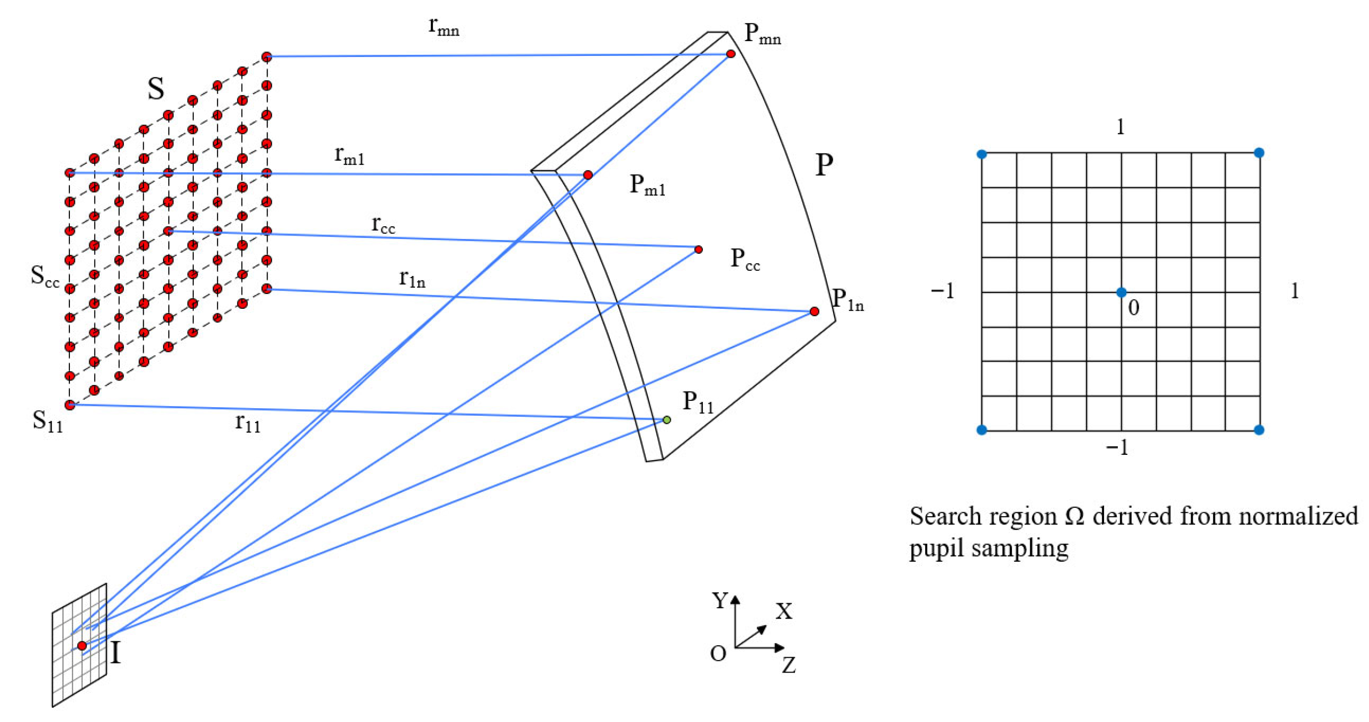
On the object surface S , m × n feature points are uniformly sampled, and m × n rays are emitted in parallel from these points. The object surface S , the ideal image point I , and the initial point P 11 on surface P are known. Among them, the positions of P 11 and I are selected randomly. Assuming the coordinates of any point on surface P are x p i j , y p i j , z p i j , and the coordinates of any point on object surface S and image point I are x s i j , y s i j , z s i j and 0 , y , z , respectively. Then, the unit directional vectors of the incident and outgoing rays at point P 11 are denoted by I 11 = S 11 P 11 S 11 P 11 and O 11 = P 11 I P 11 I , respectively. The unit normal vector at point P 11 is
N 11 = O 11 I 11 O 11 I 11
The coordinates of the second sampling point P 12 , which can be obtained by the intersection of the second sampling light ray r 12 with the tangent plane at point P 11 , are as follows:
x p 12 , y p 12 , z p 12 = x s 12 , y s 12 , z s 12 + N 11 x p 11 x s 12 , y p 11 y s 12 , z p 11 z s 12 N 11 r 12 r 12
After obtaining point P 12 , the tangent plane of this point can be determined based on the incident ray vector S 12 P 12 and the outgoing ray vector P 12 I 12 . The intersection of this tangent plane with the third sampling light ray r 13 gives point P 13 ; the fourth sampling light ray r 14 intersects with the tangent plane at point P 13 to obtain point P 14 . This process continues, and coordinates of adjacent points are obtained [26].
P 1 j = S 1 j + N 1 j 1 P 1 j 1 S 1 j N 1 j 1 r 1 j r 1 j
In the equation, r 1 j = S 1 j P 1 j / S 1 j P 1 j represents the incident unit vector of the sampling light ray, where 2 < j < n. The data points obtained from the first row form a curve, which is the seed curve in the seed curve expansion method. The subsequent data points on the curve are obtained by finding the intersection points of the feature ray with all the data points on the previous curve’s tangent plane. This process is the seed curve expansion process. By repeating this process, all the data points of the freeform surface P can be obtained, as shown in Figure 1.
The obtained point cloud data is described using XY polynomials for surface representation, which is most suitable for manufacturing due to its consistency with numerical control machining expressions. The expression is as follows [28]:
z = c ( x 2 + y 2 ) 1 + 1 ( 1 + k ) c 2 ( x 2 + y 2 ) + A 2 y + A 3 x 2 + A 5 y 2 + A 7 x 2 y + A 9 y 3 + A 10 x 4 + A 12 x 2 y 2 + A 14 y 4 + A 16 x 4 y + A 18 x 2 y 3 + A 20 y 5
where c represents the curvature of the freeform surface, k is the conic coefficient, and A i are the coefficients of the XY polynomials. The SCE algorithm fits the point cloud data into a freeform surface by only considering the fitting of the data point positions.

2.2. Single-Field Off-Axis Single-Reflective Freeform Construction Using the SI-SCE Algorithm Based on Ray Tracing and Fermat’s Principle

2.2.1. Single-Field Off-Axis Single-Reflective Freeform Construction with Infinite Object Distance

For a single spherical mirror, given the F-number and the aperture D, the focal length f is defined as f = F × D . The radius of curvature of the mirror is R = 2 × f [29]. An initial spherical system can be established by applying an appropriate decenter and tilt.
Before determining the positions of the initial point P 11 and the ideal image point I , it is necessary to note that the freeform system is symmetric about the YOZ plane. Thus, the surface position can be described using only Y decenter, Z decenter, and tilt angle α . The initial point P 11 x 11 , y 11 , z 11 and the surface center point P c c are defined as points on the propagation paths of the first sampling ray r 11 and the central sampling ray r c c , respectively, whose coordinates can be obtained by ray tracing. Once the decenter values and the tilt angle of the spherical surface are specified, the unit normal vector n c c at P c c can also be determined by ray tracing.
Under ideal conditions, sampling rays from different pupil positions should converge precisely at the ideal image point I after reflection from the freeform surface. Let the pupil coordinate be u , v and the image plane coordinate be y , z . The optical path length O P L u , v of the chief ray at the field center is taken as the reference. In the absence of aberration, the following condition must be satisfied:
O P L u , v = O P L 0 , u , v P
Here, P denotes the pupil region, and O P L 0 is a constant optical path length.
However, in a practical optical system, rays from different pupil points do not converge exactly because of aberrations. To address the instability of the initial conditions caused by the random selection of the initial point and the ideal image point in the traditional SCE algorithm, this work introduces the Stable Initialization Seed Curve Extension (SI-SCE) method. The approach constrains the search range of the ideal image point through normalized pupil sampling.
The specific steps are as follows:
As shown in Figure 2, five representative sampling points are selected on the pupil plane.
u , v { ( 1 , 1 ) , ( 1 , 1 ) , ( 1 , 1 ) , 1 , 1 , 0 , 0 }
The corresponding image plane coordinates are obtained by ray tracing:
y i , z i , i = 1 , , 5
These coordinates form a constraint region   Ω R 2 , which defines the possible range of the ideal image point   ( y , z ) , namely
( y , z ) Ω
Within the region   Ω , a uniform grid of candidate points   y k , z k is constructed with a step size Δ . The unit normal vector n c c at the freeform surface center point is used as a geometric constraint, as follows:
n c c = O c c I c c O c c I c c
Here, O c c = P c c I P c c I , I c c = S c c P c c S c c P c c denote the unit direction vectors of the emergent and incident rays, respectively. For each candidate point, the optical path length function of the chief ray at the field center is calculated as follows:
ϕ y k , z k = O P L c c y k , z k = S cc P c c + P c c I y k , z k
The point that minimizes ϕ y k , z k is selected as the ideal image point:
y * , z * = min y k , z k Ω ϕ y k , z k
At this stage, both the initial point x 11 , y 11 , z 11 and the ideal image point   ( 0 , y , z ) have been determined. The SCE algorithm can then be used to compute all data points on the freeform surface P . To better compensate for construction errors, the original algorithm’s position-only fitting method is replaced with a method that considers both position coordinates and surface normals [30]. In this work, all subsequent data point fittings adopt this improved approach.

2.2.2. Single-Field Off-Axis Single-Reflective Freeform Construction with Finite Object Distance

Compared with the case of parallel incidence with infinite object distance, constructing the surface under finite object distance requires introducing a virtual emission surface M at the initial point P 11 x 11 , y 11 , z 11 (which serves a function similar to the reference surface in the parallel light case). Let:
M = { ( x , y , z ) z = z 11 }
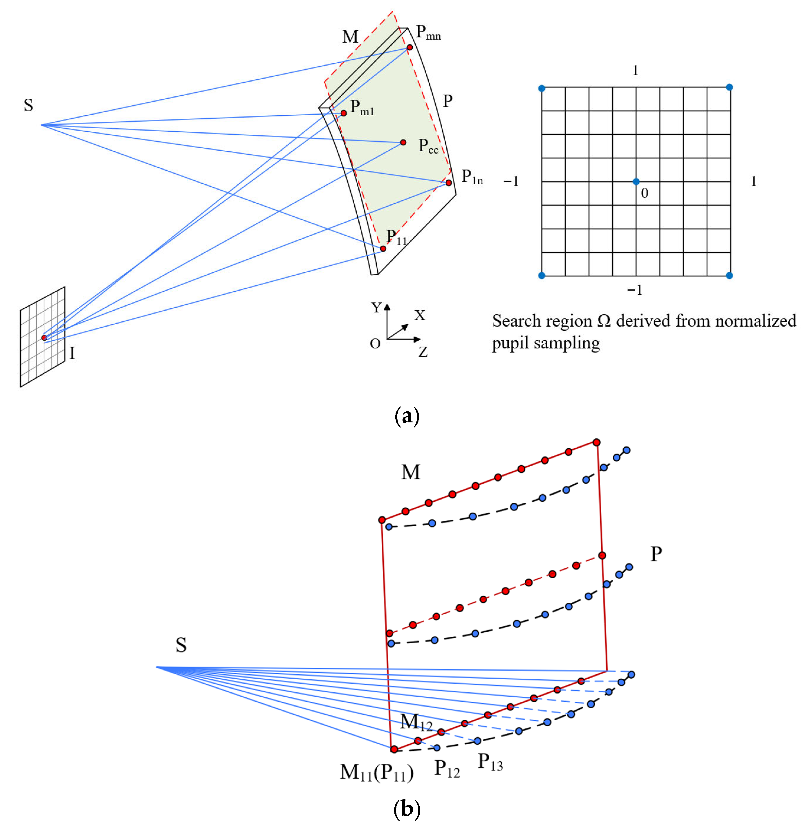
On surface M , a set of feature sampling points   M i j is selected according to an m × n uniform grid (all sampling points satisfy z M i j = z 11 ). Each incident direction is uniquely determined by the object point S (as shown in Figure 3). Let the object point be S . The unit direction vector of the incident ray passing through M i j is defined as follows:
I n i j = M i j S M i j S
In numerical implementation, if propagation from M i j to surface P is required, I n i j is used as the propagation direction. To avoid invalid incident ray direction vectors caused by M 11 coinciding with P 11 , a small axial offset along the z-axis is applied relative to P 11 during initialization, defining an initial point P 11 δ x 11 , y 11 , z 11 + δ . Accordingly, the path of the first sampling ray is defined as M 11 P 11 δ I , while other sampling rays are generated as M P I . This construction naturally degenerates to the parallel light case when the object distance approaches infinity, thereby allowing the SI-SCE initialization to accommodate both finite and infinite object distances within a unified framework.
The positions of the initial point and the ideal image point are both determined using the initial point and ideal image point calibration method in the SI-SCE algorithm, which combines ray tracing and Fermat’s principle. For the first sampling point P 11 δ , the incident ray direction vector is M 11 P 11 δ , and the emergent ray direction vector is P 11 δ I . The normal vector at this point is given by
N 11 δ = P 11 δ I M 11 P 11 δ P 11 δ I M 11 P 11 δ
Once the normal vector at the point is known, the tangent plane at that point can be determined. For the second sampling point M 12 , given the incident ray direction vector, the intersection point P 12 between the sampling ray and the tangent plane can be obtained. In the same way, all data points in this row can be determined. Subsequently, for the next row of the surface, each data point is obtained as the intersection between a characteristic ray and the tangent planes of all points in the previous row. This process is repeated until all data points are acquired.

2.2.3. Single-Field Off-Axis Single-Reflective Freeform Surface Construction

The original SCE and the proposed SI-SCE algorithms were, respectively, applied to construct single-field off-axis single-reflective freeform optical systems with both infinite and finite object distances, in order to verify the advantages of the SI-SCE method. Figure 4 shows the system layout for the infinite object distance case. As the field angle increases, the optical performance of the system gradually changes. For each field angle ( 0 ° , 2 ° , 4 ° , 6 ° , 8 ° , 10 ° ), a single-field off-axis reflective freeform optical system was independently constructed using both algorithms. The sampling interval was 0.5 mm, with a total of R = 121 × 121 = 14 , 641 sampling points. For each field, the MTF and spot diagram results of the single-field off-axis single-reflective freeform surfaces after construction are presented in Figure 5a and Figure 5b, respectively.
It can be observed that, across different field angles, the off-axis single-reflective freeform surface constructed using the SI-SCE algorithm maintains excellent imaging performance. At 30 lp/mm, both the MTF values and RMS spot diameters remain at an outstanding level. In the optical design software, the MTF is clearly close to the diffraction limit, and the RMS spot diameter is smaller than the Airy disk. Moreover, the results show no noticeable variation among different fields. In contrast, the surface constructed using the conventional SCE algorithm exhibits inferior MTF and RMS performance at 30 lp/mm, with significant fluctuations across the field. This instability arises from the arbitrary selection of initial and ideal image points.
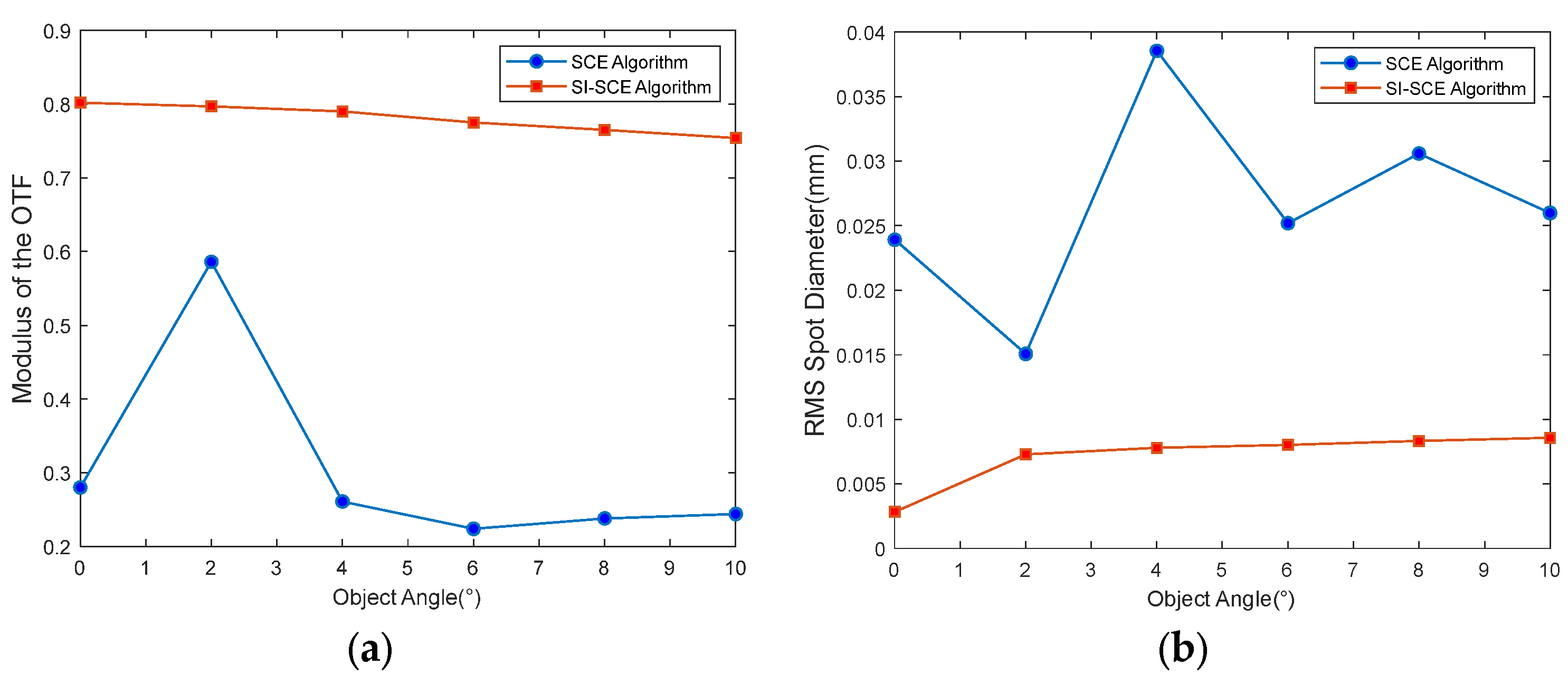
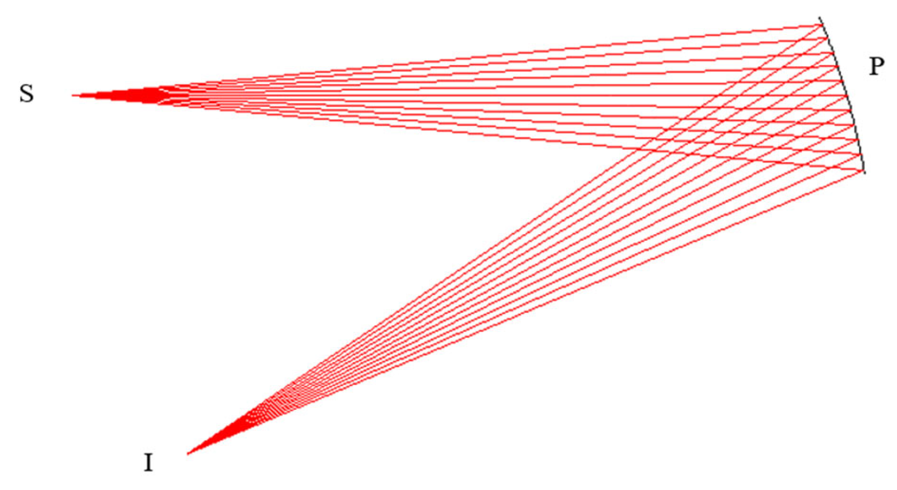
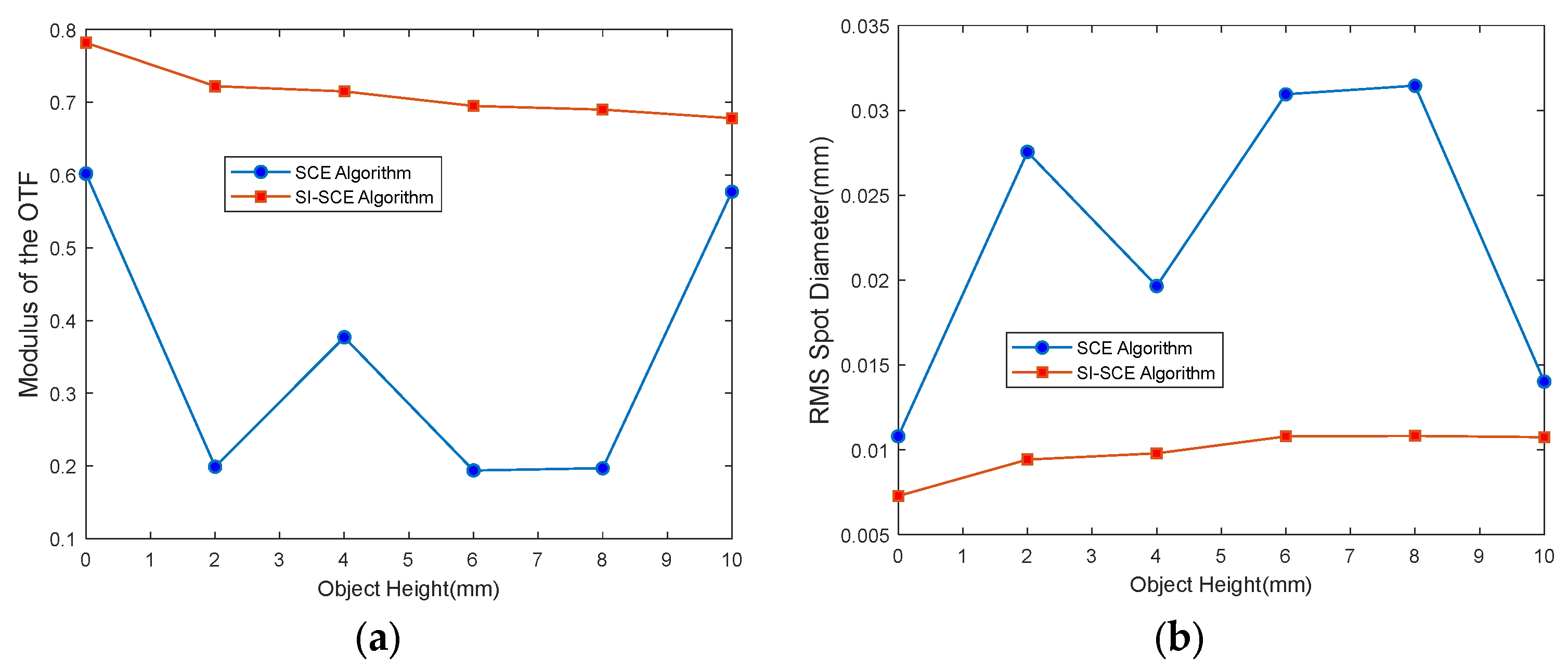
Figure 6 shows the optical layout of the system with a finite object distance. When the object heights are 0   m m ,   2   m m ,   4   m m ,   6   m m ,   8   m m ,   10   m m , both the conventional SCE algorithm and the proposed SI-SCE algorithm are used to construct single-field off-axis single-reflective freeform surfaces. The entrance pupil diameter is 40 mm, and the F-number is 2.5. The sampling interval is 0.5 mm, resulting in a total of R = 81 × 81 = 6561 sampling points. The MTF results for each field after constructing the single-field off-axis single-reflective freeform surfaces are shown in Figure 7a, and the corresponding RMS spot diameters are shown in Figure 7b.
It can be seen that, at different object heights, the off-axis single-reflective freeform surface constructed using the SI-SCE algorithm maintains very high performance at 30 lp/mm. Both the MTF values and RMS spot diameters remain excellent. In the optical design software, the MTF approaches the diffraction limit, and the RMS spot diameter is smaller than the Airy disk. No significant variation is observed across different fields. In contrast, the surface constructed by the conventional SCE algorithm shows poorer MTF and RMS performance at 30 lp/mm, with larger fluctuations among fields. This is attributed to the random selection of initial and ideal image points.
In summary, for both infinite and finite object distances, the off-axis single-reflective freeform surface was constructed using the SI-SCE and conventional SCE algorithms. The results show that the SCE algorithm produces highly random outcomes. Its performance largely depends on the selection of initial and ideal image points, often requiring multiple manual attempts to determine the “optimal” positions, which is time-consuming. In contrast, the SI-SCE algorithm employs a fully automated calibration method based on ray tracing and Fermat’s principle. This approach determines the optimal initial and ideal image points within the calibration range in a single calculation, significantly reducing construction time. Furthermore, the automated calibration method for determining initial and ideal image points, based on ray tracing and Fermat’s principle within the SI-SCE algorithm, is not limited to the SCE algorithm. It can also be applied to the DSCE and OSCE algorithms. However, with this calibration method, the construction of multiple freeform surfaces can be accomplished solely using the SI-SCE algorithm. This removes the need to apply DSCE or OSCE with increased sampling points to reduce construction errors. As a result, the approach significantly improves computational efficiency and simplifies algorithm implementation.

2.3. Construction of Single-Field Off-Axis Multi-Reflective Freeform Surface Systems Under Application-Oriented and System Parameter Constraints

The original SCE algorithm does not impose constraints on the system parameters during construction. As a result, although the constructed system may exhibit good imaging quality, its optical performance can deviate from the design specifications, making it unsuitable for subsequent optimization. This paper presents a method for constructing a single-field off-axis multi-mirror freeform system under application-specific and system parameter constraints, based on the single-field off-axis single-mirror freeform SI-SCE algorithm described in Section 2.2. A coaxial spherical system, which meets the design requirements, is first obtained through numerical calculation, and then, off-axis processing is applied. By adjusting the decenter and tilt of the spherical mirrors, the system is designed to ensure that all rays are unobstructed across the full field of view while meeting the desired shape and size constraints. Although the construction is performed for a single field, the resulting initial structure can be directly applied to multiple fields. On this basis, the SI-SCE algorithm is used to accurately determine the initial points and ideal image points of each surface, thus completing the initial structure in a single step.
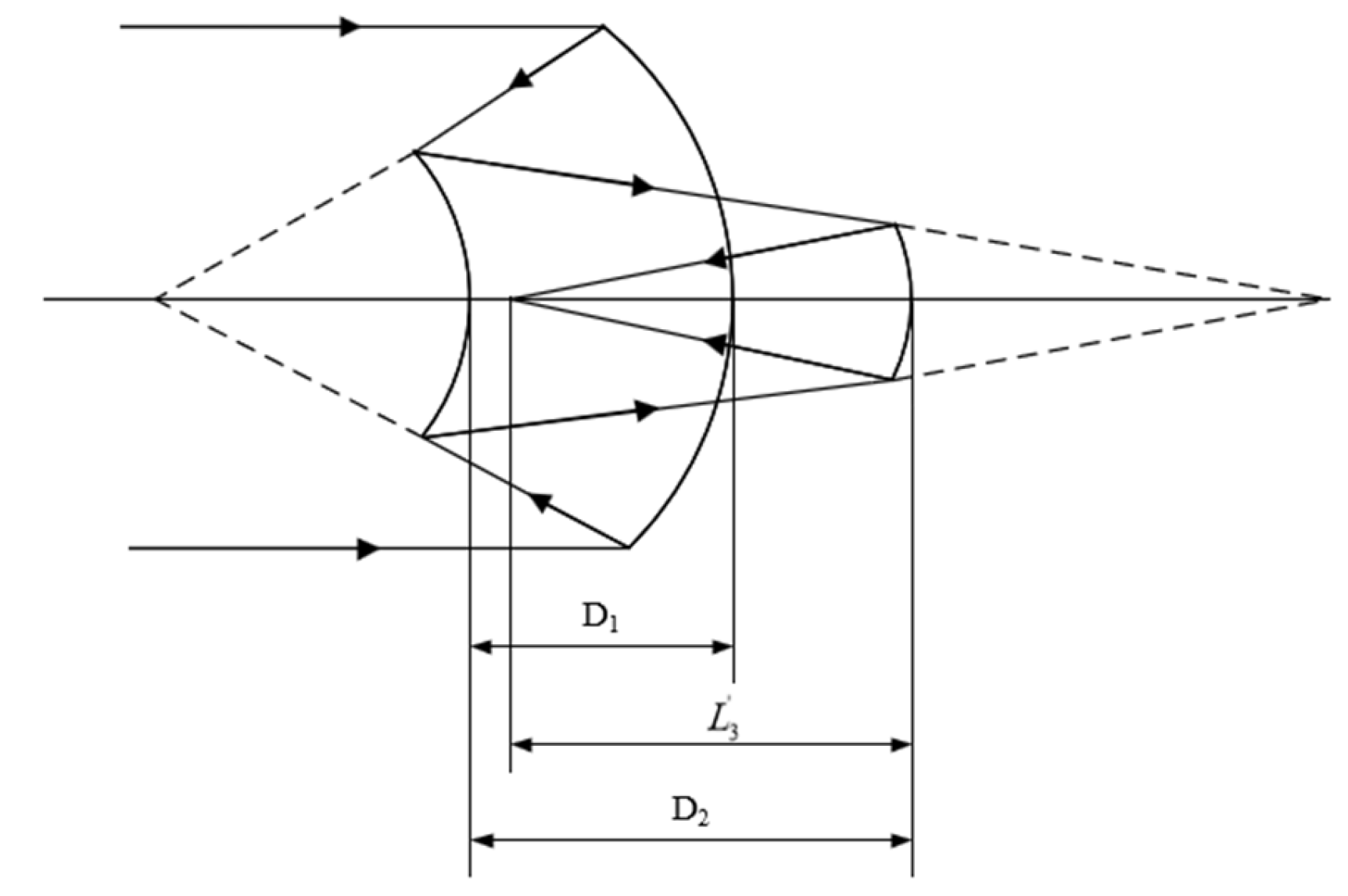
To ensure the constructed system meets the design requirements for aperture, focal length, and overall dimensions, the coaxial initial spherical system adopts the coaxial three-mirror configuration shown in Figure 8 [31]. Given the known distances D 1 , D 2 , L 3 and focal length f , the curvature radius of each mirror can be calculated using the following procedure.
α 1 is the obstruction ratio of the secondary mirror to the primary mirror, α 2 is the obstruction ratio of the tertiary mirror to the secondary mirror, β 1 and β 2 are the magnification ratios of the secondary mirror and tertiary mirror, respectively. D 1 is the distance between the primary mirror and the secondary mirror, D 2 is the distance between the secondary mirror and the tertiary mirror, L 3 is the distance from the tertiary mirror to the image plane, R 1 , R 2 and R 3 are the radii of curvature of the three mirrors, respectively.
The curvature radii R 1 , R 2 and R 3 of the three mirrors are as follows:
R 1 = 2 β 1 β 2 f , R 2 = 2 α 1 β 2 1 + β 1 f , R 3 = 2 α 1 α 2 1 + β 2 f
The distances between the three mirrors are as follows:
D 1 = R 1 2 1 α 1 f = 1 α 1 β 1 β 2 f , D 2 = R 1 2 α 1 β 1 1 α 2 f = α 1 1 α 2 β 2 f , L 3 = α 1 α 2 f
It is required that the image plane be flat, S I V = 0
β 1 β 2 β 2 1 + β 1 α 1 + 1 + β 2 α 1 α 2 = 0
Then, by applying the condition of a flat image plane (Equation (9)), the equation is rearranged into a quadratic equation in terms of α 1 .
A α 1 2 + B α 1 + C = 0
In the equation,
A = f 2 D 2 L 3 f D 1 B = 2 f 1 D 1 1 D 2 + f L 3 C = L 3 D 2 f D 1
Considering the obstruction ratio, let α 1 be positive. Substituting α 1 back into Equation (15) yields R 1 , R 2 and R 3 . After off-axis treatment of the aperture or field in the designed coaxial three-mirror spherical system, appropriate constraints are applied to control the decenter and tilt of each surface while maintaining the curvature and inter-mirror distances. This ensures obstruction-free performance across all field rays. Since the focal length of each mirror remains unchanged after off-axis processing, the ideal image point positions for constructing freeform surfaces can be approximately determined from each spherical surface during the construction process.
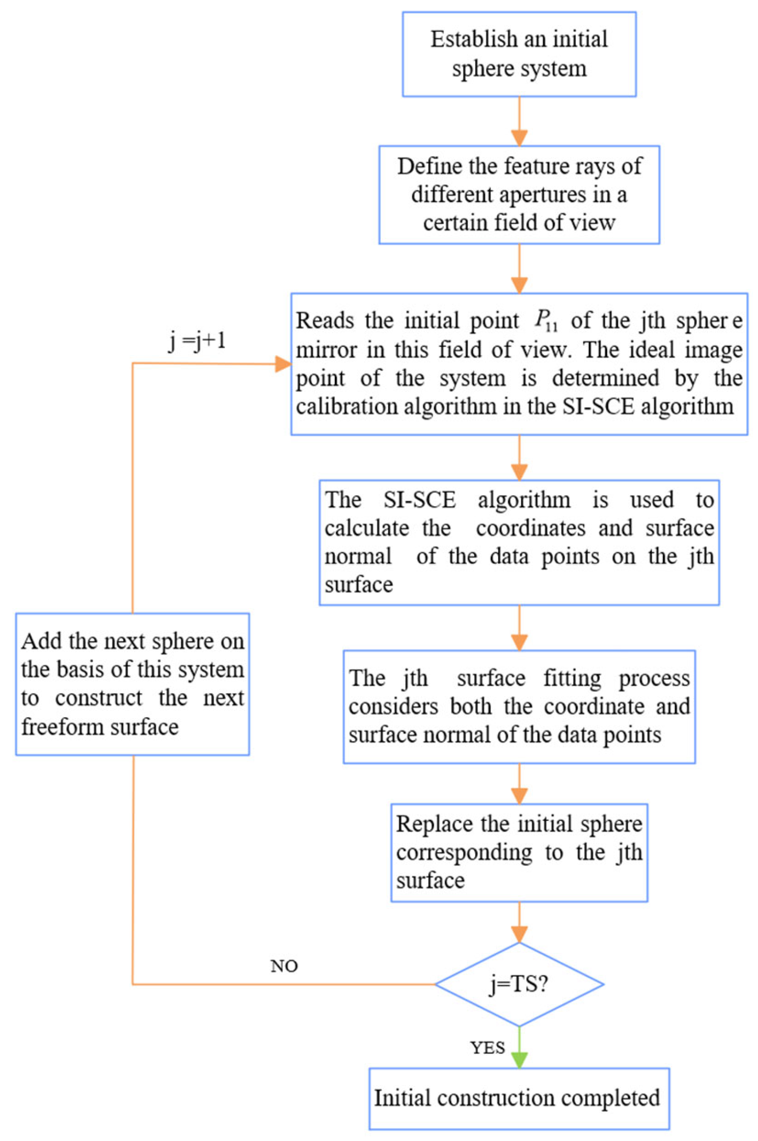
The Initial point P 11 corresponds to the intersection coordinates of the feature ray r 11 with the spherical surface. To determine the precise location of the ideal image point, we employ a method combining ray tracing and Fermat’s principle within the SI-SCE algorithm, optimizing the chief ray’s optical path to a minimum within a constrained region. The detailed construction process for the off-axis, multi-mirror freeform optical system with a single field is illustrated in Figure 9.
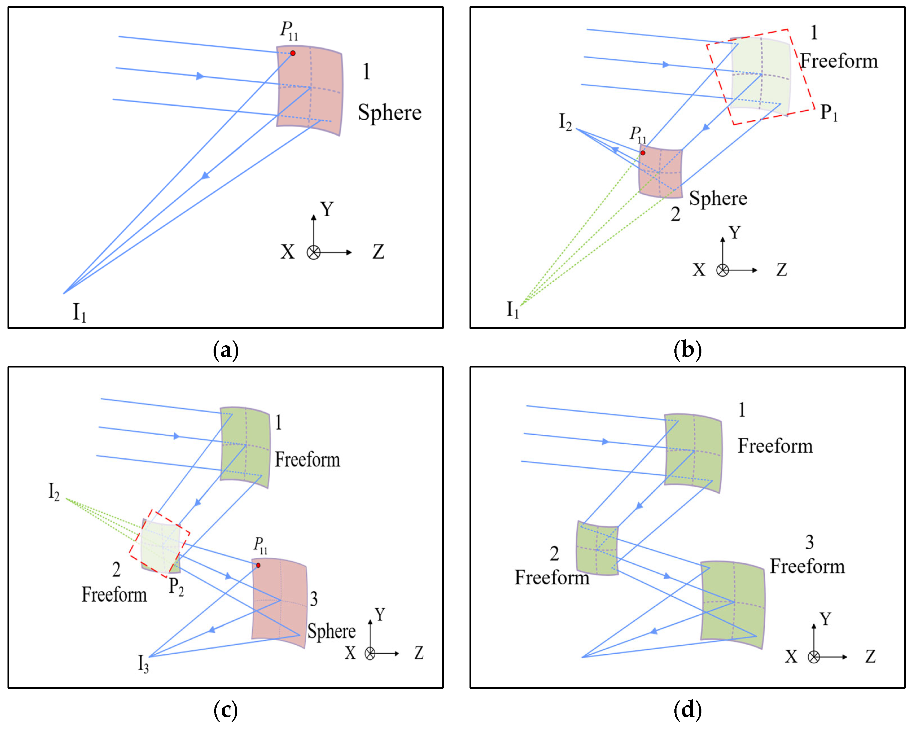
At the initial stage of construction, it is necessary to make sure that the center of each freeform surface during construction is the same as the center of the spherical surface after the coaxial three-mirror spherical surface system is off-axis processed. First, the SI-SCE algorithm is used to obtain the initial point P 11 required for the construction of freeform surface 1 and the ideal image point I 1 corresponding to the system at this time from sphere surface 1, and the construction of freeform surface 1 is carried out based on this, and the constructed freeform surface 1 replaces sphere 1. The construction principle is shown in Figure 10a. Next, freeform surface 1 and sphere surface 2 are used to prepare for the construction of freeform surface 2. A virtual surface P 1 is placed behind freeform surface 1. This surface is perpendicular to the direction of the chief ray emerging from freeform surface 1 and serves as an equivalent object plane at infinity. The SI-SCE algorithm is then applied again to determine the initial point P 11 required for constructing freeform surface 2, along with the corresponding ideal image point I 2 . Based on this, freeform surface 2 is constructed and used to replace sphere surface 2. The construction principle is shown in Figure 10b. Following the above strategy, the third freeform surface is constructed using the same “freeform surface + sphere surface” combination. The SI-SCE algorithm is employed to guide this process, as illustrated in Figure 10c. This procedure is repeated iteratively until all freeform surfaces are constructed, as shown in Figure 10d. The detailed construction of the pseudocode is provided in Appendix A.

3. Design of an Off-Axis Three-Mirror Freeform System Using the SI-SCE Algorithm

The off-axis three-mirror system features a complex structure, asymmetric optical path, and high degrees of freedom. It is highly sensitive to both design and manufacturing errors. Traditional spherical or aspheric designs are often insufficient to correct the high-order aberrations commonly found in off-axis systems, especially under wide field-of-view conditions. In contrast, freeform surfaces offer stronger aberration correction capabilities. They can significantly reduce high-order off-axis aberrations such as coma and astigmatism, making it easier to achieve wide field of view and high imaging quality. Therefore, this paper selects a freeform off-axis three-mirror imaging system with a medium F-number and a rectangular field of view as the study model. This system is used to verify the effectiveness of the proposed SI-SCE algorithm in addressing the limitations of the existing SCE method. It also serves to further evaluate the algorithm’s capability to construct the initial structure of an off-axis multi-mirror freeform system with high accuracy under a single-field condition. The specifications of the optical system are listed in Table 1.
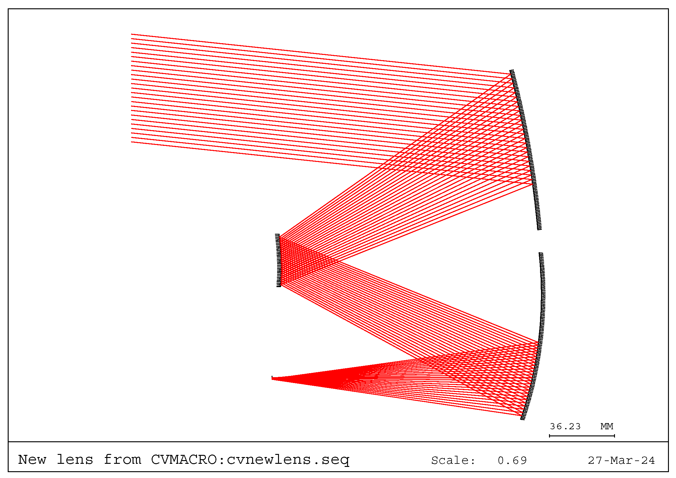
An initial spherical system with decenter and tilt was first established to eliminate optical blockage, as shown in Figure 11. The secondary mirror serves as the aperture stop. In order to make the final initial structure suitable for the 6 ° × 6 ° rectangular field of view required by the design, the spherical system should eliminate obstruction of all field-of-view rays, and only display the central field of view 0 ° , 6 ° . The system uses an offset 6 ° × 6 ° field of view in the vertical direction, with a single-field off-axis three-mirror system constructed with a center field. The entrance pupil diameter is 60 mm, the sampling point spacing is 0.5 mm, and a total of R = 121 × 121 = 14 , 641 points are sampled.
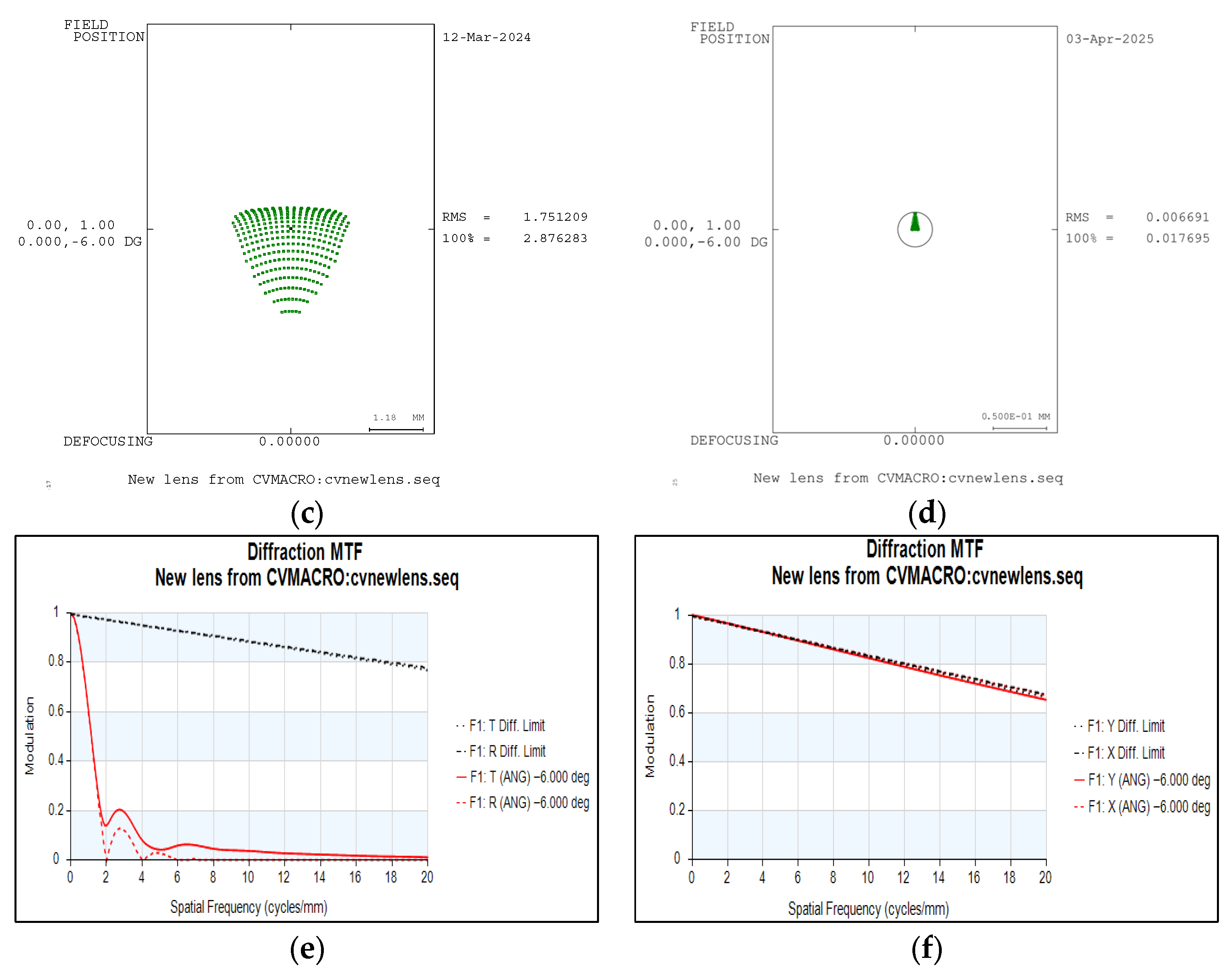
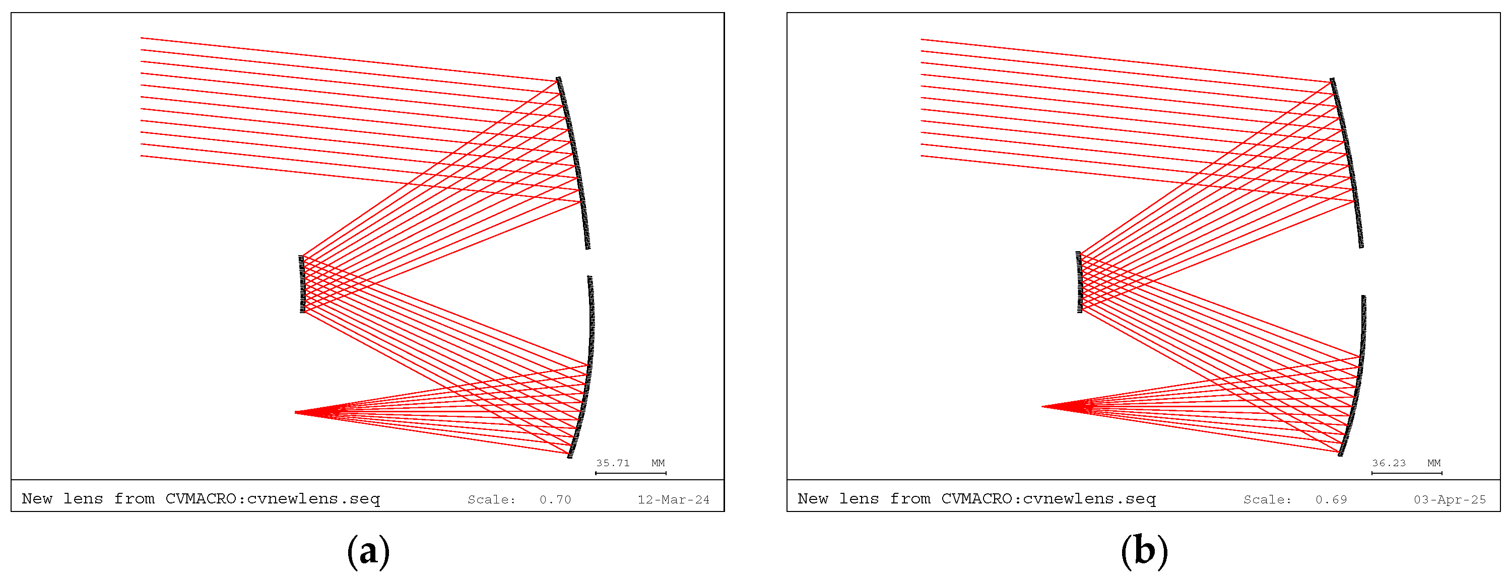
The figures below show the optical system and corresponding MTF and spot diagrams before and after the sequential construction of three freeform surfaces. As shown in Figure 12, before constructing the first freeform surface, the system contains only one spherical mirror, with an RMS spot size of 1.7512 mm. At this stage, the MTF is too low to be read accurately. After replacing the spherical surface with the constructed Freeform1, the RMS spot size drops significantly to 0.006691 mm. The MTF exceeds 0.7 at 20 lp/mm, approaching the diffraction limit. This result confirms the effectiveness of the SI-SCE algorithm in calibrating the initial point and ideal image point, and in constructing the freeform surface under infinite object distance conditions.
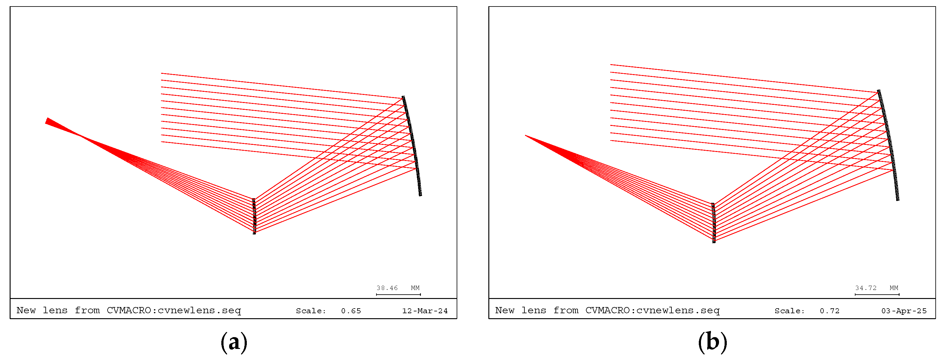
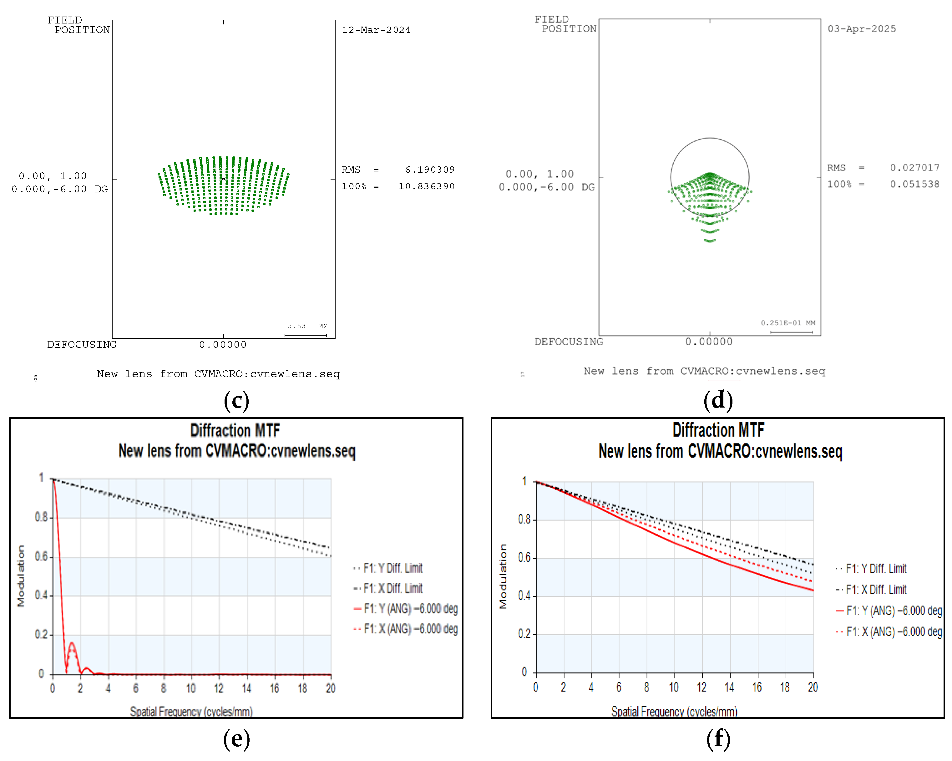
As shown in Figure 13, before constructing the second freeform surface, the system consisting of Freeform 1 and Sphere 2 shows a large visible spot size in the layout. The RMS value at this stage is 6.19 mm, and the MTF is nearly undetectable. After replacing Sphere 2 with the constructed Freeform 2, the RMS drops significantly to 0.027 mm. The MTF at 20 lp/mm exceeds 0.4, showing a clear improvement, though still below the diffraction limit. This result demonstrates the effectiveness of the SI-SCE algorithm in calibrating the initial point and ideal image point, and in constructing the freeform surface under finite object distance conditions.
As shown in Figure 14, before constructing the third freeform surface, the system consisting of Freeform 1, Freeform 2, and Sphere 3 appears to have a small spot size, but the RMS value is 2.045 mm. The MTF is very low, around 0.1, after 4 lp/mm. After replacing Sphere 3 with the constructed Freeform 3, the RMS decreases significantly to 0.01382 mm. The MTF at 20 lp/mm exceeds 0.7, approaching the diffraction limit. This process not only verifies the effectiveness of the SI-SCE algorithm in calibrating the initial point and ideal image point, and in constructing the freeform surface under finite object distance conditions but also confirms that the system parameters meet the design specifications after the completion of the off-axis multi-mirror freeform surface construction.
During the construction of this off-axis three-mirror freeform surface, the coordinates of the initial points and ideal image points for each freeform surface, as solved by the SI-SCE algorithm, are shown in Table 2 below.
The above results show that during the construction of each freeform surface, the rays are effectively directed to the intended position (i.e., the ideal image point for each freeform surface). Although the initial structure generated in this paper is designed for a single field of view, it can serve as a starting point for subsequent optimization, as it approaches the diffraction limit.
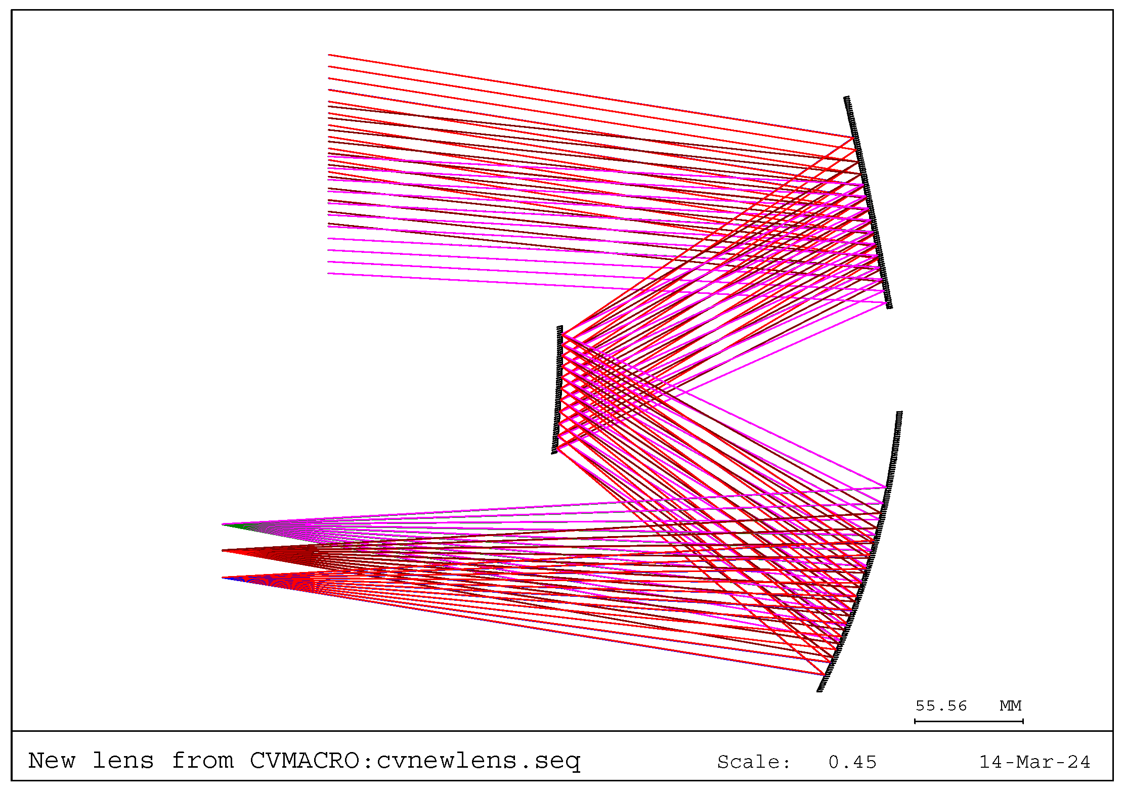
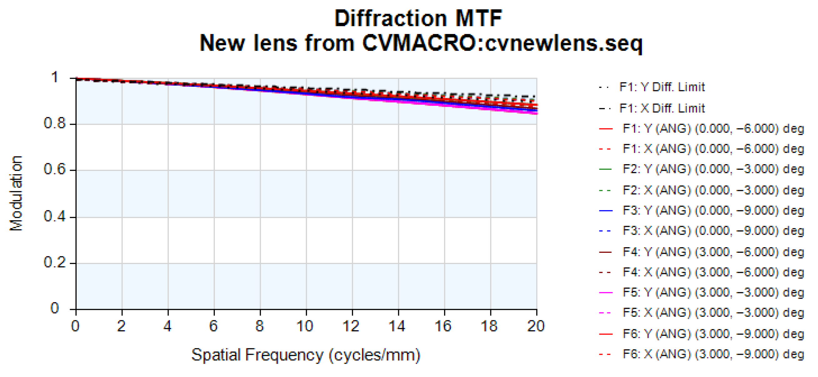
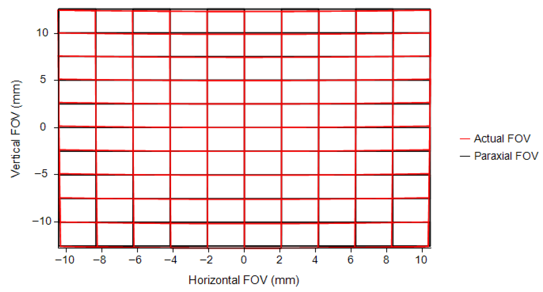
By subsequent optimization of the starting point, as the system is symmetric about the YOZ plane, only half of the full field needs to be set. Six biased fields were used, namely (0°, −6°), (0°, −3°), (0°, −9°), (3°, −6°), (3°, −3°), and (3°, −9°), to quickly obtain the final freeform off-axis three-mirror system. The system layout is shown in Figure 15. Compared to the initial structure, slight changes are observed in the curvature and decenter tilt of the final optimized system, but the overall structure and direction of light rays remain largely unchanged, which is an acceptable and normal phenomenon in optical design. The optimized off-axis three-mirror freeform surfaces are represented using XY polynomials. In this design, fifth-order XY polynomial is employed, and the corresponding coefficients are listed in Table 3 below. The MTF plot of the final system is depicted in Figure 16, demonstrating diffraction performance at Visible–NIR wavelengths. The MTF (greater than 0.8 at 20 lp/mm) approaches the diffraction limit. Figure 17 displays the distortion grid, with maximum grid distortion less than 2%.
When it comes to designing high-performance optical systems (such as those with large fields of view or small F-numbers), starting directly from spherical surfaces and relying solely on optical design software often yields suboptimal results and requires extensive design experience from the designer. In the design examples, we attempted to optimize the initial spherical system directly using optical design software. Even experienced designers require a significant amount of time to achieve satisfactory design results. However, with the construction method proposed in this paper, a good initial structure with freeform surfaces can be obtained from spherical surfaces based on given design requirements. This initial structure already meets the requirements for aperture, focal length, and size limitations, providing excellent imaging quality close to the diffraction limit in a single field of view, while also achieving good focusing for rays of different apertures in other fields of view. Although subsequent optimization is still required using optical design software, in this design example, the process from starting point to final design becomes much easier, significantly reducing the threshold of design experience required. The discussion above validates the feasibility of the design method proposed in this paper.

4. Conclusions

The SI-SCE algorithm proposed in this paper achieves key improvements over the existing SCE algorithm. By introducing an accurate initial point and ideal image point calibration method based on ray tracing and Fermat’s principle, the algorithm effectively overcomes the randomness in selecting initial conditions found in traditional methods. For complex scenarios with non-parallel light incidence at finite object distances, an auxiliary interface setup strategy for the freeform surface pre-construction phase is proposed, significantly improving the algorithm’s adaptability and construction accuracy. Additionally, a system parameter constraint method is employed to directly construct an off-axis multi-mirror freeform system that meets the specified entrance pupil diameter, focal length, and structural size requirements. The feasibility and advantages of this design method are verified by designing a freeform off-axis three-mirror system with a rectangular field of view and a medium F-number. The final system has an F/3.4, 60 mm entrance pupil diameter, and a field of view of 6 ° × 6 ° . The freeform surfaces in the system are represented by XY polynomials and achieve diffraction-limited performance in the Visible–NIR 0.38 2   μ m wavelength range, verifying the effectiveness and practicality of the algorithm in constructing the initial structure of off-axis multi-mirror freeform optical systems.

Author Contributions

Supervision, Y.H.; methodology, J.H.; writing—original draft preparation, J.H.; writing—review and editing, J.H. All authors have read and agreed to the published version of the manuscript.

Funding

This research was funded by Jilin Provincial Natural Science Foundation, grant number 20240101360JC. This research was funded by Scientific Research Project of the Jilin Provincial Department of Education, grant number JJKH20250494BS.

Data Availability Statement

The data presented in this study are available on request from the corresponding author.

Conflicts of Interest

The authors declare no conflicts of interest.

Appendix A

Algorithm A1: Single-field off-axis multi-mirror freeform surface construction algorithm
  • Input: Field parameters, mirror curvature radius R, decenter and tilt parameters, number of sampling points n
  • Output: Initial point, ideal image point coordinates, data point coordinates and normal vectors on the freeform surface, fitted freeform surface coefficients
  1:
Step 1: Establish the initial spherical system
  2:
Compute the coaxial three-mirror configuration using analytical geometry.
  3:
Given the mirror spacing and focal length, determine the curvature radius of each mirror.
  4:
Apply decentering and tilting to each mirror to satisfy the system’s physical aperture and avoid ray blockage over the full field of view.
  5:
Step 2: Initialize CodeV and load the optical model
  6:
Use MATLAB via the COM interface to execute CodeV commands and initialize the optical system.
  7:
Define system parameters including aperture, spacing, curvature, tilt, and decenter values.
  8:
Insert the initial surface S and the base spherical surface P .
  9:
Specify pupil sampling points for subsequent ray tracing.
10:
Step 3: Determine the ideal image point
11:
The initial surface point P 11 ( x 11 , y 11 , z 11 ) is defined as the intersection between the first sampled ray r 11 and the spherical surface.
12:
Select five representative sampling points on the pupil plane:
13:
( u , v ) { ( 1 , 1 ) , ( 1 , 1 ) , ( 1 , 1 ) , ( 1 , 1 ) , ( 0 , 0 ) }
14:
Perform ray tracing to obtain the corresponding image plane coordinates:
15:
( y i , z i ) , i = 1 , , 5 .
16:
These coordinates define a constraint region Ω 2 that limits the possible range of the ideal image point ( y * , z * ) .
17:
( y * , z * ) Ω
18:
Construct a uniform grid of candidate points within Ω with a step size Δ , using the surface normal at the optical center n c c as a geometric constraint:
19:
n c c = O c c I c c | O c c I c c |
20:
Here, O c c = P c c I | P c c I | and I c c = S c c P c c | S c c P c c | denote the unit direction vectors of the exiting and incident rays, respectively.
21:
For each candidate point, compute the optical path function of the chief ray:
22:
ϕ ( y k , z k ) = O P L c c ( y k , z k ) = | S c c P c c | + | P c c I ( y k , z k ) |
23:
The candidate point that minimizes ϕ ( y k , z k ) is taken as the ideal image point I i .
24:
Step 4: Calculate freeform surface data points and normals using the SCE algorithm
25:
for each seed curve i = 1 : m  do
26:
  if  i = 1  then
27:
   With the known initial point P 11 and ideal image point I i , compute the corresponding surface normal.
28:
   The next point along the curve is defined as the intersection between the characteristic ray and the tangent plane of the previous point, forming the complete seed curve.
29:
  end if
30:
  For subsequent curves, determine each data point as the intersection between the characteristic ray and the tangent planes defined by data points of the preceding curve.
31:
  Repeat until all data points on the freeform surface P are obtained.
32:
end for
33:
Step 5: Fit the freeform surface
34:
Fit the point cloud into a continuous freeform surface by simultaneously considering both position coordinates and surface normals.
35:
Write the fitted surface coefficients into CodeV and update the optical system accordingly.
36:
Step 6: Construct subsequent freeform mirrors
37:
Repeat Steps 2–5 until all reflective surfaces in the optical system are constructed.

References

  1. Jia, X.; Jia, H. Off-axis freeform optical design for large curved field of view imaging. Appl. Opt. 2024, 63, 8152–8163. [Google Scholar] [CrossRef]
  2. Wang, Y.; Yang, T.; Lyu, X.; Cheng, D.; Wang, Y. Ultra-simplified and low-cost head-up display system enabled by freeform holographic element. Opt. Laser Technol. 2024, 178, 111253. [Google Scholar] [CrossRef]
  3. Chen, X.; Hu, L.; Liu, J.; Wang, C.; Bai, C.; Zheng, Y.; Qin, Y.; Yang, H.; Jiang, P. Design of a compact off-axis two-mirror freeform optical antenna for shaping and transmitting an elliptical beam emitted by laser diode. Appl. Opt. 2023, 63, 239–248. [Google Scholar] [CrossRef]
  4. Zhao, G.; Zhu, J. Design of off-axis reflective dual-channel zoom freeform optical systems. Opt. Commun. 2025, 574, 131079. [Google Scholar] [CrossRef]
  5. Kumar, S.; Zhong, W.; Williamson, J.; Kumar, P.; Furness, T.; Lou, S.; Zeng, W.; Jiang, X. Design, fabrication, and testing of freeform mirror-based head-up display system. Opt. Laser Technol. 2025, 186, 112653. [Google Scholar] [CrossRef]
  6. Zhao, G.; Zhu, J. Off-axis zoom optical systems based on mirror rotation and their design method. Opt. Laser Technol. 2024, 177, 111031. [Google Scholar] [CrossRef]
  7. Yang, T.; Zhu, J.; Wu, X.; Jin, G. Direct design of freeform surfaces and freeform imaging systems with a point-by-point three-dimensional construction-iteration method. Opt. Express 2015, 23, 10233–10246. [Google Scholar] [CrossRef]
  8. Yu, B.; Tian, Z.; Su, D.; Sui, Y.; Yang, H. Design and engineering verification of an ultrashort throw ratio projection system with a freeform mirror. Appl. Opt. 2019, 58, 3575–3581. [Google Scholar] [CrossRef]
  9. Liu, X.; Zhu, J. Design method of freeform off-axis multi-mirror optical systems. Photonics 2022, 9, 534. [Google Scholar] [CrossRef]
  10. Volatier, J.-B.; Druart, G. Differential method for freeform optics applied to two-mirror off-axis telescope design. Opt. Lett. 2019, 44, 1174–1177. [Google Scholar] [CrossRef]
  11. Duerr, F.; Benítez, P.; Miñano, J.C.; Meuret, Y.; Thienpont, H. Analytic design method for optimal imaging: Coupling three ray sets using two free-form lens profiles. Opt. Express 2012, 20, 5576–5585. [Google Scholar] [CrossRef]
  12. Duerr, F.; Benítez, P.; Miñano, J.C.; Meuret, Y.; Thienpont, H. Analytic free-form lens design in 3D: Coupling three ray sets using two lens surfaces. Opt. Express 2012, 20, 10839–10846. [Google Scholar] [CrossRef] [PubMed]
  13. Nie, Y.; Thienpont, H.; Duerr, F. Multi-fields direct design approach in 3D: Calculating a two-surface freeform lens with an entrance pupil for line imaging systems. Opt. Express 2015, 23, 34042–34054. [Google Scholar] [CrossRef] [PubMed]
  14. Nie, Y.; Mohedano, R.; Benítez, P.; Chaves, J.; Miñano, J.C.; Thienpont, H.; Duerr, F. Multifield direct design method for ultrashort throw ratio projection optics with two tailored mirrors. Appl. Opt. 2016, 55, 3794–3800. [Google Scholar] [CrossRef] [PubMed]
  15. Cheng, D.; Wang, Y.; Hua, H. Free form optical system design with differential equations. In Optical Design and Testing IV (SPIE2010); Photonics Asia: Beijing, China, 2010; pp. 190–197. [Google Scholar]
  16. Hicks, R.A. Controlling a ray bundle with a free-form reflector. Opt. Lett. 2008, 33, 1672–1674. [Google Scholar] [CrossRef]
  17. Hicks, R.A.; Croke, C. Designing coupled free-form surfaces. J. Opt. Soc. Am. A 2010, 27, 2132–2137. [Google Scholar] [CrossRef]
  18. Pan, H.; Su, Z.; Zhang, Y.; Wu, T. Construct freeform surface directly in an initial layout of an off-axis reflective image system by seed curve extension and simulated annealing algorithm. J. Eur. Opt. Soc.-Rapid Publ. 2020, 16, 9. [Google Scholar] [CrossRef]
  19. Mao, B.; Yang, T.; Xu, H.; Chen, W.; Cheng, D.; Wang, Y. FreeformNet: Fast and automatic generation of multiple-solution freeform imaging systems enabled by deep learning. Photonics Res. 2023, 11, 1408–1422. [Google Scholar] [CrossRef]
  20. Nie, Y.; Zhang, J.; Su, R.; Ottevaere, H. Freeform optical system design with differentiable three-dimensional ray tracing and unsupervised learning. Opt. Express 2023, 31, 7450–7465. [Google Scholar] [CrossRef]
  21. Sun, Y.; Wei, Y.; Zhang, Y.; Zhao, J. Automated generation of easy-assembly off-axis three-mirror imaging systems based on few-shot machine learning. Appl. Opt. 2025, 64, 1068–1077. [Google Scholar] [CrossRef]
  22. Wang, L.; Qian, K.; Luo, Y. Discontinuous free-form lens design for prescribed irradiance. Appl. Opt. 2007, 46, 3716–3723. [Google Scholar] [CrossRef]
  23. Wang, K.; Liu, S.; Chen, F.; Qin, Z.; Liu, Z.; Luo, X. Freeform LED lens for rectangularly prescribed illumination. J. Opt. A Pure Appl. Opt. 2009, 11, 105501. [Google Scholar] [CrossRef]
  24. Zhang, Y.; Wang, X.; Su, Z.; Pan, H.; Chen, X.; Zhang, W. Freeform optical surface design in an off-axis reflective imaging system by a double seed curve extension algorithm. Appl. Opt. 2021, 60, 942–948. [Google Scholar] [CrossRef] [PubMed]
  25. Chen, X.; Su, Z.; Zhang, Y.; Hu, L. Design of Freeform Off-Axis Reflective Afocal Systems by Orthogonal Seed Curve Extension Algorithm. Acta Opt. Sin. 2022, 42, 0108001. [Google Scholar]
  26. Zhang, Y.; Su, Z.; Pan, H. Optical design and tolerance analysis freeform automotive head-up display. Acta Photonica Sin. 2020, 49, 922002. [Google Scholar] [CrossRef]
  27. Zhang, Y. Design of Off-Axis Freeform Reflective System by Double Seed Curve Extension Algorithm. Master’s Thesis, Jiangnan University, Wuxi, China, 17 June 2021. [Google Scholar]
  28. Yang, T.; Zhu, J.; Hou, W.; Jin, G. Design method of freeform off-axis reflective imaging systems with a direct construction process. Opt. Express 2014, 22, 9193–9205. [Google Scholar] [CrossRef]
  29. Born, M.; Wolf, E. Principles of Optics: Electromagnetic Theory of Propagation, Interference and Diffraction of Light; Cambridge University Press: Cambridge, UK, 1999. [Google Scholar]
  30. Zhu, J.; Wu, X.; Yang, T.; Jin, G. Generating optical freeform surfaces considering both coordinates and normals of discrete data points. JOSA A 2014, 31, 2401–2408. [Google Scholar] [CrossRef]
  31. Pan, J. Design, Processing, and Inspection of Optical Aspherical Surfaces; Suzhou University Press: Suzhou, China, 2004. [Google Scholar]
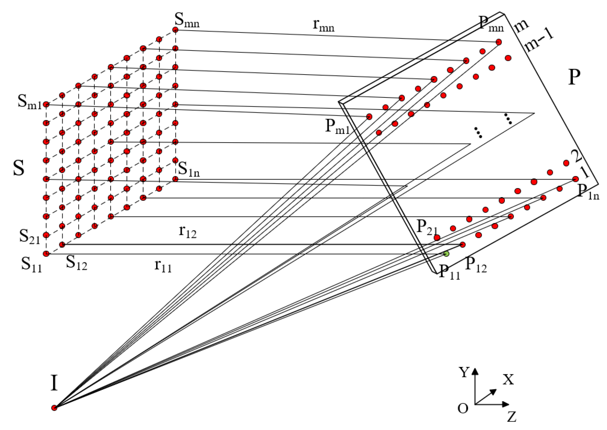
Figure 1. The schematic diagram of off-axis imaging system principle solved by SCE algorithm [27].
Photonics 12 01141 g001
Figure 2. Schematic of the SI-SCE algorithm for constructing an off-axis imaging system with infinite object distance.
Photonics 12 01141 g002
Figure 3. Schematic of the SI-SCE algorithm for solving an off-axis imaging system with finite object distance. (a) Schematic diagram. (b) Detailed solution schematic.
Photonics 12 01141 g003
Figure 4. Layout of the optical system for the infinite object distance case.
Photonics 12 01141 g004
Figure 5. Optical performance of each field after constructing single-field off-axis single-reflective freeform surfaces. (a) MTF values at 30 lp/mm for each field after construction. (b) RMS spot diameters for each field after surface construction.
Photonics 12 01141 g005
Figure 6. Optical layout of the system with a finite object distance.
Photonics 12 01141 g006
Figure 7. Optical performance of each field after constructing single-field off-axis single-reflective freeform surfaces. (a) MTF values at 30 lp/mm for each field after surface construction. (b) RMS spot diameters for each field after surface construction.
Photonics 12 01141 g007
Figure 8. Schematic diagram of coaxial three-mirror system.
Photonics 12 01141 g008
Figure 9. Flowchart of the construction process for off-axis multi-mirror freeform surfaces.
Photonics 12 01141 g009
Figure 10. Schematic of the construction process for the off-axis multi-mirror freeform surface system. (a) Schematic of the construction principle for the first freeform surface. (b) Schematic of the construction principle for the second freeform surface. (c) Schematic of the construction principle for the third freeform surface. (d) All freeform surfaces have been successfully constructed.
Photonics 12 01141 g010
Figure 11. Initial spherical system layout.
Photonics 12 01141 g011
Figure 12. System layout, spot diagram, and MTF before and after the construction of the first freeform surface. (a) Before construction. (b) After construction. (c) Before construction. (d) After construction. (e) Before construction. (f) After construction.
Photonics 12 01141 g012aPhotonics 12 01141 g012b
Figure 13. System layout, spot diagram, and MTF before and after the construction of the second freeform surface. (a) Before construction. (b) After construction. (c) Before construction. (d) After construction. (e) Before construction. (f) After construction.
Photonics 12 01141 g013aPhotonics 12 01141 g013b
Figure 14. System layout, spot diagram, and MTF before and after the construction of the third freeform surface. (a) Before construction. (b) After construction. (c) Before construction. (d) After construction. (e) Before construction. (f) After construction.
Photonics 12 01141 g014aPhotonics 12 01141 g014b
Figure 15. Final optimized system layout diagram.
Photonics 12 01141 g015
Figure 16. MTF of the final optimized system.
Photonics 12 01141 g016
Figure 17. The distortion grid of the final optimized system.
Photonics 12 01141 g017
Table 1. Specifications for freeform off-axis three-mirror design.
ParameterSpecification
Field of view (FOV) 6 ° × 6 °
F-number3.4
Entrance pupil diameter60 mm
Effective focal length204 mm
Detector pixel size 30   μ m
Wavelength Visible NIR   0.38 2   μ m
ConfigurationOff-axis three-mirror
Table 2. Coordinates of the initial point and ideal image point during the construction of off-axis three-mirror freeform surface.
Freeform SurfaceInitial PointIdeal Image Point
Freeform 1(−30, 30.757, 192.793)(0, −115.852, −37.885)
Freeform 2(−13.043, −47.323, 61.137)(0, 7.059, −86.031)
Freeform 3(−25.798, −100.861, 205.389)(0, −126.529, 43.521)
Table 3. Coefficients of the fifth-order XY polynomial for the optimized off-axis three-mirror freeform surfaces.
CoefficientPrimary MirrorSecondary MirrorTertiary Mirror
Radius−590.70901185.3700415.2863
Conic0.2268−20−0.9900
A 2 −4.4069 × 10−50.35600.3897
A 3 0.0007−0.0020−0.0027
A 5 0.0006−0.0014−0.0027
A 7 5.8921 × 10−72.1873 × 10−62.0143 × 10⁻⁶
A 9 −1.1693 × 10⁻⁶−4.6285 × 10−67.9194 × 10−7
A 10 2.2569 × 10⁻⁹−5.0074 × 10⁻⁹−4.2920 × 10⁻⁹
A 12 3.9277 × 10⁻⁹−6.770 × 10⁻⁹−1.0571 × 10⁻⁸
A 14 2.5782 × 10⁻⁹−2.7457 × 10⁻⁹−2.2173 × 10⁻⁹
A 16 2.7460 × 10−122.8341 × 10−112.1429 × 10⁻¹¹
A 18 −5.2078 × 10⁻¹²−6.4195 × 10−112.9839 × 10⁻¹¹
A 20 −3.8565 × 10⁻¹²−1.6673 × 10⁻¹¹−5.4016 × 10⁻¹²
Disclaimer/Publisher’s Note: The statements, opinions and data contained in all publications are solely those of the individual author(s) and contributor(s) and not of MDPI and/or the editor(s). MDPI and/or the editor(s) disclaim responsibility for any injury to people or property resulting from any ideas, methods, instructions or products referred to in the content.