1. Introduction
Similarly to the interferometric fiber optic gyroscope (IFOG), the resonator fiber optic gyroscope (RFOG) is a Sagnac effect–based angular velocity sensor. The concept of RFOG was first proposed by Meyer and Ezekiel in 1981 as a second generation of fiber-optic gyroscope [
1]. Hollow-core photonic-crystal fibers (HC-PCFs) exhibit significant advantages in low temperature sensitivity and suppressed nonlinear effects compared to conventional polarization-maintaining fibers (PMFs), Thus, hollow-core photonics-crystal fiber gyroscopes (HC-RFOGs) have demonstrated potential for applications in navigation and high-precision sensing [
2]. However, numerous sources of noise can degrade their performance, preventing them from fully meeting the requirements of practical applications.
Polarization noise related to temperature is considered one of the primary optical noise sources limiting the performance improvement of the HC-RFOG [
3]. The resonator consists of a coupler and a fiber loop sensitive to angular velocity. Due to the inevitable presence of alignment angle errors within the coupler, two eigenstates emerge in the resonator [
4]. Alignment angle errors, which refer to the slight angular misalignments between the polarization axes of the fiber ports and the principal axes of optical components like the PBS. The relative position of the resonance curves corresponding to these two polarization eigenstates (ESOP) shifts as the birefringence value of the fiber loop changes. When the change in the product of the birefringence and the resonator length equals an integer multiple of the optical wavelength, the relative position of the resonance curves associated with the two polarization eigenstates undergoes a periodic shift [
5]. When detecting angular velocity, the presence of these unintended polarization eigenstates leads to bias drift [
6,
7].
Many researchers have analyzed the impact of polarization noise on bias stability of the RFOG. R.J. Mears et al. from the University of Southampton compared schemes using high-birefringence fibers with different attenuation levels and proposed utilizing polarizing beam splitters external to the resonator to reduce bias drift [
8]. Graeme McRobbie et al. from the University of Strathclyde employed the Jones matrix to elucidate the generation of polarization errors in the RFOG. They proposed and validated an intra-cavity polarizer scheme to enhance the reciprocity of RFOGs [
9]. G.A. Sanders et al. from Honeywell introduced a 90-degree polarization rotation technique to decouple polarization effects from temperature variations, thereby reducing bias drift in RFOGs [
7]. Xijing Wang from the University of Tokyo proposed a dual 90-degree rotational splice method to exclusively excite a desired polarization eigenstate, though this requires stringent temperature control [
10]. Huilian et al. from Zhejiang University demonstrated that dual 90-degree rotational splicing combined with single-polarization fibers effectively mitigates polarization-induced bias noise [
11]. The research team led by Lishuang from Beihang University made foundational progress by developing and validating a single polarization resonator structure based on hollow-core photonic-crystal fiber (HCPCF) to suppress undesired polarization eigenstates. Their experimental results confirmed enhanced long-term stability, though the polarization noise suppression capability remained limited, highlighting the need for further improvements in resonator cavity polarization crosstalk suppression [
12].
In parallel with efforts to optimize resonator architecture, other research has targeted different subsystems to enhance overall performance. For instance, subsequent work by Jiao et al. focused on the light source, developing low-noise multi-frequency lasers that improved the bias stability to 5.8°/h [
13]. Others have explored advanced signal processing, with recent work demonstrating high performance through detection methods based on phase-shift keying (PSK) modulation [
14]. Furthermore, theoretical investigations continue to explore alternative device structures, such as those based on nonlinear photonic nanoring resonators, to analyze rotation sensing from a fundamental perspective [
15].
While these approaches show progress by addressing laser noise, signal processing, or alternative structures, the direct and robust suppression of polarization noise within the HC-PCF resonator itself remains a fundamental challenge and a key pathway to higher performance. This paper introduces and experimentally validates a novel high-extinction-ratio resonator (HPERR) architecture designed specifically to mitigate polarization-induced errors at their source. We first developed a rigorous mathematical model for the polarization-related bias, with simulations confirming that the HPERR design achieves high-fidelity suppression of undesired polarization states. Experimental implementation of this architecture yielded a significant, bias stability improvement in gyroscope performance from to.
The structure of this paper is arranged as follows:
Section 2 introduces the basic principles and structure of the high-extinction-ratio resonator.
Section 3 establishes a detailed mathematical model and conducts simulation analysis.
Section 4 presents the experimental setup and test results, comparing them with theoretical predictions. Finally,
Section 5 summarizes the entire paper.
This paper introduces and experimentally validates a novel high-extinction-ratio resonator (HPERR) architecture designed to mitigate polarization-induced errors. We first developed a rigorous mathematical model for the polarization-related bias, with simulations confirming that the HPERR design achieves high-fidelity suppression of undesired polarization states. Experimental implementation of this architecture yielded a significant, bias stability improvement in gyroscope performance from to .
2. Principles and Structures
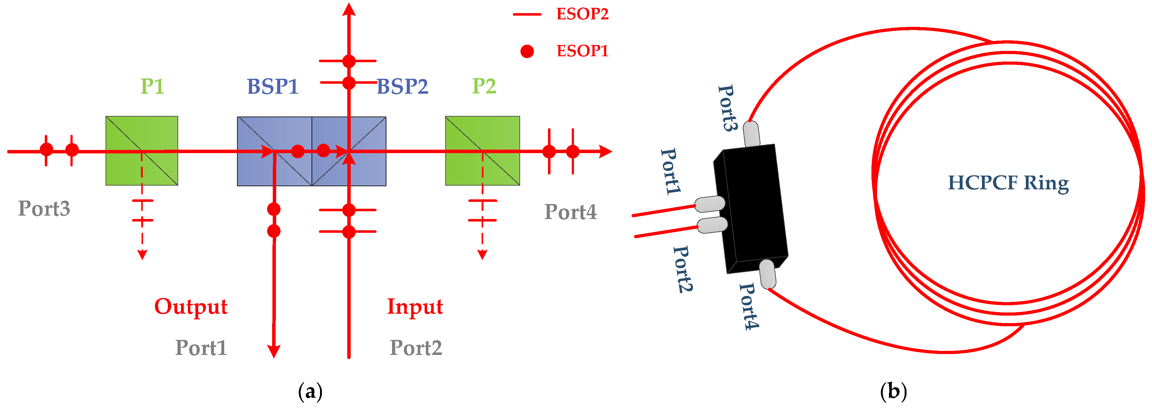
The optical polarization coupler within the HPERR is illustrated in
Figure 1a. It consists of four ports (Port 1, Port 2, Port 3, Port 4), a pair of beam splitter prisms (BSP1 and BSP2), and a pair of PBSs (P1 and P2). Counterclockwise-propagating light containing two polarization eigenstates (ESOP1 and ESOP2) enters the cavity through Port 2. Upon reaching BSP2, a portion of the light is transmitted out of the HPERR, while the remaining light is reflected toward P2. At P2, the undesired polarization eigenstate (ESOP2) is reflected and experiences first-stage attenuation, while the desired polarization eigenstate (ESOP1) passes through P2 and propagates into Port 4. The light then traverses the ring and arrives at Port 3. From Port 3, it propagates to P1. Here, ESOP2 are reflected by P1, undergoing second-stage attenuation, while the desired polarization state continues through P1 to BSP1. At BSP1, a fraction of the light is reflected toward Port 1, and the remaining light re-circulates within the resonator for a second round of propagation. The full resonator structure is depicted in
Figure 1b. This dual-attenuation process for the undesired polarization state is the core mechanism for achieving a high effective polarization extinction ratio (PER), which is key to suppressing polarization noise. The quantitative mathematical model linking the structure to its effective PER will be developed in the following section.
The transfer function
, transmission efficiency
, and finesse
of ESOP1 in the HERR can be expressed as
Among these, represents the coupling loss between different fiber ports, represents the coupling loss between the same fiber ports, represents the loss of the PBS, represents the loss of the BSP, represents the loss incurred when light propagates one full cycle within a HCPCF ring of length, represents the reflection coefficient of the BSP, represents the laser’s central frequency, τ represents the time it takes for light to propagate one full cycle within the resonator, represents the periodic loss per round trip of light in the resonator.
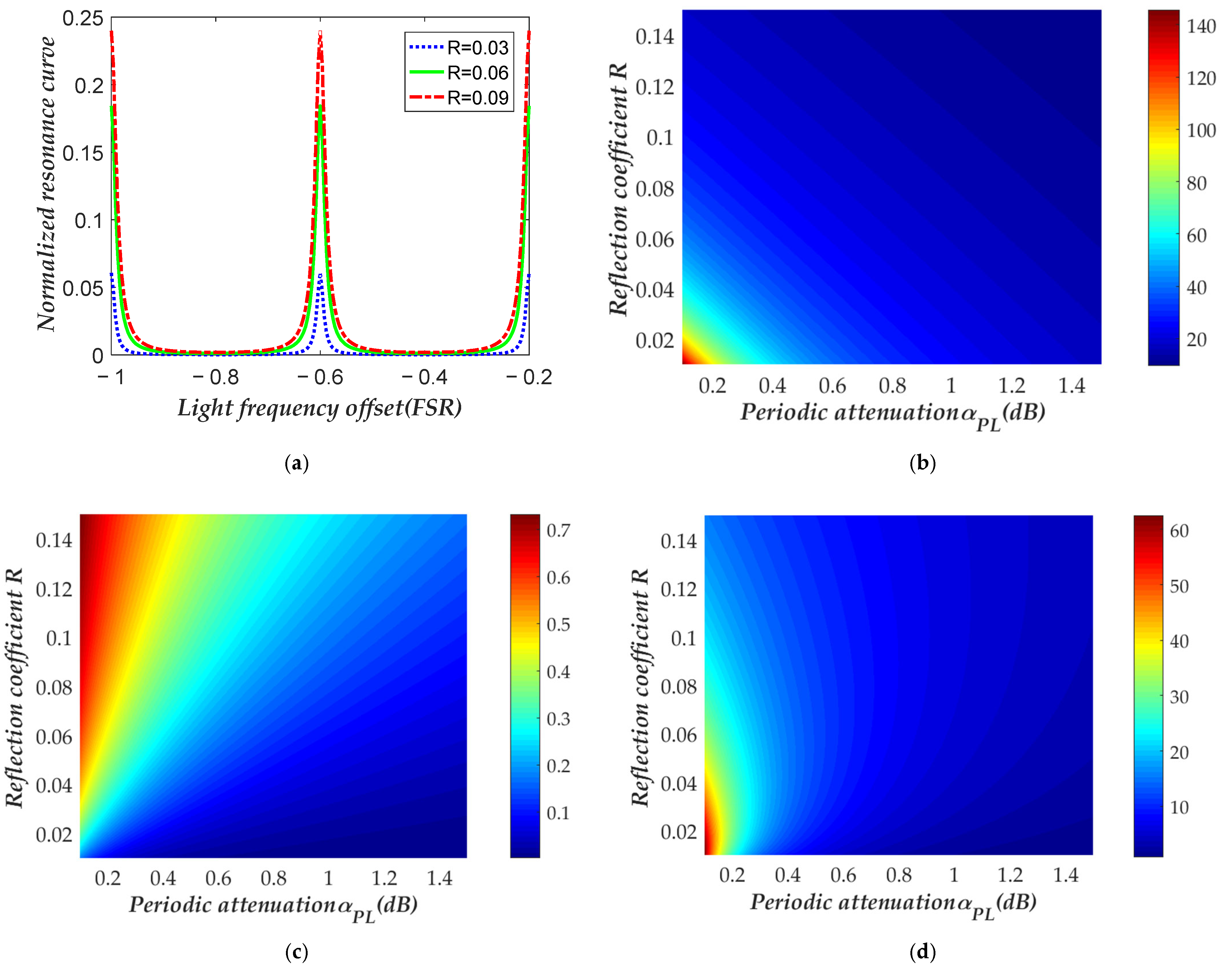
To achieve high sensitivity of the HC-RFOG, it is necessary to optimize the controllable parameters of the resonator. As shown in
Figure 2a, when
is a constant, the relationship between intensity of the resonance curve and R is simulated. As it tells that the smaller the value of
, the smaller the maximum intensity of the resonance curve.
Figure 2b shows the simulated results of the relationship between
and
when
takes different values. It can be observed that,
decreases as
increasing with under constant
.
Figure 2c shows the simulated relationship between
and
when
takes different values. As it shows that
increases as
increases with constant
.
is the primary parameter determining the final sensitivity of the RFOG [
16].
Figure 2d shows the simulated relationship between
and
when
takes different values. From the figure, it can be seen that when
takes different values, an appropriate
value can be selected to achieve the maximum value of
.
3. Mathematical Modeling and Simulation
The temperature-dependent bias drift of RFOGs arises from undesirable polarization eigenstates. When the phase difference between two co-propagating polarization eigenstates in the resonator reaches an integer multiple of during propagation, their optical powers become balanced, maximizing polarization-induced errors.
To eliminate such polarization errors, a resonator supporting only single-polarization eigenstate transmission becomes essential. This requirement stems from the fact that polarization-mode dispersion and birefringence effects in optical cavities critically influence error dynamics.
For a resonator with incident ports, the electric field intensities of clockwise (CW) and counterclockwise (CCW) propagating lights can be expressed as
Let
and
denote the angles between the polarization directions of CW and CCW propagating lights and the polarization axis of the fiber, respectively. Let
and
represent the phases of the CW and CCW lights. For computational simplicity, these phases are initialized to
,
. The transmission matrices for components within the resonator are defined as follows
Here,
is transmission matrix for CW light propagating between the polarizing beam splitter and the coupler port,
is transmission matrix for CCW light propagating between the PBS and the coupler port,
is transmission matrix for CW light between the PBS and the beam splitter.
is transmission matrix for CCW light between the PBS and the BS,
,
correspond to Jones matrices of PBS1 and PBS2, respectively, which mathematically describe their polarization-separating function discussed in
Section 2.
is transmission Jones matrix of the beam splitter,
is reflection Jones matrix of the BS.
is transmission matrix of the fiber ring,
is misalignment angle between the coupler port fiber and the PBS,
is Installation misalignment angle between the beam splitter and the PBS,
PER corresponds polarization extinction ratio of the PBS, respectively,
is average propagation constant of the HCPCF,
is birefringence-induced propagation constant difference in the HCPCF.
and
represent the refractive indices of the slow and fast axes of the HCPCF, respectively.
denotes the speed of light in vacuum
is phase difference between CW and CCW light induced by the angular velocity sensed by the resonator.
As previously discussed, the core of this resonator design is to achieve a high effective polarization extinction ratio
. This key parameter can be mathematically expressed as:
Among that,
denotes the normalized electric field intensity of light incident on the first PBS,
represents the normalized electric field intensity transmitted through the second PBS,
represents the common phase shared by
and
,
denotes the phase difference between
and
. The photocurrent
and
detected by photodetectors can be expressed as
Here,
,
denote the Jones matrices of the two beams incident on the resonator from Port1 and Port2, respectively,
and
represent the Jones matrices of the light propagating from the resonator to photodetectors,
,
correspond to the round-trip Jones matrices for CW and CCW propagation within the resonator,
,
describe the electric field equations of the two optical paths arriving at the photodetector, while
and
represent the photocurrent intensities of the two detected signals. The resonant frequencies
and
corresponding to CW and CCW paths of the resonator can be derived by
The bias error
of the gyro induced by polarization noise can be represented as
In Equation (8), denotes the optical wavelength, while denotes the diameter of the fiber loop.
As the phase difference ΔβΔL between the two co-propagating polarization eigenstates varies from 0 to 2π (where ΔL = Δn * L, L is the length of the HCPCF loop, Δn is the fiber’s birefringence and Δβ is the propagation constant difference induced by the Δn), their respective resonance curves drift relative to each other. This drift causes a shift in the servo system’s frequency locking point, which is incorrectly demodulated as a Sagnac frequency shift, thereby generating the gyro bias error Ωe.
It is important to clarify the assumptions made in this model. The model is not entirely idealized, as it explicitly incorporates the finite polarization extinction ratio of the polarizing beam splitters (PER_PBS) within their Jones matrices (Equations (11) and (12)). However, to maintain a tractable model, secondary effects such as cross-polarization and crosstalk in the beam splitters, as well as optical leakage between the coupler ports, have been omitted. While these non-ideal effects are considered minor, they likely contribute to the observed discrepancies between the simulation results and the experimental data.
,
and
are set to
. The PBS and the BSP within the coupler are fixed in grooves laser-etched into the silicon substrate. The range of
is
.
is set to
, and
is set to
.
Figure 3a shows a simulation of the relationship between
and
as
varies from
to
. As the absolute value of
decreases,
increases, and this variation exhibits periodic behavior depending on the value of
.
Figure 3b shows the simulation of the relationship between the minimum value of
and
. As
PER increases, the rate at which
decreases with the absolute value of
becomes faster.
Figure 4 presents the simulation of the relationship between
and
. The larger the
, the stronger the resonator’s ability to suppress polarization noise. When
is
reaches a certain value, the theoretical value of
is less than
. The 48 dB value cited in the abstract is derived from these simulations, representing the lower limit of the effective PER achievable under the specified simulation conditions, as illustrated in
Figure 3.
4. Experimental Results and Discussions
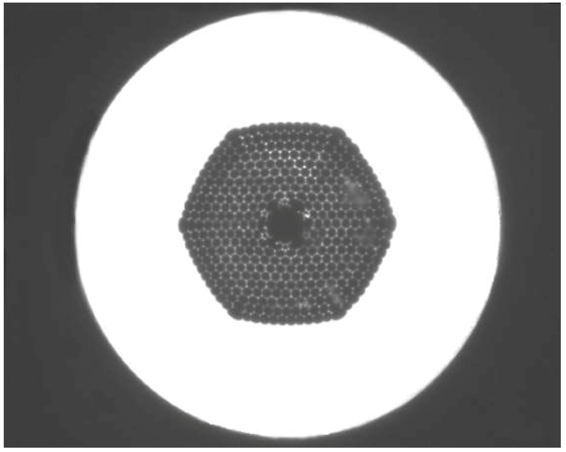
The sensing coil in our experiment was constructed using a commercial hollow-core photonic-crystal fiber (HC-PCF), model HC-1550-02 from NKT Photonics (as shown in
Figure 5). This fiber is designed for a central wavelength of 1550 nm, featuring a hollow core with a diameter of 10 ± 1 µm and a mode field diameter of 9 ± 1 µm. A critical characteristic for our application is its specified attenuation of 30 dB/km at 1550 nm. The fundamental advantage of this fiber is that over 95% of the optical power is confined within the air core, which drastically reduces material nonlinearities—a key factor in mitigating noise sources within the gyroscope.
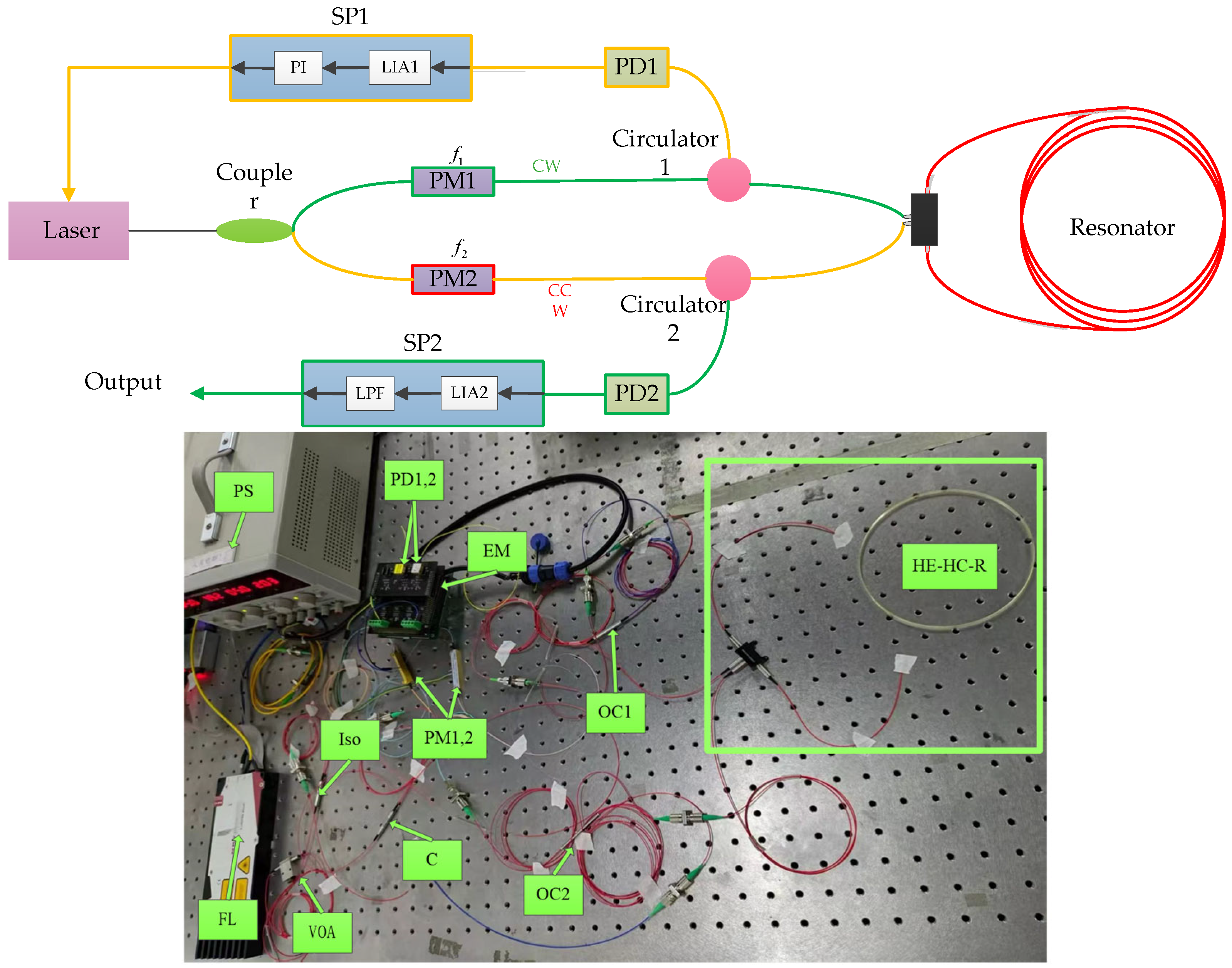
The system configuration of the HC-RFOG employing the HPERR is illustrated in
Figure 6. Light from a tunable narrow-linewidth laser is split by a coupler into two beams of equal optical power. These two beams are separately modulated by phase modulators PM1 and PM2 with different-frequency sine waves 45 KHz and 46 KHz. By adjusting the amplitude of these sine waves, bias drift arising from backscattering can be effectively suppressed. In addition, the phase modulator is also the core component of the closed-loop frequency-locking servo system. By modulating the phase of light and demodulating it with a lock-in amplifier, an error signal proportional to the deviation of the laser frequency from the resonance peak can be obtained. This signal is fed back to the PI controller, thereby precisely locking the laser frequency to the resonance peak, which is a necessary technology for achieving high-precision RFOG. Photodetectors PD1 and PD2 convert the CCW and CW optical signals emerging from the resonator into electrical signals, respectively. In the signal processing module SP1, the CCW signal is first routed through a lock-in amplifier LIA1 and then fed into a PI controller to stabilize the laser’s frequency. As a result, the laser is locked to the resonant frequency of the CCW optical path. In the signal processing module SP2, the CW signal passes through a lock-in amplifier LIA2 and a low-pass filter LPF. The digital output from SP2 is subsequently taken as the angular rate measured by the HC- RFOG.
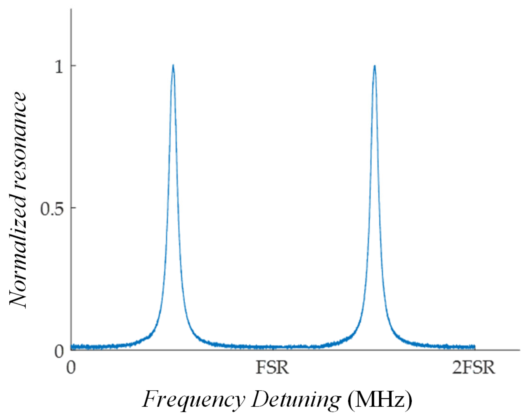
The HC-RFOG employing the HPERR scheme was tested. The measured resonator is shown in
Figure 7. This result is attributed to the HPERR architecture, in which the dual-PBS configuration acts as a high-fidelity cascaded filter, selecting and attenuating the undesired polarization state twice. Only a single polarization state was excited within the resonator. The periodic loss is 0.9 dB, R is 0.05, and F is 20. Meanwhile,
is 8.4% and
is 5.9. Furthermore, the Allan deviation is analyzed based on 1200 s gyros precision tests. As shown in
Figure 8a, the bias stability within 200 s of averaging is
, and the ARW was
. At the same time, the Allan deviation of the HC-RFOG without the HPERR scheme is also analyzed. As shown in
Figure 8b, its bias stability is
, and the ARW was
. Compared with the HC-RFOG without the HPERR scheme, the bias stability of the HC-RFOG employing the HPERR scheme improved by a factor of 13, and the ARW improved by a factor of 4.
Compared to earlier studies that also employed hollow-core photonic-crystal fiber (HC-PCF), the results presented in this paper represent a significant performance breakthrough. For example, Jiao et al. achieved a bias instability of 2.0°/h in 2017 using a transmissive single-beam splitter resonator, which was already a notable advancement at the time. Subsequently, in 2018, they further improved long-term bias stability to 20°/h by adopting a single-polarization resonator based on a micro-optic polarization coupler. In contrast, this study introduces an innovative high-polarization-extinction-ratio resonator (HPERR) architecture, achieving a bias instability of 1.34°/h—approximately 20 times better than the aforementioned study, respectively. This comparison clearly demonstrates that even when using conventional HC-PCF of the same type, the proposed HPERR architecture exhibits exceptional capability in suppressing polarization noise, serving as the key factor enabling an order-of-magnitude leap in performance. Consequently, the precision of HC-RFOG has been elevated from industrial or basic tactical grade to the threshold of high-end tactical grade and even navigation grade.
5. Conclusions
In this study, we primarily focus on verifying the principle effectiveness of the High-Polarization-Extinction-Ratio Resonator (HPERR) in suppressing polarization noise, so the experiments were conducted in a relatively stable laboratory environment. We believe that this solution has inherent advantages in terms of environmental adaptability. First, the hollow-core photonic-crystal fiber (HC-PCF) used in the research inherently exhibits significantly lower temperature sensitivity and nonlinear effects compared to traditional polarization-maintaining fibers. This fundamentally reduces errors caused by temperature fluctuations. Second, the core design of our HPERR aims to achieve an extremely high polarization extinction ratio, making the resonator less sensitive to residual birefringence fluctuations induced by stress, vibration, or temperature changes, thereby maintaining a more stable single-polarization operation. Nevertheless, comprehensive environmental adaptability tests—including temperature cycling tests over a wide temperature range and performance evaluations under various vibration conditions—are crucial for validating the tactical-grade application potential of this gyroscope. This aspect will be the focus of our next phase of research, during which we will develop a more robust and compact integrated prototype and conduct systematic environmental stability tests.
In conclusion, we have successfully designed and demonstrated a high-polarization-extinction-ratio resonator (HPERR) that effectively suppresses polarization-induced noise in HC-RFOGs by ensuring high-fidelity, single-polarization-state operation. The prototype gyroscope achieved a bias instability of and an angle random walk of over a 200 s averaging time, performance metrics that validate the design’s suitability for tactical-grade applications. While these results are significant, a performance gap remains between the experimental data and the theoretical limit. Our analysis indicates that this discrepancy is primarily caused by residual backscattering noise, which was not completely suppressed. Therefore, mitigating backscattering-induced errors represents the next critical step in our research and is essential for unlocking the full potential of this high-performance HC-RFOG architecture.
