1. Introduction
Free-space optical (FSO) communication technology provides higher bandwidth and data rate than other wireless communication techniques such as radio frequency communication [
1]. In the near future, lasers are expected to be widely used in communication systems. Space communications and radar systems will use free-propagating laser beams as signal carriers, and the application demand for communication between multiple mobile platforms [
2] will also increase accordingly.
Point-to-multipoint communication can effectively utilize limited spectrum resources, with lower costs and higher scalability and network flexibility [
3]. However, free-space optics (FSO) is considered primarily for establishing point-to-point (PtP) connections. Due to the increasing demand for mobile platforms and mechanisms to establish point-to-multipoint (PtM) connections, many solutions have been proposed to improve the current FSO system, such as a new PtM tracking mechanism [
4] to ensure fast link alignment, the application of the Fast ICA algorithm [
5] to adapt to atmospheric conditions under different turbulence, and the introduction of stepping motors to control the array of reflectors [
6].
In addition, some scholars have proposed and experimentally demonstrated PtM systems based on liquid crystal optical phased arrays [
7] or liquid crystal variable retarder cascaded polarization gratings [
8], but the response times of liquid crystal phased arrays are typically in the ms range [
8,
9,
10,
11,
12], which may not meet the requirements of fast acquisition, tracking, and pointing (ATP) when applied on mobile platforms.
In the above context, the silicon-based OPA (optical phased array) has attracted the attention of researchers due to its advantages such as high-speed light field manipulation characteristics. In recent years, many scholars have conducted in-depth research on the application of its beam-steering capabilities in the field of communications [
13]. The potential of silicon-based OPA for PtM has been theoretically analyzed, simulated, and experimentally verified [
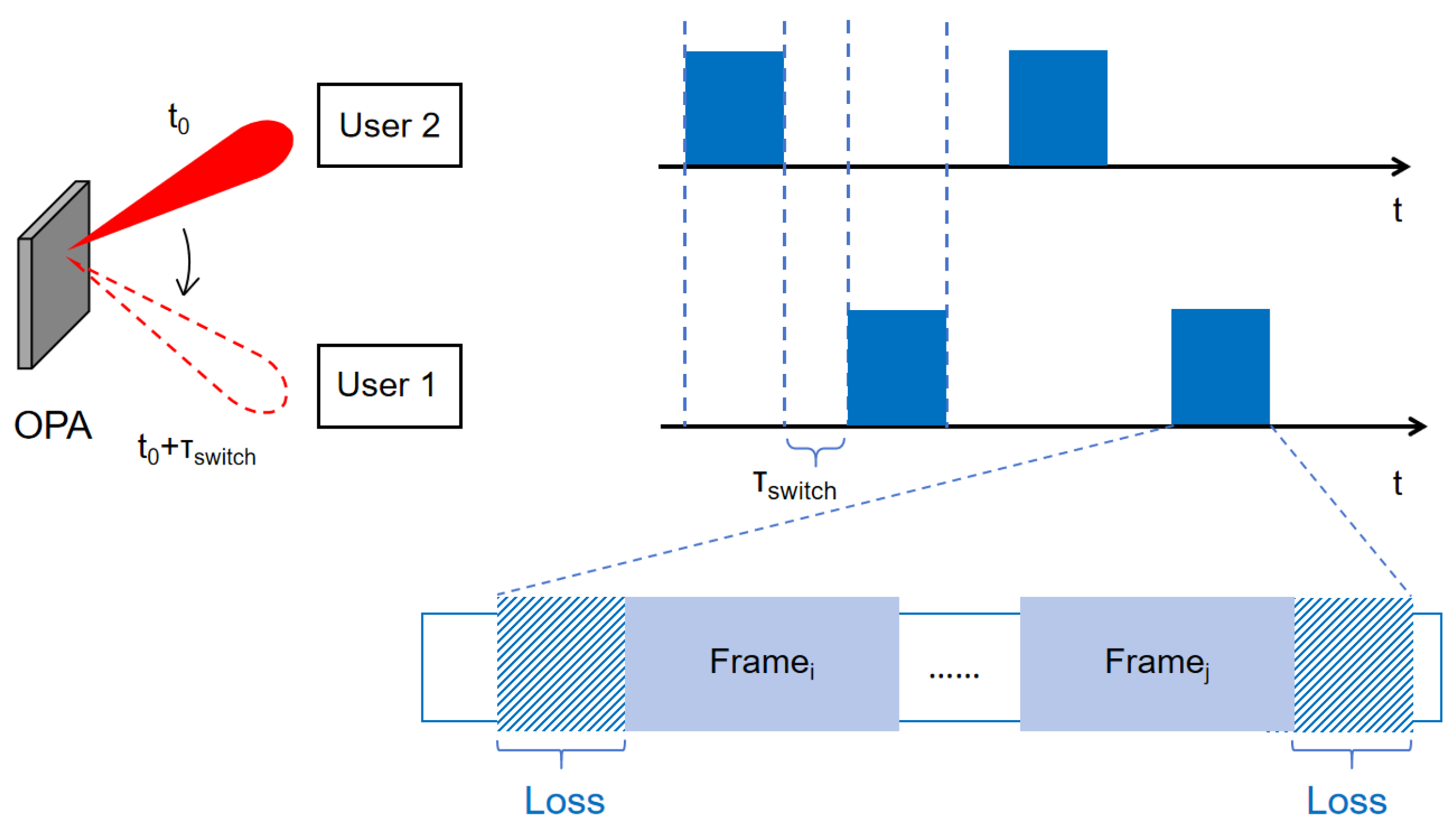
14]. Previous studies combined the two research fields of optical phased array and laser communication theory, utilized the scanning characteristics of the optical phased array, and realized the time division multiplexing of the channel. However, the drawbacks of this approach are difficult to avoid. For example, in the scenario of single-beam scanning with multi-target reception, the beam switch requires a control time of about tens of microseconds. During this process, data cannot be effectively transmitted, resulting in a certain amount of resource waste, as shown in
switch1 in
Figure 1. In addition, each time the receiver is switched, frame synchronization needs to be re-performed, resulting in the invalidation of the data before the frame header, as shown in
Figure 1. As the scanning frequency increases, more switches occur per second, and the proportion of waste caused by the aforementioned situation also increases.For communications with moving objects as mentioned in [
14], this effect causes even greater waste, because after each switch, tracking and link establishment must be re-performed to obtain alignment.
To address the above issues, we fully utilized the optical field control capability of silicon-based OPA and used the aperture division method to generate a beam with multiple main lobes. With multiple access technology to achieve unbroken PtM links, we conducted detailed data analysis. Experimental verification showed that compared with the beam-switching solution, this scheme can avoid the loss of up to 24.576%, and the communication efficiency is significantly improved.
2. Materials and Methods
OPA is a phase-adjustable optical antenna array, and its working principle is similar to that of a microwave phased array. A beam of light is divided into multiple optical signals through an optical beam splitter; after the phase difference is added to each optical signal, the equal phase plane is no longer perpendicular to the waveguide direction, but has a certain deflection. The beams that meet the equal phase relationship will coherently constructive, and the beams that do not meet the equal phase condition will cancel each other out, so the direction of the beam is always perpendicular to the equal phase plane. Therefore, the introduction of phase difference in the array element completes the beam deflection effect, without the need for a mechanical servo system, and beam steering is achieved by controlling the phase of the light radiated by each optical antenna.
Sub-aperture means that different areas of the optical phased array are calibrated at different angles to generate multiple light beams that point to different receivers. In order to form two light beams at the output end, the total aperture of the silicon-based OPA is divided into two different logical sub-apertures, and each sub-aperture is regarded as a small OPA that can be controlled individually [
15]. The electrical control system applies different voltages to the waveguide units in the phase-shifting areas corresponding to the two sub-apertures, so that the light beams passing through each phase-shifting area are subjected to different phase modulations, thereby satisfying the phase difference corresponding to each angle. At this time, the light beam at the output end will point in two directions, thus forming a double light beam.
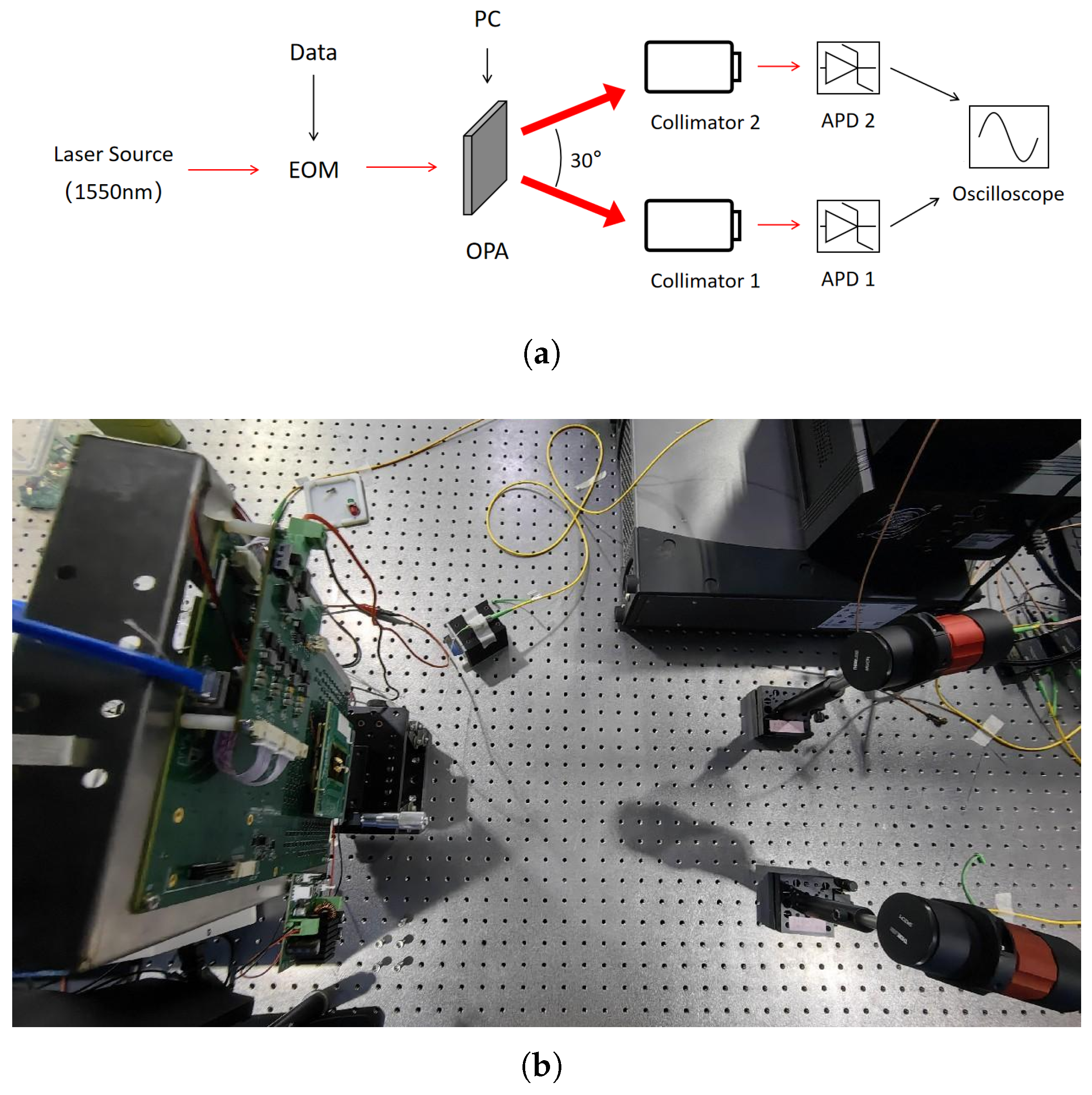
The experimental setup is shown in
Figure 2. The 1 Gbps signal is generated from an Arbitrary Waveform Generator (AWG, KEYSIGHT M8195A) and emitted using an optical phased array after electro-optical intensity modulation (by CONQUER KG-AMBOX-15-10G-PS-FA). The azimuth control of the optical phased array output light is realized by computer software. The experiment uses a 512-channel silicon integrated optical phased array, which divides these channels into the first 256 and the last 256 channels in sequence to generate beams respectively, so that they point to the directions of −15° and +15°. Since the power of the OPA’s sidelobes drops considerably at larger angles like 30°, it presents an ideal scenario for testing. The fact that both independent receivers achieve a comparable and low BER at this angle provides strong evidence that each is being addressed by a dedicated main lobe, rather than one being served by a sidelobe.
The optical phased array calibration program used is based on the hill climbing algorithm, the spgd algorithm, and other commonly used calibration algorithms. The algorithm is improved to obtain a sidelobe suppression ratio of the beam greater than 10 dB. Compared with one single beam, this method causes a certain spot broadening and power reduction, but it results in a low level of grating lobes. After the light emitted by the OPA is transmitted through a free space of about 47 cm, the two signals are received by two collimators (THORLABS C80APC-C) respectively, and finally visualized on an oscilloscope (KEYSIGHT UXR0104A) through an avalanche photodetector (APD, KEYANG PHOTONICS KY-APRM-1.5G-I-FA).
The beam-steering principle of an OPA dictates that the emission angle is inherently coupled to the wavelength of the light, and devices utilizing this principle for 2D beam scanning have also been reported in the literature [
16,
17]. Therefore, to ensure a stable and directive communication link, our current system is designed and optimized for a single wavelength (1550 nm).
Assume that the receiver in the +15° direction is user 1, and the receiver in the −15° direction is user 2. Because this study uses intensity modulation, code division multiple access (CDMA) is very suitable for realizing multi-user communication; that is, different receivers use different secret keys for decoding. Each of the two receivers is assigned a unique 4-bit chip sequence. While longer codes would offer better performance, they impose a system trade-off: either they sacrifice data rate for the same bandwidth or increase the system bandwidth to maintain the original data rate. According to the generation principle of Walsh codes, a 4-bit length can theoretically support up to four users, which is inadequate for practical applications. Since this work is a lab-scale demonstration focused on validating the OPA’s multi-beam emission and simultaneous communication capability, a shorter code was deemed sufficient.
Figure 3 briefly shows the CDMA simulation process of the original data for spread spectrum transmission.
We collect data on the oscilloscope and restore the data for the post-processing. The processing chain, including matched filtering, threshold judgment, and correlation despreading, was implemented in MATLAB R2025a. The code is available in the uploaded
Supplementary Materials. The xcorr() function is used for preamble correlation and frame synchronization, followed by a threshold decision for symbol slicing. Finally, despreading is performed via matrix multiplication with the Walsh code matrix. Also, bit error rate analysis is performed. Because the Barker code has a sharp autocorrelation function, the experiment uses a 13-bit Barker code as the frame header.
3. Results
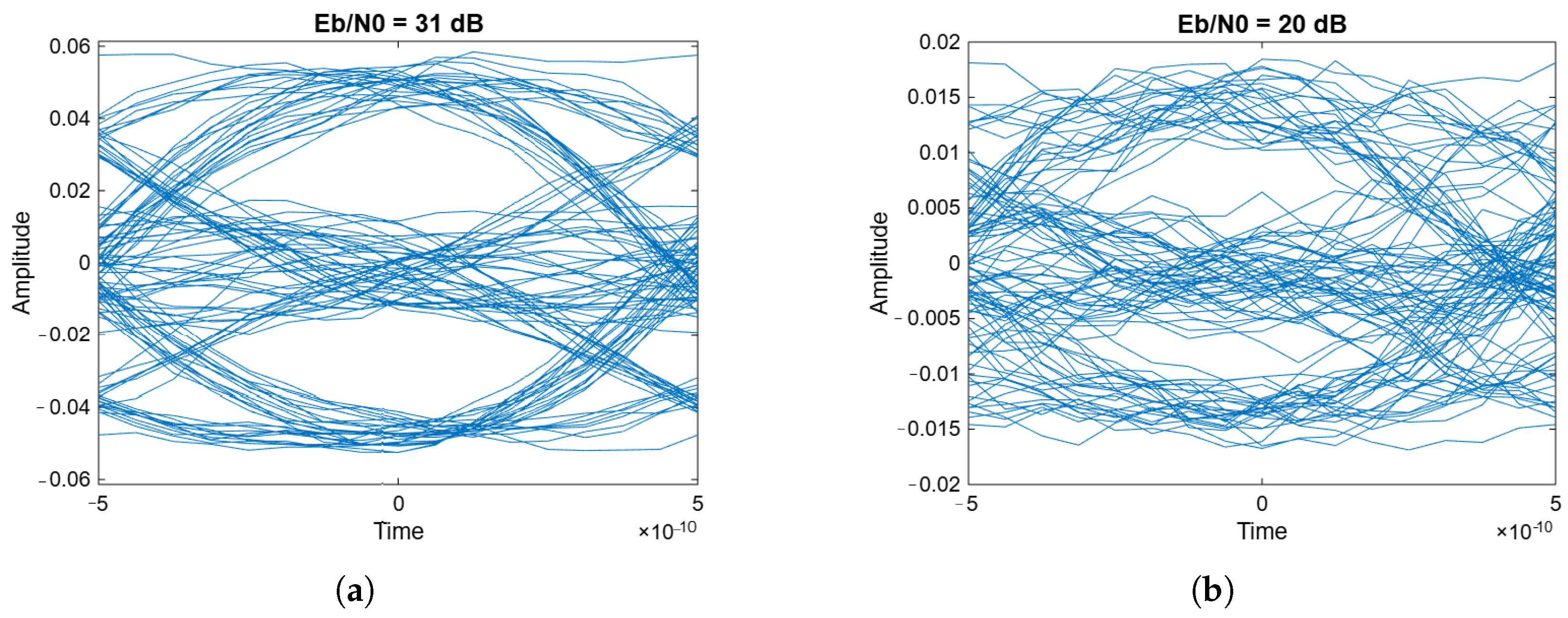
Two eye diagrams of the received signal obtained from the experiment are shown in
Figure 4.
In order to conduct quantitative analysis, the bit signal-to-noise ratio Eb/N0 is required. Eb/N0 refers to the ratio of the energy required for a communication system to transmit one bit of information to the noise power spectrum density. It can eliminate the influence of spectrum efficiency under different modulation technologies and is an important indicator for normalizing the performance of the entire communication system. Since it is difficult to actually measure Eb/N0, while it is easier to measure the signal-to-noise ratio (SNR), a conversion relationship between Eb/N0 and SNR is needed.
In a CDMA system, the conversion relationship between Eb/N0 and SNR is [
18]
The logarithmic form of this formula is
in which Eb represents the energy per bit (Joules), N0 represents the power spectral density of noise (Watts/Hz), S represents signal power (Watts), and N represents noise power (Watts).
is the channel coding rate of the communication system, which was not used in this study, so
. Rm is the modulation rate of the communication system, and
, where M is the number of modulation constellation points. For OOK, M = 2. D is the spreading factor, and in this study, n = 4 chips were used, so d = 4.
is the roll-off factor of the root-raised-cosine filter, and
. The frame structure efficiency
is used to characterize the overhead of the pilot sequence used for synchronization in the system frame structure. In this system, a 13 bit Barker code is used as the frame header, and one frame contains 200 symbols, so
.
SNR can be obtained by calculating the power of the received signal and the power of the device background noise. In this study, the root mean square (RMS) is used as a characterization, where the device noise floor is measured under the conditions of shielding the OPA antenna, powering the APD, and receiving the same background light.
The data measured in the experiment are shown in
Table 1. For scenarios involving extremely low bit error rates (beyond the equipment’s measurement threshold), 95% BER confidence interval estimation based on the Poisson distribution has been incorporated to replace zero values.
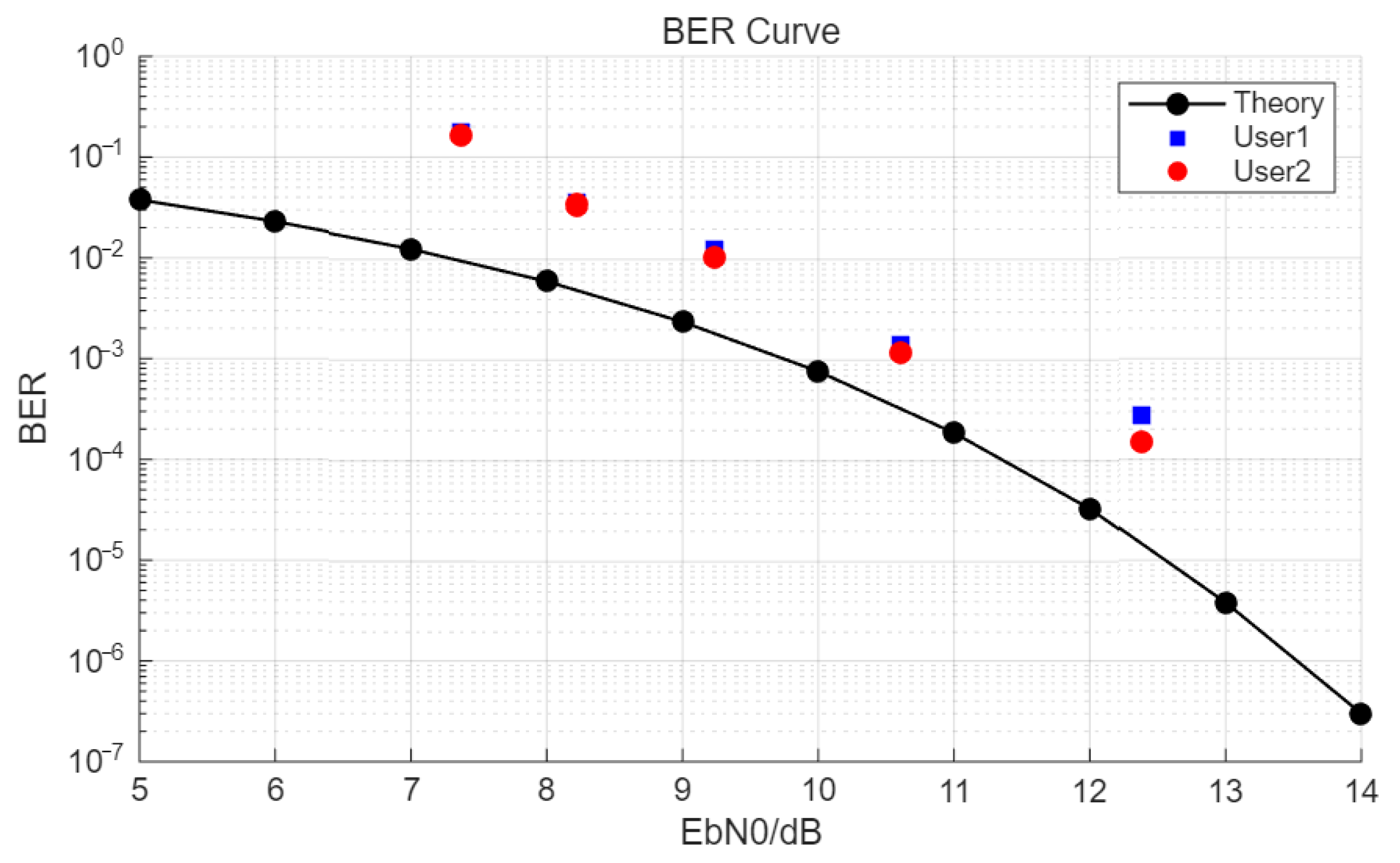
Figure 5 shows a comparison of the experimental results and the theoretical bit error rate curve of OOK modulation.
By comparison, it is found that under the same bit error rate result, the actual system is usually worse than the theoretical one. It is considered that this loss is the error introduced by the signal itself, such as the rising and falling edge time of the APD response, uneven modulation, or OPA light intensity flickering. For the two receiving ends, the loss is basically uniform.
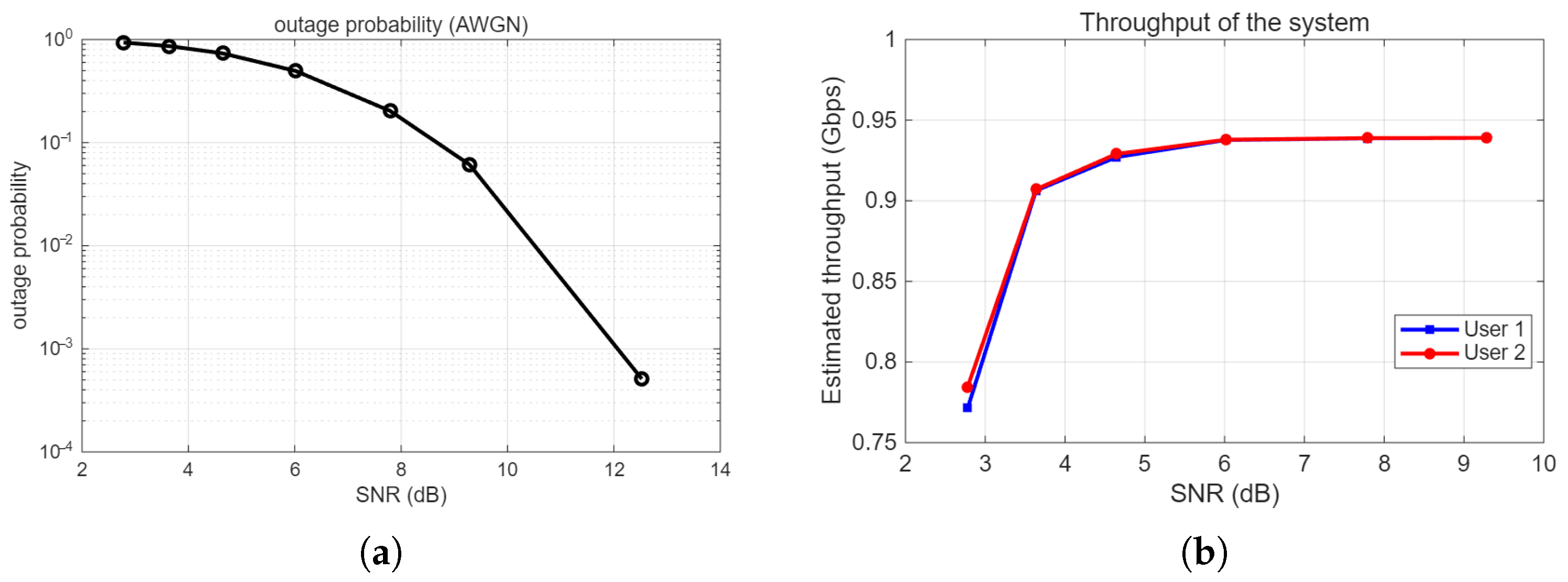
The outage probability and throughput of the experimental system are also preliminarily analyzed and estimated, as shown in
Figure 6.
An outage is considered to occur when the instantaneous SNR falls below the common Forward Error Correction (FEC) threshold (BER < 1× 10
−3, corresponding to an SNR of approximately 3.99 namely 6.0 dB, in
Table 1). Given the short-range, unobstructed, and stable conditions of our laboratory environment, the channel is modeled as an Additive White Gaussian Noise (AWGN) channel. Based on this model and the signal data measured at different received power levels, we have derived the corresponding outage probabilities through theoretical calculation, as shown in
Figure 6a. The throughput of the laboratory environment is determined by
where the physical layer data rate R is 1 Gbps, and frame efficiency
. In a laboratory proof-of-concept environment, when channel conditions are favorable, the measured BER is extremely low, and its impact on throughput is negligible. Therefore, under these specific test conditions, the effective throughput is approximately 0.939 Gbps. When the SNR is low, we use the BER to estimate the channel throughput, as shown in
Figure 6b.
A comprehensive investigation of the outage probability and throughput under more diverse and practical channel conditions (such as scenarios involving obstructions or dynamic changes) constitutes an important part of our future research plan.
In addition, the same set of equipment was used to compare the receiving power and energy efficiency of the time-sharing scheme and the aperture-dividing scheme under the same conditions. The receiving power comparison is shown in
Table 2. Among them, the light source output power is 20 mW, and after the electro-optical intensity modulation, the output is 3.6 mW, which is transmitted to the OPA. The output of the light source, the modulator, and the spatial light transmission distance are basically unchanged, but by comparing the table, it can be found that the power of the aperture-dividing scheme is significantly reduced compared to the time-sharing scheme, and it is smaller starting from the OPA light output. It is speculated that the split use of the aperture leads to lower transmission power under the same conditions. This brings certain challenges to alignment and spatial optical coupling in practical applications, and reduces the signal-to-noise ratio of the system.
Ideally, the energy efficiency of the time-sharing and aperture-dividing schemes should be the same, with each user receiving half of the total transmitted power.
However, beam switching is not instantaneous. For each user, the percentage of switching time in the ideal cycle is
where
indicates that the beam switches and points to this terminal, and
indicates that the beam leaves, as shown in
Figure 1. The beam-switching time of OPA used in the research is
s,
s. For the employed switching frequency of 10 K times per second (i.e.,
s) and the measured switching time,
. For higher switching frequencies, this value will be larger when the OPA performance remains unchanged.
Additionally, non-ideal synchronization states may also introduce losses. This is because before the beam is fully aligned and reaches the maximum receiving power, the data received by the receiving end is likely to be invalid. In the best case, by introducing other synchronization mechanisms, the transmitter starts sending a frame immediately after the beam is fully aligned. The worst case is that the beam is just aligned after the transmitter sends a frame. The same is true when the beam leaves the receiving end. Therefore, additional losses are generated:
where k is a parameter related to system synchronization capability, ranging from 0 to 1. The signal used has
s, which leads to additional loss of 0.426% at most compared to the ideal situation.
For the time division scheme, we have
These two kinds of losses do not exist in the multi-user simultaneous communication scheme, because each receiver has its fixed main lobe to communicate. Therefore, the experiment proves that the aperture-dividing scheme significantly improves the communication efficiency in some cases.
4. Discussion
In combination with the sub-aperture method and code division multiple access, we demonstrated the feasibility of multi-user simultaneous online spatial optical communication technology based on an optical phased array and the construction of an experimental system was completed.
In this work, we have conducted quantitative analysis of the OPA-based multi-user system’s performance boundaries under challenging low-SNR conditions. While recent OPA studies often rely on higher transmission power [
13,
19] to achieve robust performance, they seldom explore performance boundaries under low-SNR conditions. In contrast, our work systematically quantifies the OPA-based system’s tolerance in noisy channels by measuring achievable BER across varying SNR levels. Furthermore, we estimate key practical metrics such as system outage probability and throughput, providing valuable references for system designers to determine practical operational limits.
Time division (TD) beam-steering remains a widely adopted approach for multi-user links in recent OPA-enabled communication studies [
14,
20]. Yet, the comparative efficiency of TD against simultaneous multi-beam schemes has rarely been quantified. Here, we present the first experimental side-by-side evaluation between our simultaneous multi-aperture CDMA architecture and a TD alternative, under fixed total power constraints. The results clearly show that our approach achieves higher aggregate communication efficiency, offering a feasible and power-effective reference for future OPA-based free-space optical systems.
At the current technological level, optical phased arrays still have certain limitations that restrict the scalability of the proposed system in long-distance or mobile optical links. Large-scale OPAs with high performance typically require considerable power budgets [
21]. Given that the power of our OPA driver board is approximately 30 W, its power consumption will be a critical challenge to overcome for applications in long-distance or mobile FSO links. Beyond power concerns, typical beam divergence is given in units of degrees, along both the scan axis and the orthogonal axis, which may restrict long-range applications [
19,
22]. The divergence angles of the employed OPA were measured to be 0.086° and 0.023° in the X and Y directions respectively, which may reduce the power density at the receiver and increase the difficulty of alignment, thus restricting long-range or mobile-link applications. The stringent requirement for both spot and optical axis alignment in free-space optical communications makes a sidelobe suppression ratio exceeding 10 dB potentially insufficient to completely eliminate crosstalk in long-distance and mobile links. This form of interference can be largely eradicated by further increasing the sidelobe suppression ratio or incorporating measures such as identity codes. Additionally, thermal and electrical drifts commonly occur in driving circuits, and OPAs are highly sensitive to phase mismatches among array elements, making ongoing calibration essential [
23,
24]. Considering the consistency of our experimental data and the observed degradation, we adopt a recalibration interval of two months to maintain optimal beam pointing accuracy.
In conclusion, while the current system remains at the experimental validation stage, its architectural design is well aligned with the evolving roadmap of both OPA and free-space optical (FSO) communication technologies. In the near future, improvements in optoelectronic integration (for power savings), OPA aperture optimization (to reduce beam divergence), and the application of adaptive algorithms (to compensate for atmospheric and mobile links) represent necessary pathways toward realizing long-range or mobile FSO links. This kind of technology has broad application prospects in the communication field, which is conducive to reducing the cost of communication terminals used in space optical communications and improving network flexibility. As a candidate device for inter-satellite communication, OPA will completely change the data communication and telecommunications industries through tightly integrated high-speed modules.
