1. Introduction
Laser detection technology, noted for its long-distance measurement capabilities, high spatial resolution, independence from ambient lighting conditions, and adaptability to complex and dynamic environments, has undergone rapid development in recent years. Currently, LiDAR technology is extensively applied in numerous fields including autonomous driving [
1], atmospheric monitoring [
2,
3], marine phytoplankton detection [
4], fog warning systems [
5], vital signs monitoring [
6], 3D imaging [
7], and more.
Among the diverse LiDAR technologies, time of flight (ToF) LiDAR stands out for its extensive application [
8,
9,
10]. This technology operates by emitting a short laser pulse, recording the time elapsed from emission to reflection, and then converting this time interval into distance measurements to determine the location of the target object. Its widespread use is attributed to its relatively simple architecture and design. Moreover, ToF LiDAR is notably robust against external environmental disturbances.
LiDAR systems are classified into two types: non-coaxial and coaxial, based on whether their transmitting and receiving paths overlap. In non-coaxial LiDAR, the fields of view of the emitter and receiver are aligned along separate axes [
11,
12], leading to incomplete overlap, particularly in the near field. This effect is especially pronounced when using scanning methods such as galvos or polygon scanners, where the degree of non-overlap can further influence near-field measurements in LiDAR [
13,
14].
Another method is to use the design of coaxial LiDAR, where the transmitted and received light of coaxial LiDAR are along the same axis [
15,
16]. The complete overlap of the field of view helps to reduce signal loss and provide more stable and reliable signals in long-distance and complex environments.
To effectively implement coaxial LiDAR, the system’s structure can be designed as either a free-space optical system or a fiber-optic system. Free-space optical systems employ various components such as beam splitters [
17,
18], mirrors placed in front of the receiving lens [
19], omni-directional lenses [
20], or parabolic mirrors with central holes to achieve a coaxial transceiver functionality [
21]. However, these systems are inherently complex and more vulnerable to external environmental disturbances, thus demanding a higher precision in the alignment and stability of the optical path.
Given the typically demanding application environments for LiDAR [
22,
23], it becomes important to use a fiber-optic system as the primary structure, owing to its greater stability. Fiber-optic systems offer numerous advantages such as the ability to separate the optical system from the photodetector, simpler maintenance, easier integration, a compact optical path, lower manufacturing costs, reduced size, and enhanced safety.
The traditional fiber-optic coaxial LiDAR typically employs a fiber-optic circulator to separate the transmitter and receiver and guide the reflected echo signal to the photodetector. However, this approach presents notable limitations. According to wave optics principles, effectively capturing light that is back-reflected from the target object into the optical fiber end face is challenging [
24]. Additionally, to maintain high lateral resolution throughout the detection range, a lens with a low numerical aperture (NA) is commonly used to produce a collimated emitting beam. However, such a design leads to compromised collection efficiency of the echo beam, reflected or scattered by the target, due to the small aperture of the single-mode fiber (SMF).
In this paper, we propose a receiver utilizing a double-clad fiber (DCF) coupler to develop a coaxial LiDAR system. This design enhances performance in two critical aspects: laser emission and echo signal reception. Compared to traditional methods, our LiDAR system features a large receiving aperture, with the capability to emit lasers with a small output spot, allowing for improvement in lateral resolution.
2. Principle and Experimental Setup
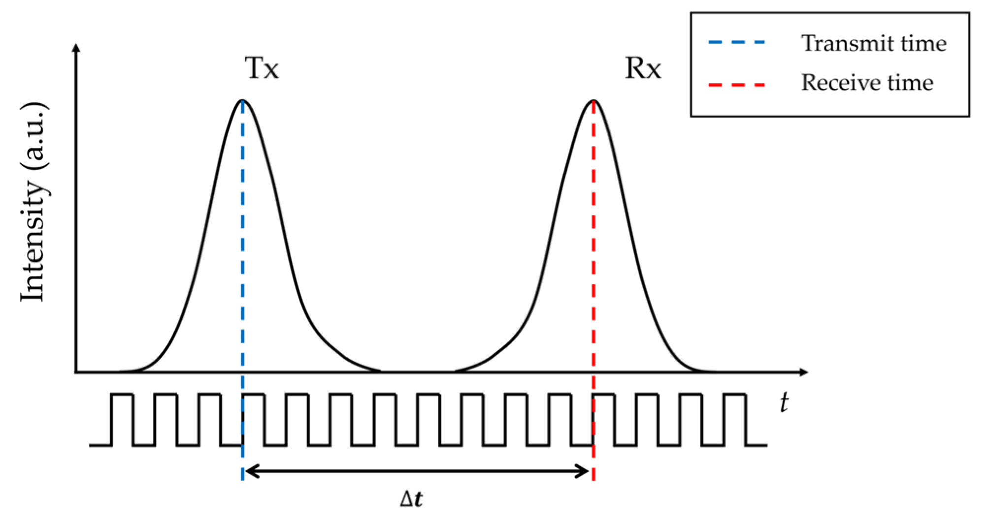
Figure 1 illustrates the principle of LiDAR ranging based on direct ToF (dToF) [
25]. The laser emits periodic pulses (Tx) while simultaneously generating synchronous signals that are used to trigger the data acquisition system (DAQ) to start both data collection and timing. Upon receiving the laser echo signal (Rx), the photodetector (PD) converts it into an electrical signal, which is then transmitted to the DAQ. The duration
, representing the time difference recorded by the timer, indicates the time taken for light to travel from the source, reflect off the object, and return. Finally, the distance to the target, R, is determined as:
where
is the speed of light.
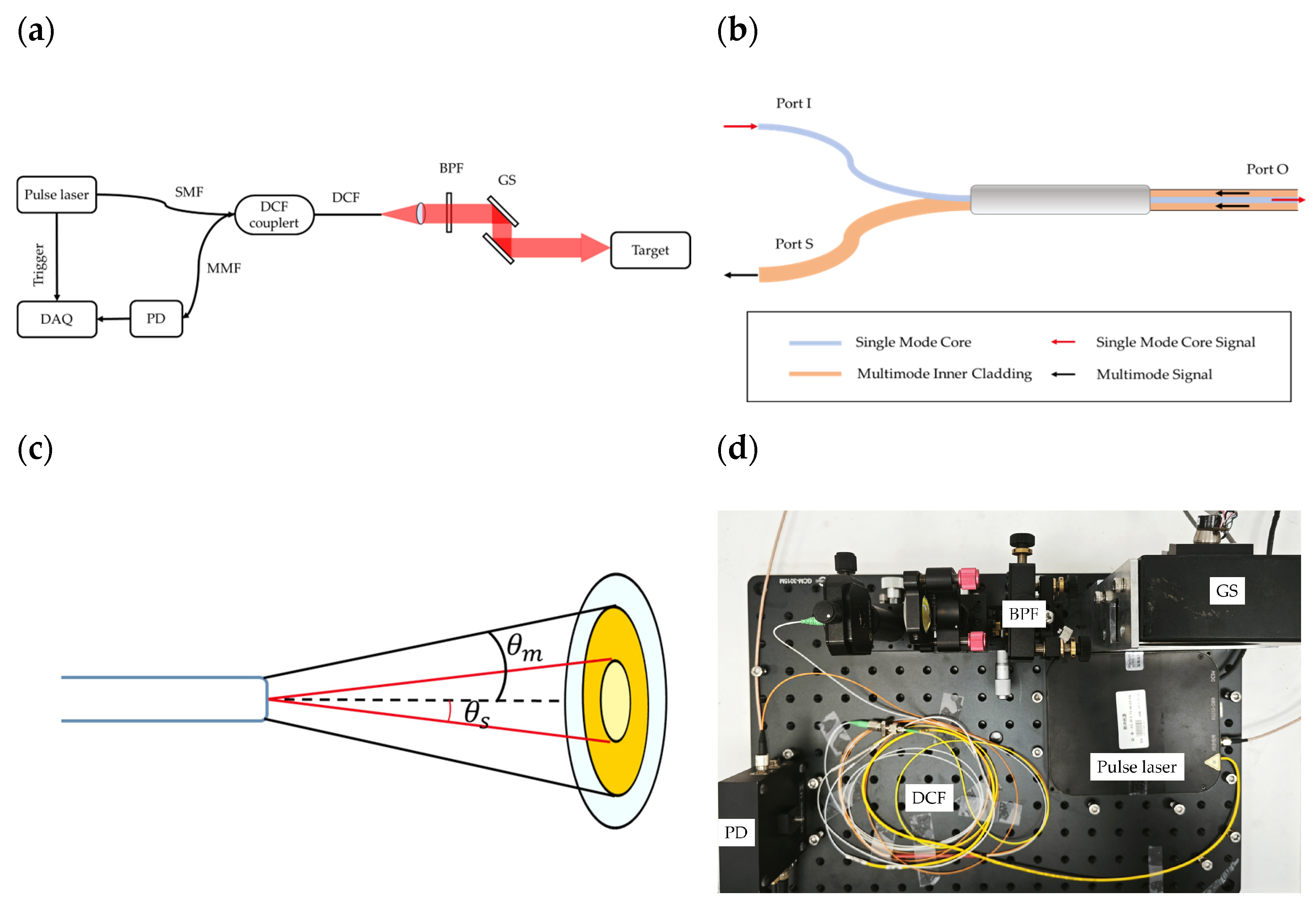
Figure 2a shows the architecture of the proposed ToF LiDAR system based on a DCF receiver. The system employs a pulse laser (Conquer, Bei Jing, China, KG-PLS-15-M-03-FA) with a central wavelength of 1550 nm, pulse width of 30 ns, repetition rate of 100 kHz, and peak output power of 5 W as the light source. In
Figure 2b,c the red line represents the single-mode light beam, and the black line indicates the multimode light beam. Port I connects to the laser, Port S to the photodetector, and Port O is utilized for both emission and collection of light. The laser is coupled into a DCF coupler (Thorlabs, Newton, New Jersey, United States, DC1300LEFA) and then emitted through the single-mode core of the output DCF of the coupler, with a diameter of 9 μm and a NA of 0.12. The emitted single-mode light is collimated and then scanned onto the target through a galvanometer scanner. The light beam reflected from the target is collected on its return path by the multimode inner cladding (diameter 105 μm, NA 0.22) of the DCF, coupled into a multimode output fiber by the DCF coupler, and then detected by a photodetector (Thorlabs, PDB450C). The detected signal is recorded by a DAQ (National Instruments, Austin, Texas, United States, PCI-5122), which features dual-channel 14-bit resolution, a sampling rate of 100 MS/s, and a bandwidth of 100 MHz. To synchronize the start time of acquisition with the laser pulse emission, the synchronous trigger signal from the laser is used as the trigger for the DAQ.
The collected echo power can be expressed as [
19]:
In this equation, represents the transmission power, denotes the atmospheric transmission efficiency, indicates the target reflectivity, is the equivalent area of the optical receiver, refers to the spot size when the laser illuminates the target, is the size of the target illuminated by the laser, and is the distance to the target object. According to this equation, firstly, to minimize the loss of echo signal strength and crosstalk between signals, it is advantageous to decrease the spot size so that , thereby ensuring maximum possible irradiation on the same surface. Secondly, enhancing the signal-to-noise ratio of the received signal requires maximizing the equivalent area of the optical receiver, .
In a non-coaxial LiDAR configuration, the illuminated spot and the receiver’s optical axis are not collinear. As a result, the return beam is intercepted off-axis at the receiver [
26], producing a near-range blind zone. As indicated by (2), since the received power at the detector scales with the receiver aperture, achieving sufficient signal power at long ranges generally precludes the use of small, short-focal-length collection optics. Balancing these considerations, this work employs a collection lens with a 25.4 mm diameter and 30 mm focal length. Under this configuration, the beam waist is 3.6 mm, and the return spot is displaced by 12.7 mm from the receiver optical axis. The resulting off-axis displacement of the return beam as a function of range is summarized in
Table 1.
A typical photodetector has an active-area radius of approximately 150 μm. As summarized in
Table 1, this geometry implies a near-field blind zone of ≈2.5 m to enable return collection at 100 m. Consequently, adopting a coaxial receiving configuration becomes necessary.
The spot radius,
, of the laser output from the optical fiber can be calculated based on the Gaussian beam principle as follows:
where
represents the beam waist radius,
is the propagation distance, and
denotes the laser’s central wavelength. When the laser from the fiber is collimated and exits through a lens with a focal length of 30 mm, the beam waist radius,
is 3.6 mm. Following a transmission distance of 50 m, the spot radius reaches 7.7 mm, and the horizontal angular resolution attains 0.018°, satisfying the resolution requirements for LiDAR systems.
In coaxial LiDAR, receiver architectures can be broadly categorized into free-space and fiber-based implementations. Free-space designs offer a larger effective collection area, and the photosensitive area of the photodiode is typically much larger than a fiber end face. However, free-space coaxial systems often require more intricate optical assemblies, which increases design complexity and alignment overhead [
17,
18,
19,
20,
21]. In practice, the two categories tend to serve different application niches: free-space configurations are favored when large apertures, high optical power handling, or direct sensor coupling are required, whereas fiber-based configurations are preferred for compactness, robust alignment over time, ease of routing, and modular integration with fiber components.
This work focuses on the advantages and limitations of several fiber-based coaxial configurations. For clarity, the port interfacing the light source is denoted Port I, the laser output port is Port O, and the port connected to the photodetector is Port S (consistent with
Figure 2b). A multimode fiber (MMF) circulator (e.g., Thorlabs, WMC3L1S) offers a large receiving area (core diameter ≈ 200 μm) and low insertion loss (<0.8 dB). However, its large numerical aperture (NA = 0.22) enlarges the emitted beam radius (>7 mm), and, correspondingly, the spot size at the receiver increases upon return. This results in substantial signal loss and a weaker received echo. In addition, MMF circulators exhibit crosstalk from Port I to Port S, which may contaminate the return path. By contrast, an SMF coupler provides the lowest transmission loss (<0.6 dB). Nevertheless, as summarized in
Table 1, the SMF receiving area (core diameter ≈ 9 μm) often cannot accommodate the entire lens-focused return, and the smaller NA (≈0.12) further reduces the effective collection area. With a DCF receiver collecting the reflected light, although the DCF coupler exhibits higher insertion loss on the receive path (≈1.19 dB), the larger inner-cladding diameter (≈105 µm) and the resulting increase in effective collection area relative to an SMF core largely offset this penalty, thereby improving the echo-reception efficiency.
Figure 2c presents a comparative simulation of the equivalent receiving area of the inner cladding of the DCF and that of an SMF. Based on the NA values given above and a 25.4 mm-diameter and 30 mm-focal-length collection lens, the maximum acceptance angles are
= 0.12 rad for the SMF and
= 0.223 rad for the inner cladding of the DCF.
The corresponding equivalent receiving diameters are
and
, respectively. Under identical external conditions, the ratio of the power collected by the DCF’s inner cladding to that collected by a traditional circulator is given by:
These results indicate that using a DCF can significantly improve the collection efficiency of the laser return. The figures above represent theoretical power ratios. In practical deployments, however, additional factors must be taken into account, including lens aberrations along the transmit/receive path, focal-spot enlargement caused by the reduced spatial coherence of diffusely reflected beams (see
Table 1) and intrinsic fiber losses. In practical applications, the spot size and the energy distribution at the receiver also exhibit target-dependent variability [
27]. To validate these predictions,
Section 3 presents experimental measurements of the received-power ratio under real-world conditions.
Additionally, a common drawback of coaxial LiDAR architectures is internal reflections, which can produce spurious range returns and lead to false targets. To mitigate these artifacts, we consider three strategies: (i) applying broadband anti-reflection (AR) coatings to the collimator to reduce interfacial reflections and thereby lower the amplitude of internal reflections; (ii) introducing a slight lens tilt to steer residual specular reflections away from the fiber core or detector, thereby mitigating internal reflections; and (iii) post-acquisition template subtraction, enabled by the fact that the internal-reflection component arises from a nearly fixed optical path and thus exhibits a stable time-of-arrival with only slow amplitude variation. In this work, we implement strategies (i) and (ii) in combination, using AR coatings together with a small lens tilt to suppress internal reflections.
3. Results and Discussion
The experimental system setup is shown in
Figure 2a. A collimating lens with a focal length of 30 mm was used, and the galvanometer scanner was kept stationary during the power-comparison experiments.
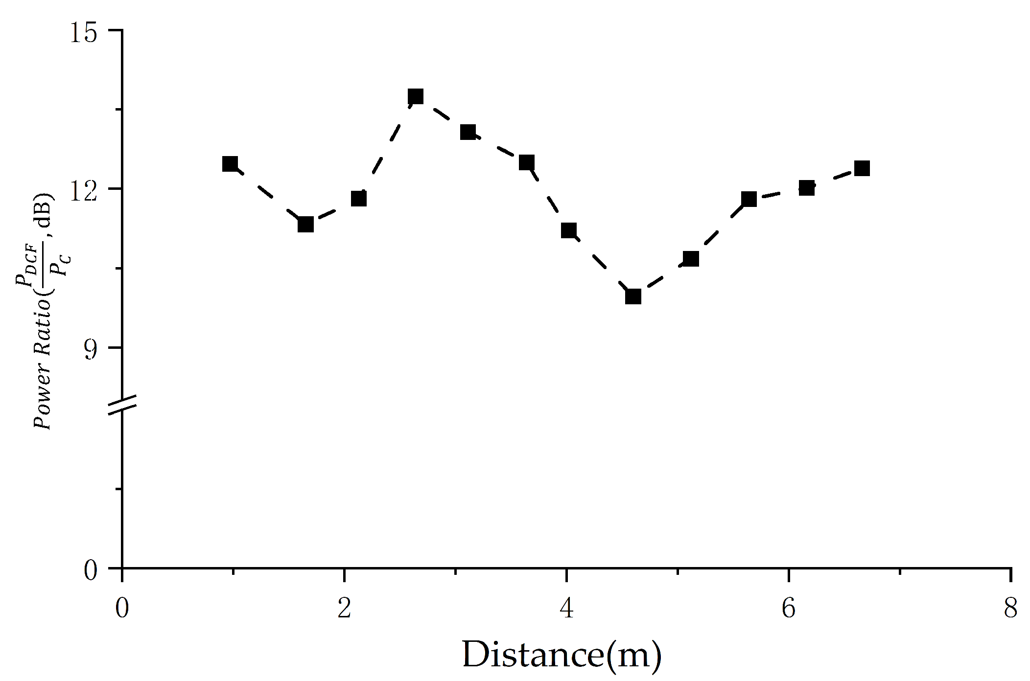
To directly compare a DCF receiver LiDAR with a conventional SMF circulator system under identical conditions, we measured echo power as the primary metric. A whiteboard with a reflectivity sticker served as the target, positioned at R = 0.97–6.68 m (distances calibrated by a laser range finder and limited by laboratory space). The transmit power, optics, FOV, and acquisition settings were kept identical across the two configurations.
As shown in
Figure 3, the DCF-based system yields >10 dB higher received echo power than the SMF circulator over the tested range, exceeding the estimate from Equation (4). This improvement cannot be attributed to NA alone. For rough-surface returns, the spatial coherence is reduced, so the focused return spot at the receiver expands relative to the emitted beam. Consequently, the effective collection efficiency is governed not only by NA but also by the receiving aperture at Port O that can accept the expanded return. In this regime, the inner cladding of the DCF (≈105 μm) provides a substantially larger effective collection area than the SMF core (≈9 μm), which explains the observed >10 dB gain.
Figure 4a presents the system’s echo signal power, demonstrating a proportional relationship to 1/R
2, consistent with (2). From this figure, a fitting function has been derived as follows:
The measurements of the signal-to-noise ratio (SNR) are presented in
Figure 4b. According to (5), it is projected that at a distance of 70.7 m, the system will maintain a signal-to-noise ratio (SNR) of 3 dB. Consequently, this distance is deemed to represent the current maximal operational range of the system.
Although (2) indicates that the received power increases as the target approaches, at excessively short ranges the spot at the receiver enlarges, causing overfill mismatch so that part of the return is not effectively collected (see
Table 1).
Figure 5 shows that at R = 20 cm the system SNR drops to 3.47 dB. To retain a safety margin, we regard 20 cm as the minimum detectable range of the system.
To evaluate the ranging precision and accuracy of the system, measurements were performed at 0.5 m intervals, resulting in 14 sets of tests. Ranging precision refers to the uncertainty stemming from random errors in measurement, independent of the true distance. It is quantified using the standard deviation of the measurement data. On the other hand, accuracy indicates the deviation of the measured value from the true value. To mitigate random errors, each measured value represents the mean of 1000 measurements taken at the same distance. The true value for comparison is acquired using a laser range finder.
Figure 6 displays the test results. The maximum precision error is 3.4 cm, while the maximum accuracy error reaches 5.1 cm. The observation reveals a correlation where the error increases as the echo signal strength decreases, which is caused by the walk error of the pulse signal [
21].
To evaluate the scanning performance of this system, three highly reflective objects were positioned at distances of 0.7 m, 2.25 m, and 3.7 m. The echo signals obtained from the scan were processed in real-time for distance determination using LabVIEW software (ver. 2024 Q1), with the outcomes presented in
Figure 7. Analysis of these results indicates an increase in error, which can be attributed to the rotation of the galvanometer.
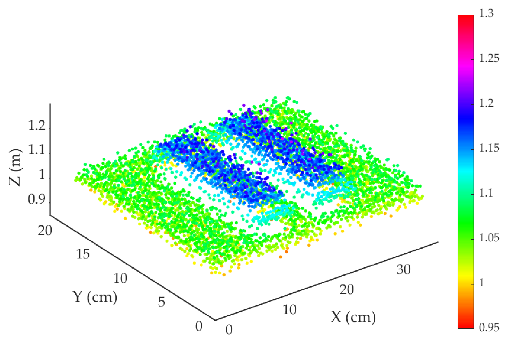
Figure 8 shows the 3D scanning performance, we placed a cardboard panel with two rectangular apertures of 6 × 12 cm at 1.05 m from the scanner and a second cardboard panel at 1.15 m. The galvanometer scanned a 20° × 10° field of view with a 100 Hz fast axis and a 3.3 Hz slow axis, producing a 200 × 30 pixel raster. The reconstruction shows larger errors at 1.15 m than at 1.05 m, which we attribute to reduced echo strength and the resulting increase in amplitude-dependent walk error [
28].


