Abstract
To address the issues of insufficient detector target size and high system complexity in infrared bionic compound-eye systems, this paper designs a miniaturized cooled medium-wave infrared curved bionic compound-eye optical system specifically for large target surface detectors and develops a proof-of-concept prototype for verification. The system comprises three components: (1) a curved multi-aperture array, which consists of 61 sub-apertures with an entrance pupil diameter of 5 mm and a focal length of 10 mm; (2) a cooled planar detector; and (3) a relay imaging system, which adopts secondary imaging technology and achieves the matching between the array and detector with only six infrared lenses. The fill factor is introduced to analyze light energy utilization efficiency, providing a theoretical basis for improving the system’s signal-to-noise ratio and spatial information collection capability; meanwhile, the focal length distribution and pupil matching are analyzed to ensure the system’s optical performance. The system operates within the 3.7–4.8 μm wavelength band, with a total focal length of 3.08 mm, F-number of 2, and field of view reaching 108°. Simulations demonstrate that all sub-aperture imaging channels have MTF values greater than 0.47 at 33.3 lp/mm, with distortion less than 3%. Imaging test results verify that the system possesses excellent imaging performance.
1. Introduction
With the widespread application of optical technology in numerous fields, performance requirements for imaging systems are becoming increasingly demanding. Traditional single-aperture imaging systems struggle to simultaneously satisfy the needs for both a wide field of view (FOV) and high-resolution imaging. Furthermore, as the FOV increases, distortion escalates dramatically and becomes difficult to correct, resulting in severe edge distortion in images. While multi-camera arrays can circumvent the issue of large distortion and achieve wide-FOV high-resolution images, they have drawbacks, including a bulky system size, difficulties in matching between multiple cameras, and complex subsequent image processing [1]. Additionally, single-aperture systems require extremely high frame rates when capturing, locating, tracking, and identifying fast-moving targets. In contrast, bionic compound-eye imaging systems, by leveraging their multi-aperture cooperative imaging mechanism, can achieve equivalent functionality at lower frame rates, thereby effectively reducing system complexity.
Compound eyes are the visual organ of many arthropods, composed of numerous sub-apertures arranged in an orderly manner on a curved substrate. Due to advantages such as a wide FOV, compact size, high resolution, and sensitivity to moving targets [2], compound-eye visual systems show significant application potential in fields such as wide-area surveillance and medical imaging [3]. Inspired by this, researchers have developed bionic compound-eye systems by mimicking their multi-aperture structure and neural signal processing mechanisms [4]. Initially, constrained by fabrication techniques and technologies, research focused on planar bionic compound-eye systems, and their planar structure inherently limits FOV expansion [5]. With advances in flexible materials and manufacturing technologies, miniaturized, wide-FOV curved bionic compound-eye systems have gradually emerged as a mainstream research direction [6].
Curved bionic compound-eye systems have made significant progress in the visible band in recent years. A key challenge for curved bionic compound-eye systems lies in matching the curved multi-aperture array with a planar image detector. In 2017, Shi Chengyong et al. successfully addressed this problem by introducing a relay imaging system [7]. In 2020, Xu Huangrong et al. designed a curved compound-eye camera featuring 127 sub-apertures and a 98° FOV, achieving clear imaging of distant objects [8]. Subsequently, this team also realized multispectral imaging [9] and proposed a dual-biomimetic curved compound-eye camera capable of multi-target ranging [10]. These research results indicate that visible-light compound-eye systems have made substantial advancements in FOV expansion, multispectral imaging, and ranging. However, due to limitations in their operating band, they are difficult to apply in low-illumination environments, such as nighttime and smoke, and thus cannot meet the requirements of all-weather and all-environment monitoring.
To overcome the aforementioned application limitations, researchers have begun to expand the study of compound-eye systems to the infrared band in recent years. Nevertheless, the research on infrared compound-eye systems is still in the preliminary development stage, especially lacking experimental verification of actual imaging effects. In 2023, Fan Chen et al. designed an infrared dual-band common-path compound-eye optical system with a hexagonal band arrangement, improving spatial and light energy utilization efficiency [11]. However, the system is relatively complex, and the small detector target size (320 × 256 × 30 μm) hinders its ability to meet high-resolution imaging requirements. That same year, our research team successfully developed a wide-FOV cooled infrared curved bionic compound-eye optical system and a prototype for performance validation, and realized the imaging demonstration of an infrared compound-eye system for the first time [12,13]. Although the prototype’s imaging results effectively verify the correctness of the optical theoretical model, the bulky volume of the relay imaging system limits its application on platforms with constrained space payloads, such as micro unmanned aerial vehicles (UAVs) and vehicle-mounted auxiliary detection equipment. In contrast, this study has achieved significant breakthroughs in both system compactness and imaging performance: the finally implemented compound-eye imaging system achieves a compact optical volume of less than ϕ110 mm × 195 mm, featuring the advantage of miniaturization. Meanwhile, it has a large sub-aperture, a large relative aperture, and a large detector target size, all of which contribute to the enhanced spatial resolution and detection performance of the system.
To address the existing issues of current infrared compound-eye systems, this paper designs a miniaturized cooled medium-wave infrared curved bionic compound-eye optical system. The system comprises three components: a curved multi-aperture array, a relay imaging system, and an infrared cooled detector. By precisely aligning the system aperture stop with the detector cold stop, 100% cold-stop efficiency is achieved. This work establishes a curved circumferential array arrangement model that defines the calculation method for sub-aperture positions while analyzing the mutual constraints among key sub-aperture parameters. The fill factor, which characterizes light energy utilization efficiency, is theoretically derived and analyzed to provide a foundation for system parameter optimization. Furthermore, the matching between the curved multi-aperture array and the relay imaging system is investigated in detail, and overall system focal length distribution is implemented based on the dual optical group combination theory, ensuring the rationality of the optical design. Finally, to verify the actual imaging performance of the system, a prototype is developed based on the proposed design scheme, and imaging tests are conducted. The developed compound-eye imaging system offers multi-aperture cooperative detection capabilities that improve dynamic range, increase scene information acquisition, and enhance overall imaging quality. These characteristics make it particularly suitable for all-weather multi-target detection and recognition in complex environments, UAV surveillance, and other similar application scenarios.
2. Design Theory of Bionic Compound-Eye System
2.1. Sub-Aperture Arrangement Position
The biological compound eye consists of numerous sub-apertures densely and orderly arranged, with its corresponding structure in the imaging system termed the multi-aperture array. This paper employs a curved circumferential arrangement model for array design. As shown in Figure 1, the array expands outward from the spherical vertex as the center, with radii progressively increasing.
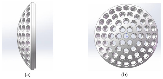
Figure 1.
Model diagram of curved circumferential array arrangement: (a) side view; (b) front view.
To precisely calculate the position of each sub-aperture within the array, a planar coordinate system is established, as illustrated in Figure 2. An XY coordinate system is set up with the central sub-aperture as the origin, where the coordinates of the central s sub-aperture are (0, 0). Given the angle between the optical axes of adjacent sub-apertures in the primary array direction, the position coordinates (x, y) of each sub-aperture can be determined through geometric calculation. These position coordinates correspond to the tilt angles defined in the X and Y directions within ZEMAX software (ZEMAX2019.4). Therefore, by setting the tilt angle values in the X and Y directions for each sub-aperture, the arrangement of the entire sub-aperture array can be completed.
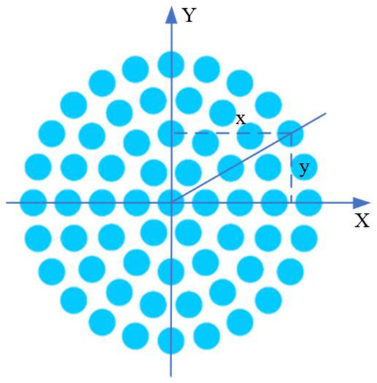
Figure 2.
Schematic diagram of sub-aperture planar angle in the compound-eye system.
2.2. Sub-Aperture Design Theory of Curved Bionic Compound-Eye Optical System
On the substrate of the curved circumferential arrangement model, the sub-aperture lenses adopt a unified design. Figure 3 shows a schematic diagram of the sub-aperture arrangement along a main array direction of the compound-eye system. Key system design parameters are defined as follows: the maximum FOV angle of the compound-eye system is , the FOV angle of a single sub-aperture is , the sub-aperture diameter is , the mechanical separation between adjacent sub-apertures is , the angle between the optical axes of adjacent sub-apertures is , the FOV overlap angle between adjacent sub-apertures is , the radius of the curved substrate is , the total number of sub-apertures in the compound-eye system is , and the number of arrangement layers is (the central sub-aperture is designated as layer 1).
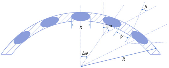
Figure 3.
Schematic diagram of sub-aperture arrangement along a main array direction of the compound-eye system.
Based on the structural characteristics of the curved circumferential arrangement model and the geometric relationship between the parameters, the following formulas can be derived:
Equation (4) indicates that when the design parameters satisfy , the FOVs of adjacent sub-apertures just cover the entire object space scene without imaging blind spots; when , an overlapping FOV region exists between adjacent sub-apertures, enabling the same target to be detected simultaneously by multiple sub-apertures, which confers the unique advantage of monocular multi-aperture observation. This paper’s design is required to satisfy this condition to improve imaging quality and the reliability of target recognition.
2.3. Fill Factor Study
Fill factor characterizes the light energy utilization efficiency and spatial information collection capability of a curved bionic compound-eye system. It is defined as the ratio of the sum of the effective light-passing areas of all sub-apertures on the curved substrate to the total area of the curved substrate [14].
Approximating a single sub-aperture as a circle with diameter , the total light-passing area of sub-apertures is
The curved substrate is a spherical cap, whose area is determined by the radius of curvature of the sphere and the height of the spherical cap:
Therefore, the fill factor can be expressed as
A larger value indicates a denser arrangement of sub-apertures on the curved substrate and higher spatial utilization efficiency of the compound-eye system. However, an excessively large may lead to image aliasing between sub-apertures or mutual crosstalk. Therefore, the fill factor cannot be too large and requires comprehensive consideration. The fill factor is constrained by multiple parameters, analyzed as follows:
- (1)
- Sub-aperture and mechanical separation between adjacent sub-apertures:
Since , increasing is the most effective way to increase . Simultaneously, reducing allows arranging more or using a larger on a fixed substrate area, thereby increasing . However, the minimum value of is constrained by lens edge thickness, assembly tolerances, and the need to prevent mechanical interference between adjacent sub-apertures.
- (2)
- Number of sub-apertures :
Increasing also increases . However, as discussed in Section 2.2, is constrained by the total FOV angle and the requirement for FOV overlap between adjacent sub-apertures.
- (3)
- Geometric parameters and of the curved substrate:
The spherical cap height and the system semi-FOV angle satisfy . Substituting this into Equation (7) yields . This indicates that, under the premise of satisfying optical design feasibility and manufacturing constraints, selecting a smaller is an effective way to increase .
- (4)
- Angle between adjacent sub-aperture optical axes:
Decreasing allows arranging more or using a larger for the same total FOV angle, thereby increasing . However, with fixed and , decreasing usually implies increasing , which causes to decrease. Furthermore, as discussed in Section 2.2, decreasing reduces the total system FOV but simultaneously increases the FOV overlap ratio between adjacent sub-apertures. Therefore, optimizing this parameter requires comprehensive consideration based on specific application scenarios and algorithmic requirements.
3. Design of Curved Bionic Compound-Eye Optical System
3.1. Overall Design Specifications
The curved bionic compound-eye optical system designed in this paper primarily consists of three components: a curved multi-aperture array arranged using a circumferential array model, a relay imaging system for image plane transformation, and an infrared cooled detector for image reception. This detector has a resolution of 1280 × 1024 and a pixel size of 15 μm. Table 1 lists the specifications required for the compound-eye optical system.

Table 1.
Specifications of the compound-eye optical system.
Based on target detection requirements, the total focal length of the system is calculated according to Equation (8):
where is the detector pixel size (); the detection distance specified in the requirements is ; and the ground sample distance is . Substituting these parameters yields a calculated focal length of 3 mm. Therefore, the system focal length must satisfy .
Based on the mutual constraints among the sub-aperture parameters discussed in Section 2.2 and the above design specifications, calculations and parameter selections are conducted to determine the overall design parameters of the curved bionic compound-eye system, as listed in Table 2.

Table 2.
Overall design parameters of the compound-eye optical system.
3.2. Curved Multi-Aperture Array Design
3.2.1. Single Sub-Aperture Design
Based on the aforementioned theory, the design parameters for a single sub-aperture are analyzed and selected. The final parameters are listed in Table 3.

Table 3.
Design parameters of a single sub-aperture.
The designed optical system for a single sub-aperture consists of three lenses, with the lens materials selected as commonly used zinc sulfide (ZnS), silicon (Si), and chalcogenide IRG-series glass. The outer diameter of each sub-aperture is 8 mm, and the weight of a single sub-aperture is 1.32 g. The optimized optical path diagram of a single sub-aperture is shown in Figure 4.
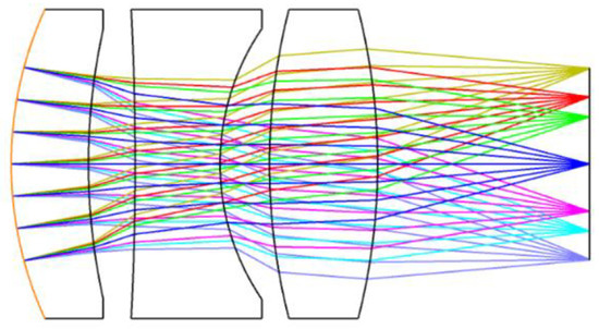
Figure 4.
Optical path diagram of a single sub-aperture.
The modulation transfer function (MTF) is used to evaluate the image quality of the optical system. Based on the detector pixel size, the Nyquist frequency of the system is calculated as . The MTF curve of the sub-aperture optical system is shown in Figure 5. At the spatial frequency of 33.3 lp/mm, the MTF values across all FOVs are close to the diffraction limit, indicating that the system achieves diffraction-limited resolution.
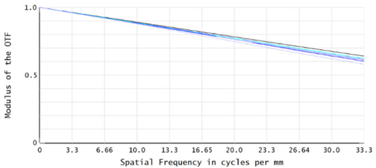
Figure 5.
MTF curve of the sub-aperture optical system.
3.2.2. Construction of Curved Multi-Aperture Array
The designed individual sub-apertures are arranged on a curved substrate according to the curved circumferential arrangement model, forming the curved multi-aperture array. Each sub-aperture has the same focal length, and the curved focal surface images they form are concentric with the substrate. Figure 6 shows the physical model diagram of the curved multi-aperture array. As illustrated, the array consists of a five-layer circumferential annular structure, with 9 sub-apertures along the primary array direction, totaling 61 sub-apertures for the entire array. Calculation using Equation (2) shows that the curved multi-aperture array is arranged on a curved substrate with a radius of curvature of 75 mm. The axial length of each sub-aperture is 15 mm; consequently, the curved focal surface image formed by the curved multi-aperture array is distributed on a curved surface with a radius of curvature of 60 mm.
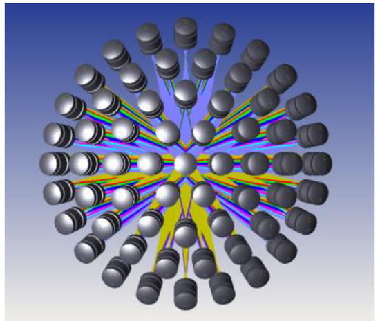
Figure 6.
Physical model diagram of the curved multi-aperture array.
3.3. Relay Imaging System Design
In the design of the bionic compound-eye system, the primary role of the relay imaging system is to perform image plane transformation: converting the curved focal surface image formed by the curved multi-aperture array into a focal plane image to match the planar detector for image reception and processing. Additionally, the relay imaging system can correct optical aberrations to yield better imaging quality. The relay imaging system must be designed based on the curved multi-aperture array and satisfy the following requirements [15]:
- Object-image curvature matching principle: The radius of curvature of the object surface of the relay imaging system should match the radius of curvature of the image surface of the curved multi-aperture array;
- Beam integrity principle: The aperture of the object surface of the relay imaging system should be greater than or equal to the aperture of the focal surface of the curved multi-aperture array to ensure that all light rays emitted by the multi-aperture array can be received by the relay imaging system.
The compound-eye optical system is designed by combining the individually designed single sub-aperture and relay imaging system. Therefore, the overall compound-eye optical system is regarded as a dual optical group combination system, where the single sub-aperture is the first optical group and the relay imaging system is the second optical group. The formula for calculating the focal length of the overall compound-eye optical system is the following:
where is the focal length of the first optical group, is the focal length of the second optical group, and is the optical interval between the two groups, defined as the distance between the image-side focal plane of the first group and the object-side focal plane of the second group. According to the system design requirements, the overall focal length of the compound-eye optical system must satisfy . From Section 3.2.1, the sub-aperture focal length . Considering the relay imaging system adopts secondary imaging technology, substitution into the above equation yields the following:
The relay imaging system is a finite conjugate imaging system. Let its FOV angle be , and the detector target size be . Its imaging relationship must satisfy the following:
The detector target size . Based on the sub-aperture design results, the incident FOV angle at the relay imaging system entrance from the sub-aperture spherical shell is calculated as . Substituting into the above equation gives the following focal length requirement for the relay imaging system:
Guided by the two constraints (10) and (12), the relay imaging system is designed, with its key parameters detailed in Table 4.

Table 4.
Design parameters of the relay imaging system.
In optical system design, compared to spherical lenses, the polynomial coefficients in aspheric surfaces provide more degrees of freedom for optical system design. This characteristic enables aspheric surfaces to effectively correct aberrations to meet global imaging quality requirements for large target surfaces, while simultaneously reducing the number of lenses to achieve a lightweight and miniaturized system. Ultimately, this approach yields optimal imaging performance with fewer optical elements. Leveraging this advantage, high-order aspheric surfaces are introduced on the rear surface of the first lens, the front surface of the third lens, and the front surface of the fourth lens in the relay imaging system. This introduction corrects aberrations, improves imaging quality, reduces the number of lenses, and optimizes the system structure.
The final optical path diagram of the relay imaging system is shown in Figure 7. The system is constructed using three infrared optical materials: silicon (Si), germanium (Ge), and calcium fluoride (CaF2). Employing only six infrared lenses, it achieves a large target size with a resolution of 1280 × 1024 and a pixel size of 15 μm, successfully compatible with the cooled infrared detector featuring a large relative aperture with an F-number of 2.
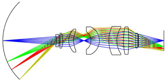
Figure 7.
Optical path diagram of the relay imaging system.
This system is a wide-angle optical system employing a secondary imaging structure, which provides an intermediate image plane. Its front group is primarily responsible for converging wide-angle large-FOV beams and performing preliminary aberration correction, while its rear group further corrects residual aberrations. Simultaneously, the front and rear groups exhibit a quasi-symmetric configuration relative to the intermediate image plane. This configuration facilitates aberration balancing, reduces ray deflection discrepancies, and suppresses the accumulation of asymmetric aberrations. Adopting this structure is advantageous for achieving pupil matching between the entrance pupil of the relay imaging system and the exit pupil of the curved multi-aperture array. It also facilitates the coincidence of the exit pupil of the relay imaging system and the cold stop of the cooled detector, thereby achieving 100% cold-stop efficiency. Furthermore, this approach reduces the aperture and volume of the relay imaging system. Under the design parameters of a 96° large FOV and 15 mm focal length, the maximum lens aperture is less than 30 mm, and the system length is only 120 mm.
The MTF diagram of the relay imaging system is shown in Figure 8. The MTF values across all FOVs are greater than 0.46 at the characteristic frequency of 33.3 lp/mm, meeting the imaging quality requirements.
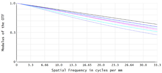
Figure 8.
MTF curve of the relay imaging system.
3.4. Overall Bionic Compound-Eye Optical System Design
When integrating the designed curved multi-aperture array with the relay imaging system, the pupil connection principle must be followed to ensure favorable imaging performance for the overall system. This requires the exit pupil position of the curved multi-aperture array to coincide with the entrance pupil position of the relay imaging system. After integration, the system forms a complete compound-eye optical system, and the aberrations of the entire optical path are comprehensively optimized and balanced to ensure the image quality of all sub-apertures meets the design requirements. The physical model of the optimized compound-eye optical system is shown in Figure 9.
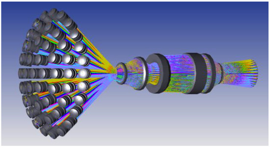
Figure 9.
Physical model diagram of the compound-eye optical system.
The FOV of the multi-aperture bionic compound-eye optical system is formed by stitching together the FOVs of individual sub-apertures. Therefore, image quality analysis is required for different sub-aperture channels. Since all sub-aperture parameters are identical and the entire system possesses rotational symmetry, only the imaging quality of five sub-aperture channels along a primary array direction (as illustrated in Figure 10) is analyzed below. The rotation angles of the optical axes of these sub-aperture optical systems relative to the optical axis of the central sub-aperture are 0°, 10°, 20°, 30°, and 40°, respectively.
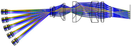
Figure 10.
Optical path diagram of the compound-eye optical system.
Figure 11, Figure 12, Figure 13, Figure 14 and Figure 15 display the MTF curves for each sub-aperture channel at the characteristic frequency of 33.3 lp/mm. As shown in the figures, the MTF curves all approach the diffraction limit. This demonstrates that the designed compound-eye system achieves good imaging quality both on-axis and at the edge, satisfying the design requirements.
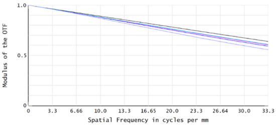
Figure 11.
MTF curve diagram of the central sub-aperture imaging channel.
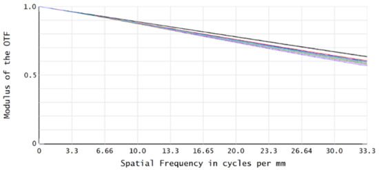
Figure 12.
MTF curve diagram of the 10° sub-aperture imaging channel.
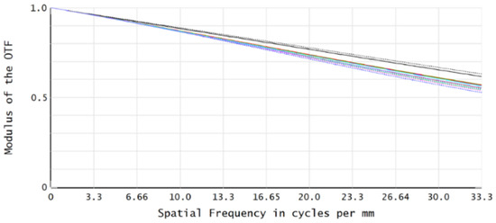
Figure 13.
MTF curve diagram of the 20° sub-aperture imaging channel.
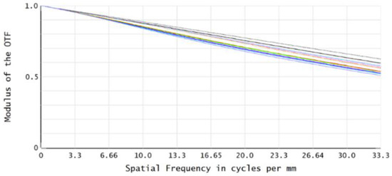
Figure 14.
MTF curve diagram of the 30° sub-aperture imaging channel.
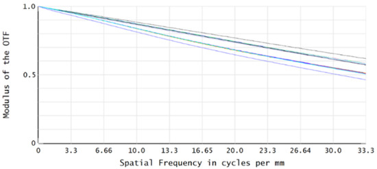
Figure 15.
MTF curve diagram of the edge sub-aperture imaging channel.
Additionally, the root mean square (RMS, used to quantify the extent of ray dispersion on the image surface) radius, field curvature, and distortion for all sub-aperture channels are analyzed. The analysis results demonstrate that the RMS spot radius of all sub-aperture channels is smaller than the Airy disk radius across varying FOVs; the field curvature of all sub-aperture channels is less than 15 μm, and the distortion is less than 3%. These analytical results collectively indicate that this compound-eye system possesses excellent imaging quality.
Compared to traditional single-aperture wide-angle lenses (such as the 102° wide-FOV industrial endoscope designed in reference [16], which exhibits a maximum distortion of 24.5%), the system in this paper demonstrates unique advantages: while achieving 108° wide-FOV imaging, it exhibits very low distortion, effectively suppressing image distortion in the edge FOV. This is attributed to the multi-aperture advantage inherent in compound-eye imaging systems. The entire wide FOV is partitioned into multiple small-FOV angular regions, with each region imaged by an independent sub-aperture unit. Each sub-aperture unit essentially acts as an independent imaging system with a small-FOV and small aperture. According to the fundamental principles of geometrical optics, the optical distortion of a small-FOV system is significantly less than that of a large-FOV system. Consequently, the compound-eye imaging system overcomes the severe distortion problem encountered by traditional single-aperture systems in large-FOV applications.
4. Athermalization Analysis
To ensure the imaging stability of the bionic compound-eye optical system within the operating temperature range of 0~40 °C, an athermalization analysis has been conducted in this study. The system adopts a passive athermalization compensation method, where slight adjustments to the detector position are made to offset the focal shift caused by thermal effects, thereby maintaining imaging quality.
Figure 16 and Figure 17 display the MTF curves of the central and edge sub-aperture channels of the compound-eye optical system at 0 °C and 40 °C, respectively. The analysis results indicate that at the characteristic frequency of 33.3 lp/mm, the MTF values of all sub-aperture channels remain above 0.45 across different temperatures, approaching the diffraction cinlimit, and remain stable throughout the operating temperature range. This demonstrates that the system exhibits good thermal adaptability and imaging stability, capable of meeting the requirements of practical application environments.

Figure 16.
MTF curve diagram of the central sub-aperture imaging channel: (a) 0 °C; (b) 40 °C.

Figure 17.
MTF curve diagram of the edge sub-aperture imaging channel: (a) 0 °C; (b) 40 °C.
5. Cold-Reflection Analysis
Cold reflection is a stray radiation phenomenon in cooled infrared optical systems caused by thermal radiation differences. It arises from the significant temperature gradient between the cryogenic chamber of the operating cooled detector and the ambient-temperature components of the optical system. Its artifact manifests as a fixed-position dark spot in the image [17], severely degrading the system signal-to-noise ratio and target recognition capability. The intensity of cold reflection can be quantified using the Narcissus Integral Coefficient (YNI) and the Incidence Ratio (I/IBAR) [18].
For the previously optimized relay imaging system, it is first inverted in ZEMAX software, as shown in Figure 18.
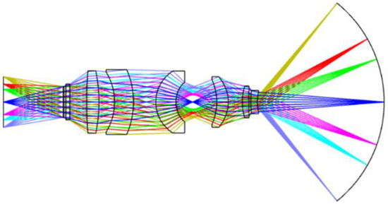
Figure 18.
Optical path diagram of the inverted relay imaging system.
Subsequently, the NARCISSUS macro in ZEMAX is used to perform numerical analysis of cold reflection. The YNI and I/IBAR values for each optical surface of the relay imaging system are obtained and listed in Table 5. It should be noted that the object plane, image plane, and stop plane have been excluded from the table; only the optical surfaces of the system are retained.

Table 5.
YNI and I/IBAR values for all optical surfaces of the relay imaging system.
When |YNI| > 1 for a given optical surface, it indicates minimal cold-reflection impact from that surface. Other surfaces require further analysis: reverse ray tracing is performed to observe whether reflected rays cause significant imaging degradation. According to Table 5, surfaces 10 and 16 require reverse ray tracing. The ray tracing diagrams are shown in Figure 19. The results show that a very small amount of reflected rays from surface 10 returns to the detector focal plane but does not converge to form an image; the cold-reflection rays generated by surface 16 are divergent and do not affect imaging. Therefore, the cold-reflection phenomenon in this relay imaging system has a negligible impact on imaging. This further demonstrates that the design of this relay imaging system provides significant cold-reflection suppression, satisfying the system design requirements.
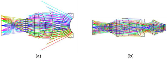
Figure 19.
Reverse ray tracing diagrams for surfaces 10 and 16 of the relay imaging system: (a) Surface 10; (b) Surface 16.
6. Tolerance Analysis
Tolerance analysis is a critical step in evaluating the manufacturing difficulty and assembly precision of an optical system. Its purpose is to systematically assess the impact of manufacturing and alignment errors on optical system performance, thus requiring the definition of reasonable tolerance ranges for parameters such as lens curvature radius, thickness, and decenter. Unlike traditional single-aperture optical systems, the compound-eye optical system consists of multiple independent sub-aperture channels, resulting in greater complexity in tolerance analysis. This complexity manifests in two aspects: First, in addition to controlling the manufacturing and assembly tolerances of components within each sub-aperture channels, the relative positional tolerances between sub-aperture channels must also be strictly controlled. Second, regarding evaluation criteria, it is necessary not only to assess the imaging quality of individual sub-aperture channels but also to comprehensively evaluate the imaging quality of all sub-aperture channels to ensure the quality of the final stitched image satisfies design requirements. Table 6 lists the tolerance allocation table for the compound-eye system. Most lenses meet practical fabrication requirements based on these tolerances. However, for certain sensitive parameters, secondary tolerance allocation is necessary. For instance, the curvature radius tolerance for the first lens of the relay imaging system is ±2 fringes, and the thickness tolerance is ±0.01 mm.

Table 6.
Tolerance assignment table for the compound-eye system.
Using ZEMAX software, tolerance analysis for the compound-eye system is performed via the sensitivity analysis method, with the RMS spot radius serving as the tolerance sensitivity evaluation criterion. Monte Carlo analysis is employed for random simulation at the spatial frequency of 33.3 lp/mm. Two hundred Monte Carlo sampling analyses are conducted for each sub-aperture channel. This paper lists only the tolerance analysis results for the central sub-aperture imaging channel and an edge sub-aperture imaging channel, as presented in Table 7 and Table 8, respectively.

Table 7.
Monte Carlo tolerance analysis results of the central sub-aperture imaging channel.

Table 8.
Monte Carlo tolerance analysis results of the edge sub-aperture imaging channel.
The data above indicate that the variation in RMS spot radius after tolerance analysis is small. Compared to the central sub-aperture channel, the variation in the edge sub-aperture channel is slightly larger but still maintains a favorable imaging level. Therefore, it is concluded that the tolerance analysis results for the bionic compound-eye system are reasonable, indicating that the optimized tolerance allocation ensures the system maintains excellent imaging quality under actual manufacturing conditions.
7. System Assembly and Adjustment Process
During the alignment of the 61 sub-apertures, each sub-aperture lens in the curved multi-aperture array of this system adopts a standard spherical design, which effectively reduces the machining difficulty of individual lenses and enhances the overall consistency of the array. After machining, a final consistency verification is performed on the spherical shell, which includes re-measuring the radius of curvature, center thickness, and other parameters of each sub-aperture lens to prevent deviations in individual lens parameters from affecting the imaging consistency of the array; simultaneously, re-measuring the central coordinates and surface profile accuracy of the 61 sub-aperture mounting holes to ensure precise arrangement and common-benchmark assembly of the multi-aperture array.
In the overall system assembly process, a multi-step iterative alignment strategy is adopted, with the specific workflow as follows:
- Parameter re-measurement: Before alignment, re-measure all key components, such as parameters of the curved spherical shell and critical dimensions of lens barrels and spacers, to avoid introducing assembly deviations due to errors in structural parts;
- Multi-aperture array installation: Complete the assembly of the sub-aperture lenses first, and then install each sub-aperture lens one by one into the corresponding mounting holes on the spherical shell;
- Relay imaging system installation and preliminary adjustment: Install the relay imaging system, and preliminarily adjust its relative distance and tilt angle with respect to the spherical shell to achieve initial optical path alignment;
- Detector rough adjustment: Secure the detector to the base, and adjust its position and orientation to achieve preliminary alignment between the center of the detector target plane and the optical exit pupil center;
- System coaxial precision adjustment and image plane optimization: Iteratively adjust the relative positions and angles of the spherical shell, relay imaging system, and detector. Finally, fine-tune the detector position to the optimal image plane and secure it firmly.
8. Imaging Test and Analysis
To validate the imaging performance of the designed curved bionic compound-eye optical system, a prototype is fabricated according to the aforementioned design scheme. Figure 20 and Figure 21 show the curved substrate spherical shell diagram and the overall assembly diagram of the compound-eye system prototype, respectively. To comprehensively evaluate the system performance, laboratory testing and field testing are conducted to validate the system’s performance in multiple dimensions, including FOV coverage, distortion control, thermal sensitivity, and dynamic target detection. All experimental images are captured by the prototype, ensuring the authenticity and reliability of the verification results.
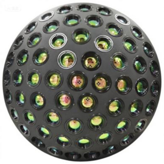
Figure 20.
Spherical shell diagram of the curved substrate.
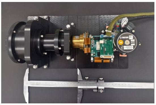
Figure 21.
Overall assembly diagram of the compound-eye system.
8.1. Laboratory Testing
- (1)
- Verification of FOV coverage and multi-channel cooperative detection
To validate the multi-channel cooperative detection capability and FOV coverage effectiveness of the compound-eye system, a black-and-white checkerboard is used as the target. The target is placed along the system’s optical axis (0°) and at off-axis angles of 10° and 30° for imaging, and the results are shown in Figure 22. As observed, when the target is positioned at 0°, imaging is primarily achieved clearly by the central sub-aperture channels. When the target is shifted to 10° and 30°, the images are captured by the edge sub-aperture channels corresponding to the respective FOV directions. This result visually demonstrates that targets at different spatial orientations are responded to by different channels, confirming the system’s multi-aperture cooperative detection mechanism and effective large FOV coverage. This provides a foundation for subsequent multi-channel image fusion and target localization.

Figure 22.
Imaging results of the black-and-white checkerboard target at different azimuth angles: (a) on the optical axis (0°); (b) off-axis 10° direction; (c) off-axis 30° direction.
- (2)
- Verification of distortion control performance
A laboratory scene is captured by the compound-eye system, and the result is shown in Figure 23. Straight structures in the image, such as ceiling lines and bookshelf edges, remain straight even at the edge of the FOV, with no significant barrel or pincushion distortion observed. To highlight the advantages of the proposed system, a comparison is made with an image captured by an existing single-aperture medium-wave infrared wide-angle airborne lens with a 108° × 90° FOV (Figure 24). The comparison reveals that the image from the single-aperture lens exhibits noticeable straight-line distortion at the edge of the FOV, whereas the compound-eye system demonstrates superior distortion control capability while maintaining a large FOV.
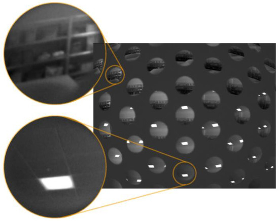
Figure 23.
Laboratory scene image captured using the compound-eye system.
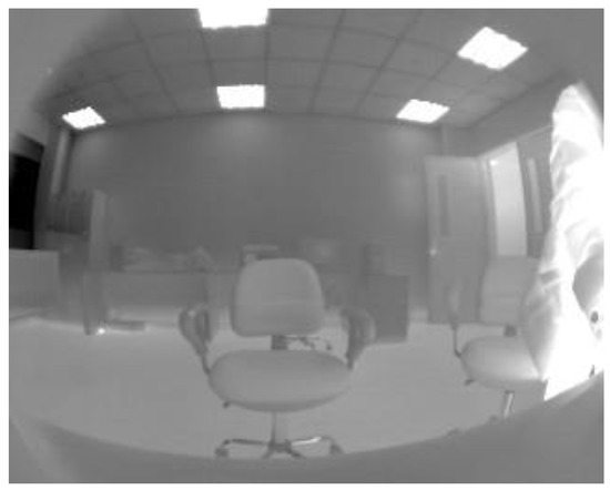
Figure 24.
Laboratory scene image captured using a single-aperture medium-wave infrared wide-angle airborne lens.
- (3)
- Thermal sensitivity test
To assess the system’s sensing capability in real thermal environments, an infrared thermal imaging experiment based on temperature-difference targets is conducted. A standard blackbody serves as the target, with temperature differences between the target and the background set to 10 K and 30 K, respectively. The imaging results are presented in Figure 25. Under the 30 K temperature difference condition, the target area exhibits significantly higher brightness compared to the 10 K condition. Even at a 10 K difference, the target remains clearly distinguishable from the background. This result demonstrates that the system can effectively discriminate thermal targets of different intensities, exhibiting good thermal sensitivity. It meets the performance requirements of cooled infrared detectors and confirms the system’s suitability for target detection in complex thermal environments.
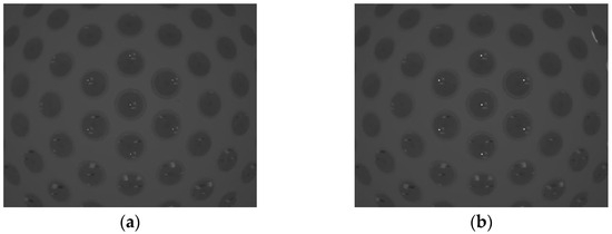
Figure 25.
Imaging results of the standard blackbody target under different temperature differences: (a) ΔT = 10 K; (b) ΔT = 30 K.
8.2. Field Testing
- (1)
- Verification of multi-channel FOV overlap
To verify the multi-channel FOV overlap characteristics of the compound-eye system, the prototype is placed on a laboratory windowsill to capture images of an outdoor building scene. Meanwhile, a comparative image with an FOV basically consistent with that of the central sub-aperture (to simulate the FOV characteristics of a single sub-aperture) is also captured. The results are shown in Figure 26. It can be observed from the figure that in the original infrared image captured by the compound-eye system, each sub-aperture only images a small local FOV; meanwhile, significant FOV overlap exists between the sub-images of adjacent sub-apertures, and targets such as the same building wall can be detected by multiple sub-apertures simultaneously. This FOV overlap design effectively avoids blind spots in image detection and can significantly improve the sensitivity and accuracy of target detection compared to traditional single-aperture imaging systems.
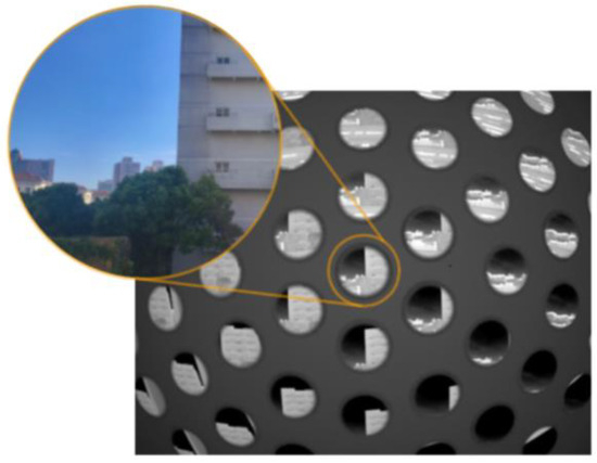
Figure 26.
Outdoor building scene captured using the compound-eye system.
- (2)
- Dynamic scene imaging test
To further verify the practicality of the system in complex environments, the prototype is placed in the school gate area to capture dynamic targets such as pedestrians and vehicles. The results are shown in Figure 27. It can be observed from the images that high-temperature areas such as vehicle engines show high-contrast bright regions due to significant temperature differences from the background, with clearly distinguishable contours. The movement trajectories of pedestrians appear continuous, without motion blur. The results demonstrate that the system possesses good dynamic target capture capability and temperature discrimination ability, indicating its potential for applications in security surveillance, intelligent transportation, and other fields.
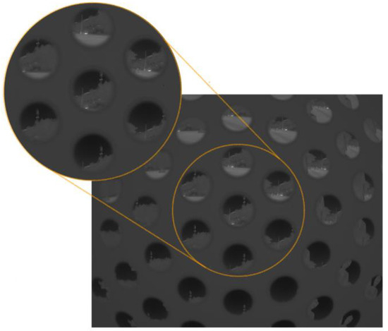
Figure 27.
Image of pedestrians and vehicles at the school gate captured using the compound-eye system.
9. Results
A miniaturized cooled medium-wave infrared curved bionic compound-eye optical system is designed in this paper for long-distance target imaging. To address the mismatch between the curved focal surface image formed by the curved multi-aperture array and the planar image detector, a relay imaging system is introduced. This relay imaging system adopts a secondary imaging structure, with front and rear groups that are quasi-symmetric relative to the intermediate image plane. This configuration facilitates aberration balancing and pupil matching, while reducing both optical system volume and weight. Furthermore, the incorporation of high-order aspheric surfaces effectively corrects aberrations, significantly improves imaging quality, and simplifies the system structure. By positioning the system exit pupil at the detector cold stop, 100% cold-stop efficiency is achieved, effectively suppressing stray radiation and enhancing the system signal-to-noise ratio.
The designed compound-eye system exhibits excellent imaging performance, with MTF values exceeding 0.47 at the spatial frequency of 33.3 lp/mm across all sub-aperture imaging channels, and optical distortion less than 3% throughout the full field. Compared to traditional single-aperture lenses, this system achieves large-FOV imaging while significantly reducing distortion. Subsequent cold-reflection analysis and tolerance analysis further verify that the system meets imaging quality requirements, demonstrating strong detection capability and resistance to cold-reflection artifacts.
Finally, imaging tests confirm that this compound-eye system features advantages in multi-aperture cooperative detection, significantly better distortion control than traditional single-aperture systems, and high thermal sensitivity, enabling effective multi-target acquisition in complex environments. The system holds broad application prospects in fields such as high-altitude wide-area ground surveillance and positioning and tracking fast-moving targets.
Author Contributions
Conceptualization, S.G. and Y.Y.; methodology, F.W. and Y.Y.; software, F.W., Y.C. and Y.Z.; formal analysis, F.W. and L.L.; investigation, K.M. and N.C.; resources, S.G., K.M. and N.C.; data curation, F.W., L.L. and Y.Y.; writing—original draft preparation, F.W.; writing—review and editing, Y.Y., S.G. and K.M.; visualization, L.L.; supervision, S.G., Y.Y. and K.M. All authors have read and agreed to the published version of the manuscript.
Funding
This research was funded by the Opening Project of Shanghai Key Laboratory of Crime Scene Evidence, grant number 2024XCWZK01.
Data Availability Statement
The data underlying the results presented in this paper are not publicly available at this time but may be obtained from the authors upon reasonable request.
Conflicts of Interest
The authors declare no conflicts of interest.
References
- Wilburn, B.; Joshi, N.; Vaish, V.; Talvala, E.-V.; Antunez, E.; Barth, A.; Adams, A.; Horowitz, M.; Levoy, M. High performance imaging using large camera arrays. ACM Trans. Graph. 2005, 24, 765–776. [Google Scholar] [CrossRef]
- Cao, A.; Wang, J.; Pang, H.; Zhang, M.; Shi, L.; Deng, Q.; Hu, S. Design and fabrication of a multifocal bionic compound eye for imaging. Bioinspiration Biomim. 2018, 13, 026012. [Google Scholar] [CrossRef] [PubMed]
- Zhang, S.; Wu, Q.; Liu, C.; Wang, T.; Zhang, H.; Wang, J.; Ding, Y.; Chi, J.; Xu, W.; Xiang, Y. Bio-inspired spherical compound eye camera for simultaneous wide-band and large field of view imaging. Opt. Express 2022, 30, 20952–20962. [Google Scholar] [CrossRef] [PubMed]
- Song, Y.M.; Xie, Y.; Malyarchuk, V.; Xiao, J.; Jung, I.; Choi, K.-J.; Liu, Z.; Park, H.; Lu, C.; Kim, R.-H. Digital cameras with designs inspired by the arthropod eye. Nature 2013, 497, 95–99. [Google Scholar] [CrossRef] [PubMed]
- Tanida, J.; Kumagai, T.; Yamada, K.; Miyatake, S.; Ishida, K.; Morimoto, T.; Kondou, N.; Miyazaki, D.; Ichioka, Y. Thin observation module by bound optics (TOMBO): An optoelectronic image capturing system. In Proceedings of the Optics in Computing 2000, Québec City, QC, Canada, 18–23 June 2000; pp. 1030–1036. [Google Scholar]
- Floreano, D.; Pericet-Camara, R.; Viollet, S.; Ruffier, F.; Brückner, A.; Leitel, R.; Buss, W.; Menouni, M.; Expert, F.; Juston, R. Miniature curved artificial compound eyes. Proc. Natl. Acad. Sci. USA 2013, 110, 9267–9272. [Google Scholar] [CrossRef] [PubMed]
- Shi, C.; Wang, Y.; Liu, C.; Wang, T.; Zhang, H.; Liao, W.; Xu, Z.; Yu, W. SCECam: A spherical compound eye camera for fast location and recognition of objects at a large field of view. Opt. Express 2017, 25, 32333–32345. [Google Scholar] [CrossRef]
- Xu, H.; Zhang, Y.; Wu, D.; Zhang, G.; Wang, Z.; Feng, X.; Hu, B.; Yu, W. Biomimetic curved compound-eye camera with a high resolution for the detection of distant moving objects. Opt. Lett. 2020, 45, 6863–6866. [Google Scholar] [CrossRef] [PubMed]
- Yu, X.; Liu, C.; Zhang, Y.; Xu, H.; Wang, Y.; Yu, W. Multispectral curved compound eye camera. Opt. Express 2020, 28, 9216–9231. [Google Scholar] [CrossRef] [PubMed]
- Liu, Y.; Xu, H.; Zhang, Y.; Wu, D.; Zhou, X.; Meng, Q.; Wang, Y.; Yu, W. Dual-biomimetic curved compound-eye camera system for multi-target distance measurement in a large field of view. Opt. Express 2024, 32, 41870–41881. [Google Scholar] [CrossRef] [PubMed]
- Fan, C.; Liu, J.; Gao, M.; Lv, H. Hexagonal bandarrangement common optical path compound eye optical system design. Chin. Opt. 2023, 16, 158–173. [Google Scholar]
- Yu, Y.; Chi, Y.H.; Li, L.H.; Wang, X.Y.; Chen, J.; Yue, J.; Gu, Y.Z.; Su, H.F.; Gao, S.L. Design of cooled infrared bionic compound eye optical system with large field-of-view. In Proceedings of the Earth and Space: From Infrared to Terahertz (ESIT 2022), Nantong, China, 17–19 September 2022; pp. 172–182. [Google Scholar]
- Wang, X.; Li, L.; Chi, Y.; Liu, J.; Yue, J.; Gao, S.; Yuan, X.; Yu, Y. Research on key technology of cooled infrared bionic compound eye camera based on small lens array. Sci. Rep. 2024, 14, 11094. [Google Scholar] [CrossRef] [PubMed]
- Wang, K. Researchon Ultra-Compact Micro Multi-Spherical Bionic Compound Eye; Changchun University of Technology: Changchun, China, 2021; pp. 18–19. [Google Scholar]
- Chen, Y.; Gao, M. Design of co-aperture wide spectrum compound eye optical system. Acta Photonica Sin. 2020, 49, 0322002. [Google Scholar] [CrossRef]
- Ge, Y.; Wu, H.; Hu, M.; Feng, Z.; Li, Z.; Liu, K.; Fan, X. Design of a long working distance wide-angle industrial endoscope lens. Chin. J. Quantum Electron. 2021, 38, 815–822. [Google Scholar]
- Gao, H.; Xiong, T.; Yang, C. Middle infrared continuous zoom optical system. Opt. Precis. Eng. 2007, 15, 1038–1043. [Google Scholar]
- Heng, H.; Yu, L.; Zhang, B. Design of cooled infrared dual-band zoom optical system with large-magnification-ratio. Chin. Opt. 2024, 17, 1431–1441. [Google Scholar] [CrossRef]
Disclaimer/Publisher’s Note: The statements, opinions and data contained in all publications are solely those of the individual author(s) and contributor(s) and not of MDPI and/or the editor(s). MDPI and/or the editor(s) disclaim responsibility for any injury to people or property resulting from any ideas, methods, instructions or products referred to in the content. |
© 2025 by the authors. Licensee MDPI, Basel, Switzerland. This article is an open access article distributed under the terms and conditions of the Creative Commons Attribution (CC BY) license (https://creativecommons.org/licenses/by/4.0/).