1. Introduction
With the rapid evolution of communication networks, next-generation information technologies are placing increasingly stringent demands on optical fiber transmission systems in terms of bandwidth, capacity, latency, and reliability. Traditional solid-core fibers [
1] are gradually reaching their performance limits in scenarios requiring ultra-high capacity, low latency, and high data rates. These limitations are primarily due to intrinsic constraints such as chromatic dispersion [
2], nonlinear optical effects [
3], and transmission loss [
4], all of which significantly hinder the practicality and scalability of such fibers. In recent years, hollow-core fibers (HCFs) [
5] have emerged as a promising candidate technology for future optical communication and precision photonics systems, owing to their exceptional properties including ultra-low transmission loss [
6], minimal propagation delay [
7], broadband guiding capability [
3], substantially suppressed nonlinear effects, and high laser damage thresholds [
8]. Among the various HCF designs, anti-resonant fibers (ARFs) [
9] have demonstrated tremendous potential for broadband signal transmission [
10], high-power laser delivery [
11], and high-sensitivity sensing [
12], due to their unique anti-resonant guiding mechanism [
13]. Unlike traditional solid-core fibers, which rely on material doping to create total internal reflection [
14,
15], ARFs guide light through air by engineering anti-resonant structures that confine light within an air core.
Regarding transmission loss, the total attenuation in ARFs is governed by confinement loss (CL), surface scattering loss, micro-bending loss, and macro-bending loss. The actual transmission loss of ARFs has decreased from over 0.5 dB/m in early designs to below
dB/m [
16], thereby surpassing the theoretical material absorption limits of conventional solid-core fibers. This breakthrough has laid a solid foundation for next-generation ultra-high-speed, ultra-long-haul, and ultra-low-latency optical communication systems. Despite these advancements, mainstream ARF designs still face substantial practical challenges. The most prominent of these are limited polarization-maintaining (PM) capability, insufficient birefringence (BI), and relatively high transmission loss. These drawbacks severely limit the deployment and engineering viability of ARFs in polarization-sensitive applications such as ultra-stable fiber interferometry, polarization-division multiplexed communication, and high-precision optical fiber sensing [
17].
To enhance ARF performance in such demanding applications, it is essential to develop polarization-maintaining hollow-core fiber structures that achieve both high birefringence and low transmission loss. However, enhancing birefringence generally requires structural asymmetry to amplify the electric field polarization contrast, whereas loss reduction typically favors symmetric structures to minimize leakage pathways. This inherent contradiction introduces a fundamental trade off between increasing birefringence and minimizing CL. Therefore, ARF structural design intrinsically constitutes a complex multi-objective optimization problem. Conventional single-objective optimization approaches struggle to effectively balance these competing performance metrics. In this context, the adoption of advanced multi-objective optimization strategies, especially evolutionary search algorithms based on Pareto front theory, offers significant theoretical and practical value for the simultaneous optimization of birefringence and loss in ARFs.
In recent years, various algorithmic approaches have shown promise in the design and optimization of hollow-core fibers. For instance, in 2019, Sunny Chugh et al. demonstrated the application of neural networks in parameter prediction for photonic crystal fibers [
18]. Building upon this, Xiaowen Hu et al. in 2020 combined geometric modeling with neural networks to evaluate and optimize a dataset comprising one million fiber designs [
19]. In 2021, Fanchao Meng et al. applied advanced classification algorithms to categorize and optimize 12 geometric models using a dataset of 290,000 samples [
20], and later that year extended the dataset to 400,000 samples, integrating optimization algorithms to further refine structural design [
21]. In 2023, Meng’s team proposed a dual-layer neural network approach to accelerate the structural search and validation process by optimizing 12 design parameters [
22]. In 2024, Liu et al. introduced a surrogate-assisted HSOA optimization method, significantly reducing computational cost using only 243 training samples and 400 optimization points [
23]. In the same year, they also conducted an exhaustive mathematical exploration of single-ring hollow-core ARFs to identify an optimal high-birefringence geometry.
Despite these advances, previous works have been limited by overly complex structures, excessive computational costs, and the difficulty of applying single-objective optimization algorithms to inherently multi-objective problems. To address these challenges, this work proposes a simplified polarization-maintaining ARF structure and introduces a novel multi-objective optimization algorithm based on Pareto-front search. By carefully tuning geometric parameters, we simultaneously optimize for high birefringence and low CL. The resulting Pareto front is well-defined, and two optimal design candidates are identified at the 1.55 m wavelength. Parameter Set 1 achieves birefringence above across a 0.675 m bandwidth (1.225–1.9 m), with CL maintained near dB/m. Parameter Set 2 provides birefringence exceeding within a narrower 0.15 m band (1.4–1.55 m), with loss on the order of dB/m.
2. Theory and Fiber Structure Design
Under the ARROW mechanism, the cladding glass wall acts as a Fabry–Pérot reflector. Let
denote the refractive indices of the glass wall and the adjacent low-index medium (air), respectively, and let
d be the wall thickness. Define the transverse wavenumber inside the high-index wall as
. Spectral dips (resonances) occur when
, whereas antiresonant low-loss bands occur when
. The corresponding wavelengths are
These expressions hold in the regime
and, if a low-index interlayer is present,
, and they correctly distinguish resonance dips from antiresonant low-loss bands [
24,
25].
The total transmission loss in hollow-core fibers is primarily limited by structural leakage, where confinement loss serves as one of the key performance indicators. Based on the imaginary part of the complex effective refractive index, the CL per unit length can be estimated using the following expression:
where
denotes the imaginary part of the effective refractive index, and
is the operating wavelength. This formula reveals a direct relationship between modal leakage and structural/material parameters, providing a theoretical basis for loss minimization.
Regarding polarization-maintaining performance, birefringence is a critical metric that quantifies the propagation difference between two orthogonal polarization modes. Two commonly used definitions are phase birefringence and group birefringence. The phase birefringence is defined as the effective refractive index difference between the two orthogonal polarization modes:
where
and
denote the effective refractive indices of the X- and Y-polarized modes, respectively. Phase birefringence characterizes the phase velocity difference between the two polarization states. The group birefringence, by contrast, is defined in terms of the group indices of the orthogonal polarization modes:
where the group index
is expressed as
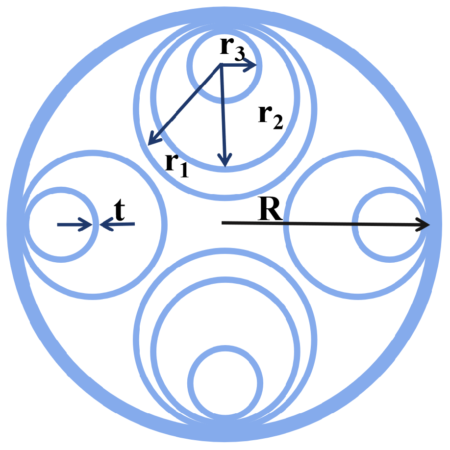
This work proposes a novel polarization-maintaining hollow-core anti-resonant fiber (PM-HC-ARF) structure, as illustrated in
Figure 1. The cross-sectional layout exhibits geometric symmetry, where each region comprises nested circular tubes, including either two or three concentric layers. The total cladding radius is denoted as
R, and all tube walls have uniform thickness
t. The radii of the innermost, middle, and outermost tubes are labeled as
,
, and
, respectively. The geometric ratios are defined as follows:
By appropriately tuning these structural parameters, strong optical confinement and high birefringence polarization modes can be simultaneously achieved.
The parameter ranges used in the fiber structure design are defined as follows: the cladding radius
R is within the range of
, and the tube wall thickness
t lies between
. The geometric ratio
is set within
, while the inner radius ratios
and
are both constrained to the interval
. The fiber structure proposed in this work adopts a three-tube configuration. Based on current advanced fabrication techniques, double-tube hollow-core fibers have already been fabricated [
26], and triple-tube fibers have also been fabricated [
27]. Therefore, the proposed structure is considered to have high fabrication feasibility under existing manufacturing conditions.
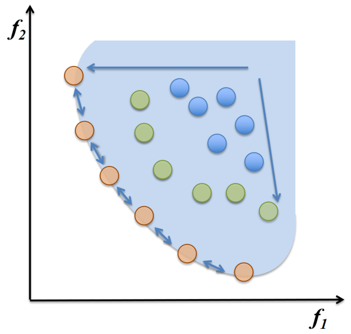
Figure 2 illustrates the Pareto front formed by the set of non-dominated optimal solutions shown as orange dots, while green and blue points represent candidate solutions in the current population. The arrows indicate the evolutionary trend of the optimization algorithm toward the Pareto-optimal region.
The proposed structure was analyzed using the finite element method (FEM) to simulate modal distributions and performance characteristics. By leveraging a Pareto-front-based multi-objective optimization algorithm, the complex interplay among design parameters was comprsolid-core fibersehensively explored, revealing their effects on fiber performance. The resulting optimized structure achieves high birefringence on the order of together with low confinement loss at the 1.55 m telecom wavelength, confirming the feasibility and effectiveness of the proposed design methodology.
4. Numerical Experiments
Based on the optimization results obtained from the Pareto search algorithm, a total of 12 non-dominated solutions forming the Pareto front were identified within 300 structural evaluations, as shown in
Figure 3. These solutions illustrate the trade off relationship between BI and CL. The BI values of the Pareto-optimal solutions range from
to
, while the corresponding CL values span from
dB/m to 12.99 dB/m. The results clearly reveal a positive correlation between BI and CL, indicating that achieving higher birefringence generally incurs greater confinement loss. This trend stems from the inherent physical contradiction between the asymmetry required to enhance polarization separation and the symmetry preferred for leakage suppression.
Importantly, within the BI range of to , several design points are observed to maintain confinement loss below 1 dB/m while still achieving moderate-to-high birefringence levels. Such solutions demonstrate strong potential for applications that require a balance between polarization-maintaining capability and low-loss transmission, such as coherent fiber-optic systems, polarization-sensitive sensors, and narrow-linewidth laser delivery.
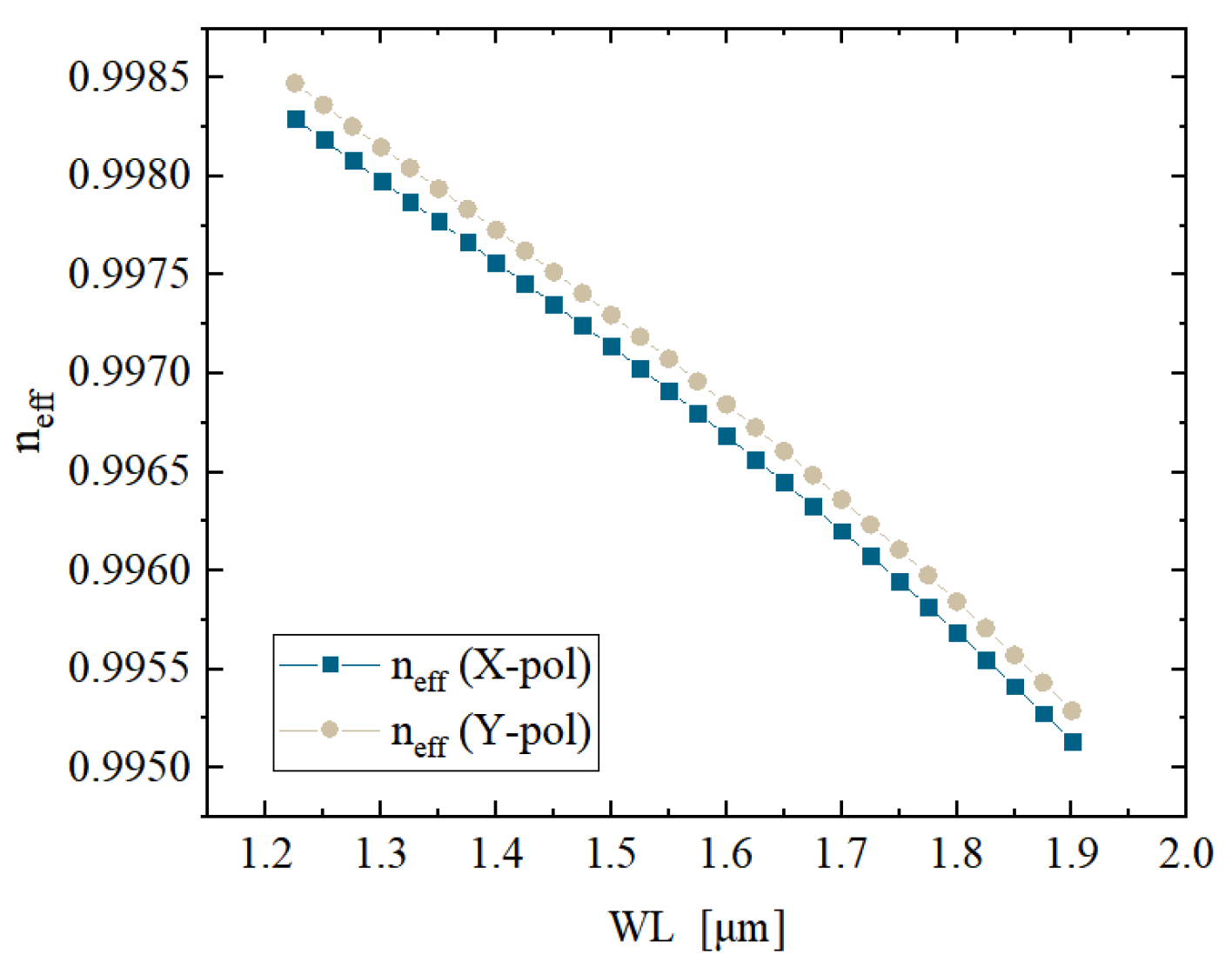
Under the optimal structural parameters (
,
,
,
, and
), the designed HC-ARF demonstrates desirable optical performance across the wavelength range of 1.225
m to 1.9
m, as illustrated in
Figure 4. The variation in effective refractive indices for the X and Y polarized modes as functions of wavelength. Throughout the entire band, a clear separation between the two polarization modes is observed, with both curves exhibiting a monotonically decreasing trend as the wavelength increases. At the operating wavelength of 1.55
m, the difference between the effective indices of X and Y polarizations reaches approximately
, indicating a prominent phase birefringence. This confirms the structural robustness of the design in maintaining polarization states, which is essential for polarization-sensitive applications.
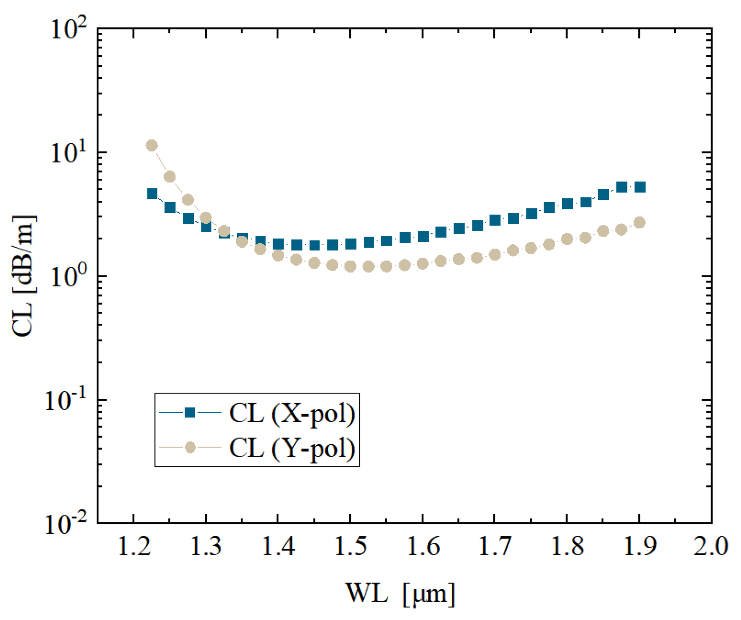
Figure 5 shows the wavelength-dependent variation in CL for the two polarization states. In the mid-band range of 1.4
m to 1.6
m, the confinement loss remains at a relatively low level. Specifically, for the Xpolarized mode, the minimum CL reaches approximately 1.58 dB/m at the wavelength of 1.55
m. This result confirms that the designed geometry achieves effective optical confinement within the target band, particularly under the anti-resonant condition, which plays a key role in minimizing leakage for both polarization modes.
Figure 6 further presents the variation in birefringence across the operational wavelength range for the proposed structure. The phase birefringence
remains stable within the range of
to
throughout the full spectral sweep, demonstrating excellent wavelength robustness, while the group birefringence
exhibits a similarly smooth variation, staying between
and
. In particular, both
and
show minimal fluctuation within the critical band from 1.2
m to 1.9
m, which is highly favorable for broadband polarization-maintaining applications. The inset of
Figure 6 shows the transverse mode profiles of the X and Y polarized fundamental modes at the wavelength of 1.55
m. A clear spatial separation between the two polarization states is evident, highlighting the distinct field localization patterns and confirming the structure’s strong polarization mode decoupling capability. This spatial anisotropy plays a crucial role in maintaining high birefringence and stable polarization guidance.
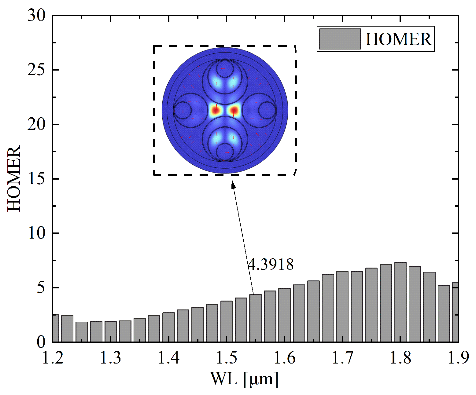
Figure 7 presents the wavelength scanning results of HOMER for optimal parameter 1. It can be observed that HOMER maintains values above 4 across the investigated spectral range from 1.2
m to 1.9
m, with a clear increasing trend toward longer wavelengths. At the telecom wavelength of 1.55
m, HOMER reaches a value of 4.39, which indicates a well-confined polarization state and strong modal discrimination. The gradual growth of HOMER with wavelength further confirms that the optimized asymmetric wall thickness structure provides enhanced robustness against polarization crosstalk in the longer wavelength region. The inset shows the electric field distribution of the higher-order mode at 1.55
m, illustrating effective separation from the fundamental mode and verifying the capability of the design to suppress higher-order mode resonance.
Based on the optimal parameter configuration (
,
,
,
, and
), the optical performance of the designed anti-resonant hollow-core fiber was evaluated over the wavelength range of 1.35–1.875
m.
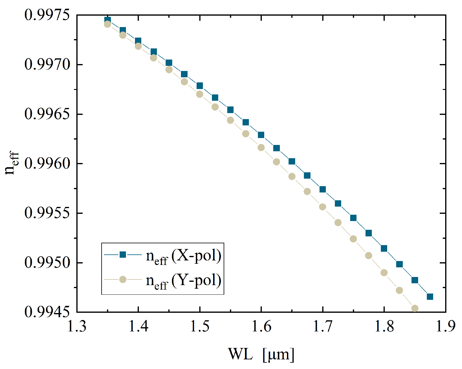
Figure 8 presents the variation in the effective refractive indices for the X and Y polarized fundamental modes as functions of wavelength. A stable offset is maintained between the two curves across the entire spectral range, indicating strong polarization distinguishability and consistent birefringence characteristics. This behavior suggests that the structure effectively supports dual polarization operation while preserving high modal contrast, which is essential for polarization-maintaining fiber applications.
Figure 9 illustrates the CL behavior of the fiber across different wavelengths. In the range of 1.35–1.6
m, the CL remains at a relatively low level for both polarization directions. Notably, the minimum CL reaches 0.9269 dB/m at 1.55
m, indicating that the structure provides excellent transmission performance within the target telecom band. As the wavelength increases beyond 1.6
m, a significant rise in confinement loss is observed, suggesting that the anti-resonant guiding condition becomes less effective at longer wavelengths. This trend highlights the importance of carefully tuning the structural parameters to optimize performance in the intended operating range.
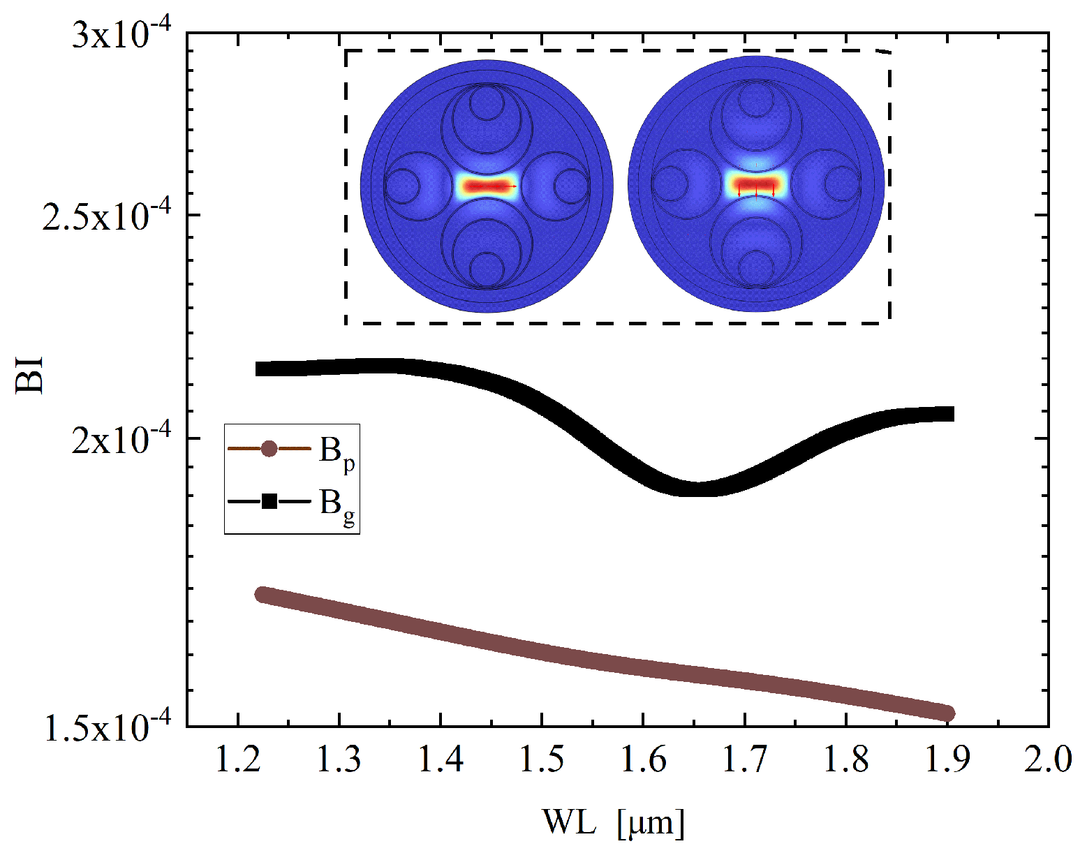
Figure 10 shows the wavelength dependent variation in birefringence. It can be observed that the phase birefringence
remains within the order of
to
and shows a clear increasing trend with wavelength, while the group birefringence
stays nearly constant on the order of
with only minor fluctuations. This complementary behavior indicates that the proposed structure simultaneously achieves a steadily growing
and a stable
, thereby ensuring robust polarization discrimination over the entire spectral range. The figure also includes inset mode profiles depicting the transverse electric field distributions of the fundamental modes for both polarization directions at 1.55
m. A clear distinction between the X and Y polarized modes confirms strong spatial mode separation and effective structural decoupling, which are critical for robust polarization-maintaining performance.
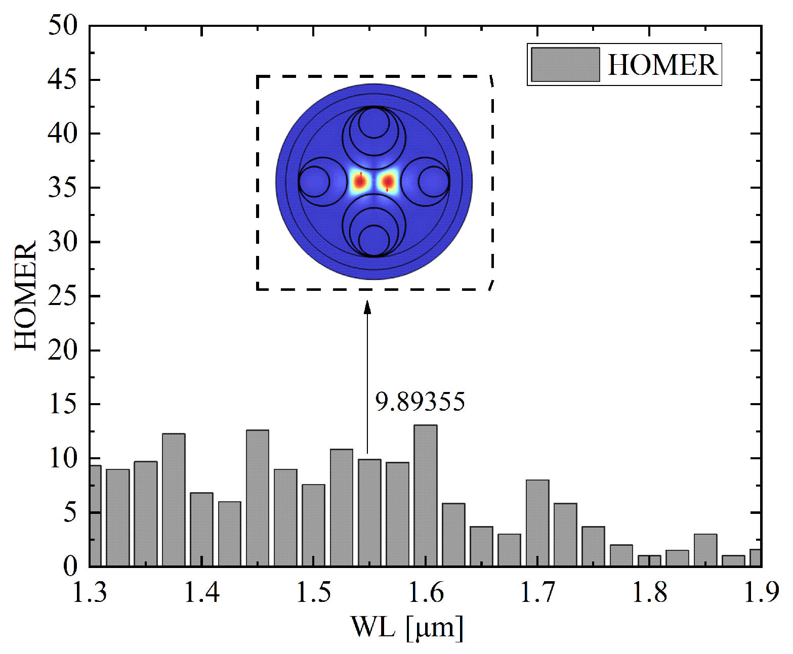
Figure 11 shows the wavelength scanning results of HOMER for optimal parameter 2. In this configuration, HOMER exhibits significant fluctuations across the scanned spectral range from 1.3
m to 1.9
m. The values vary between approximately 2 and 40, with pronounced peaks observed around 1.45
m and 1.55–1.60
m. At the telecom wavelength of 1.55
m, HOMER reaches 9.89, indicating enhanced modal discrimination at this operating point. Compared with parameter 1, the distribution reveals a more irregular spectral dependence, which suggests stronger sensitivity of higher-order mode resonance to wavelength detuning. The inset provides the electric field distribution of the higher-order mode at 1.55
m, confirming effective spatial separation from the fundamental mode and the ability of the structure to suppress mode coupling under the optimal parameter 2 configuration.
5. Disscussion
In the previous design, equal wall thicknesses were adopted for all capillaries in order to reduce fabrication complexity. To further explore the performance limits of the structure under asymmetric conditions, in this section we introduce differentiated wall thicknesses by assigning to the two horizontal capillaries and to the three vertical capillaries, while keeping the other parameters unchanged. The structure was re-optimized under this new configuration, and two representative optimal solutions are selected for detailed discussion. Parameter 1 corresponds to , , , , , and , yielding a confinement loss of 0.3367 dB/m and a birefringence of at 1.55 m. Parameter 2 is characterized by , , , , , and , resulting in a confinement loss of 0.1544 dB/m and a birefringence of at 1.55 m.
As illustrated in
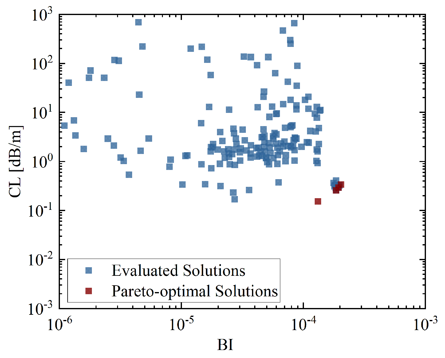
Figure 12, the introduction of the asymmetric wall thickness configuration significantly modifies the trade-off relationship between BI and CL. Compared with the equal wall thickness design presented in
Figure 3, the Pareto front is clearly shifted toward the lower-left region, indicating a simultaneous improvement in both birefringence and loss performance. In particular, within the region of
, the confinement loss is effectively suppressed to 0.1–0.3 dB/m. This represents nearly an order-of-magnitude reduction relative to the previous design at comparable BI levels, highlighting the advantage of breaking the wall thickness symmetry.
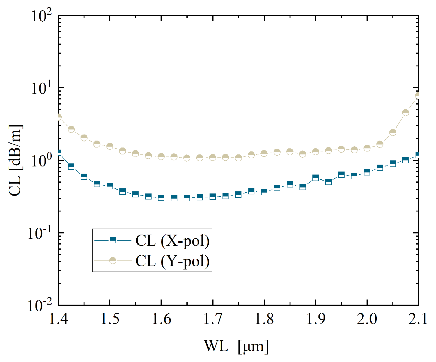
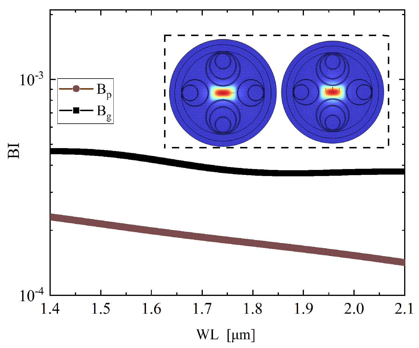
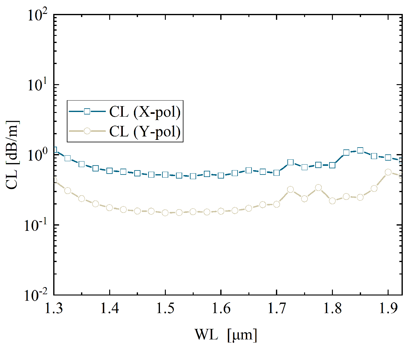
Figure 13 and
Figure 14 illustrate the broadband performance of the optimized asymmetric wall thickness structure. At the telecom wavelength of 1.55
m, the confinement loss of the low-loss polarization is evaluated to be 0.337 dB/m, accompanied by a phase birefringence
of
and a group birefringence
of approximately
. The confinement loss reaches its minimum within the range of 1.62–1.68
m, where values as low as 0.30–0.31 dB/m are achieved. Moreover, both
and
exhibit stable behavior across the 1.40–2.10
m window. Specifically,
gradually decreases from about
to
, while
remains nearly flat around the order of
. This complementary evolution demonstrates that the structure can simultaneously maintain sufficient phase birefringence and highly stable group birefringence, thereby ensuring robust polarization performance over a broad spectral region.
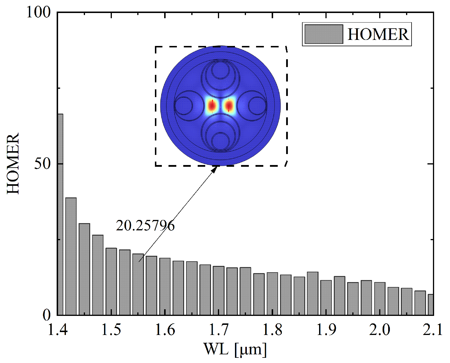
Figure 15 illustrates the wavelength scanning results of HOMER for the optimized asymmetric wall thickness structure with optimal parameter 1. It can be observed that HOMER remains relatively high across the spectral window from 1.4
m to 2.1
m, with values exceeding 15 throughout the entire range. At shorter wavelengths near 1.4
m, HOMER reaches its maximum above 70, indicating strong suppression of higher-order mode coupling. As the wavelength increases, HOMER gradually decreases yet stabilizes around 20 at 1.65
m, as highlighted in the inset, and maintains comparable values beyond 1.8
m. This behavior demonstrates that the optimized asymmetric wall thickness design provides robust higher-order mode extinction over a broad spectral window, thereby ensuring single-mode guidance and stable polarization maintenance across the near-infrared band.
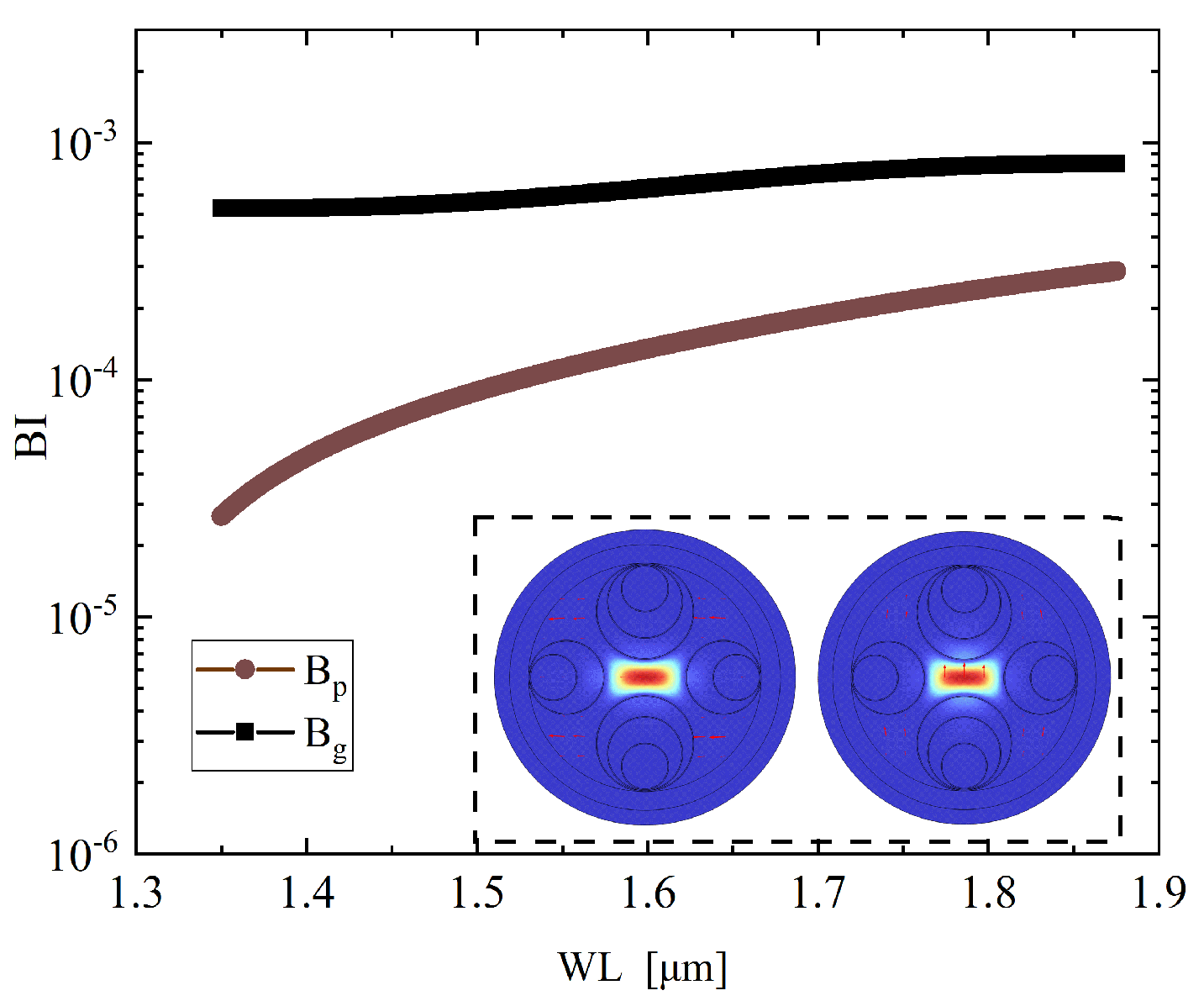
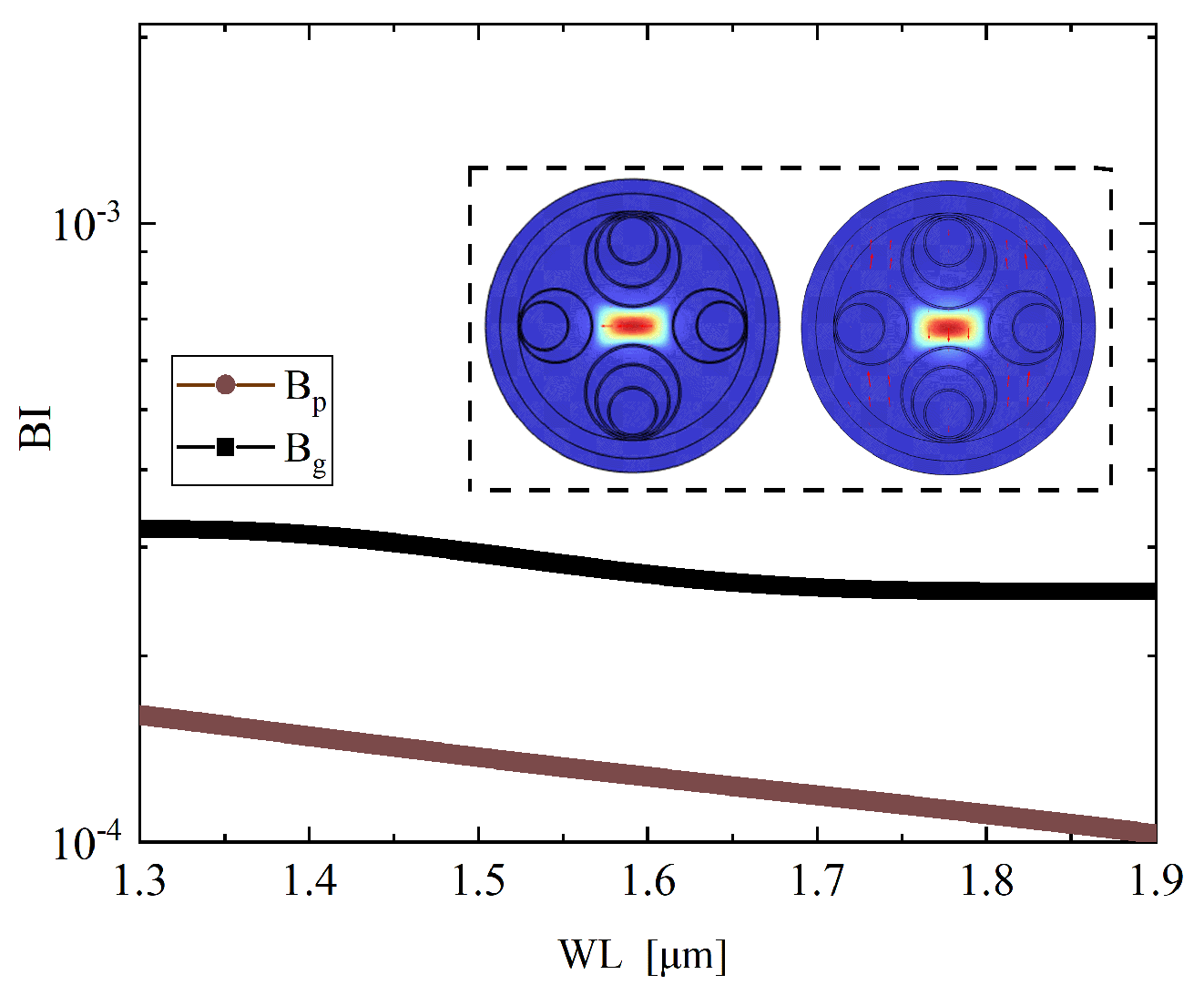
Figure 16 and
Figure 17 present the spectral characteristics of the optimized asymmetric wall thickness structure under the second optimal configuration. At 1.55
m, the confinement loss of the dominant polarization is reduced to 0.154 dB/m, accompanied by a phase birefringence
of
and a group birefringence
of approximately
. Across the 1.45–1.60
m window, the confinement loss remains consistently within 0.15–0.17 dB/m, demonstrating stable low-loss transmission over a broad wavelength range. Although the phase birefringence
gradually decreases from about
at 1.35
m to around
at 1.85
m, while the group birefringence
remains stable near the order of
with only minor fluctuations. This behavior indicates that, although
is slightly lower compared with Parameter Set 1, the configuration maintains sufficient phase birefringence together with highly robust group birefringence, thereby ensuring reliable polarization discrimination while achieving enhanced transmission efficiency.
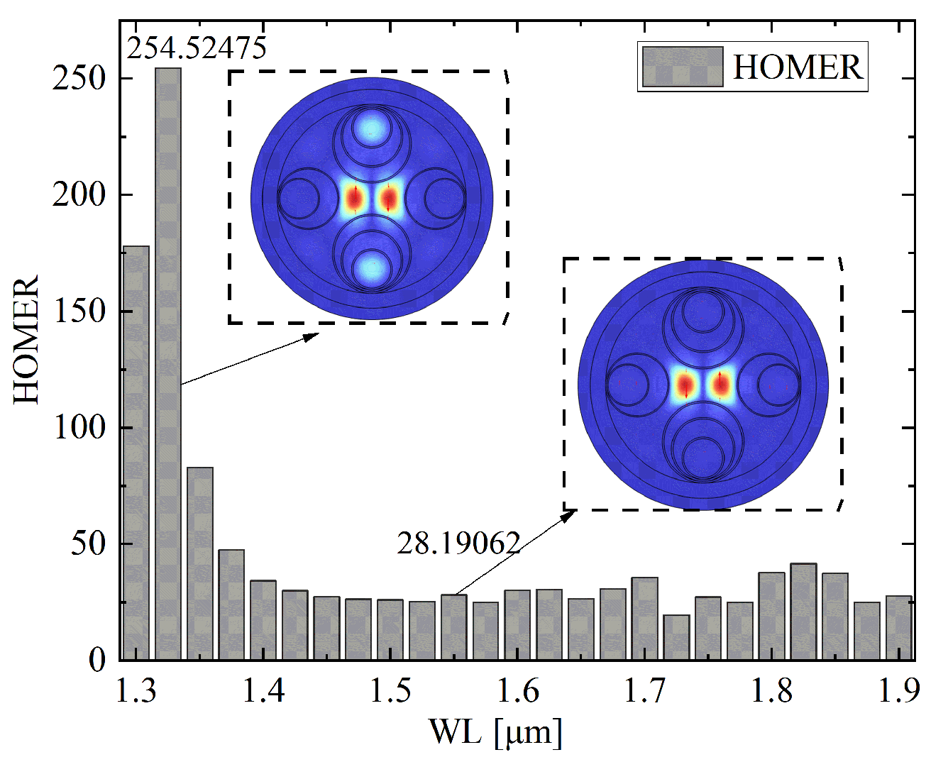
Figure 18 shows the wavelength scanning results of HOMER for the optimized asymmetric wall thickness structure with optimal parameter 2. It is evident that HOMER exhibits a pronounced peak at short wavelengths, reaching a maximum of 254.5 near 1.32
m, which indicates extremely strong suppression of higher-order mode coupling in this region. As the wavelength increases, HOMER decreases rapidly but remains well above 20 across the entire investigated range of 1.3–1.9
m. At 1.63
m, HOMER maintains a value of 28.2, as highlighted in the inset, confirming robust higher-order mode extinction in the telecom band. The overall trend demonstrates that, although HOMER decays with wavelength, the optimized structure under parameter 2 consistently ensures efficient suppression of higher-order modes, thereby supporting stable single-mode guidance over a broad spectral window.
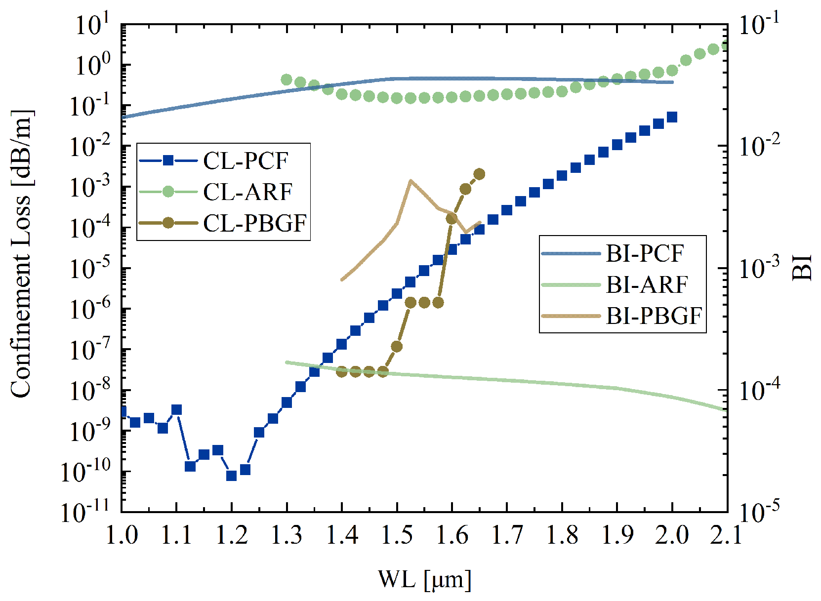
As shown in
Figure 19, the blue curve corresponds to the photonic crystal fiber [
28], the green curve represents the proposed anti-resonant hollow-core fiber with parameter 2, and the brown curve denotes the photonic bandgap fiber [
29]. The photonic crystal fiber achieves high birefringence on the order of
through strong geometric anisotropy, but its solid-core guidance introduces nonlinear effects, thermal sensitivity, and increasing confinement loss at longer wavelengths. The photonic bandgap fiber offers low loss near the bandgap center, yet its effective bandwidth is narrow and highly sensitive to structural tolerances, with birefringence typically in the range of
to
. In contrast, the proposed anti-resonant fiber maintains stable birefringence around
and nearly flat low loss across the 1–2
m band, while retaining the advantages of hollow-core guidance such as low nonlinearity and reduced thermal effects. This design thus provides a broader usable bandwidth and more robust polarization performance compared with the other fiber types.
Figure 20 presents the robustness analysis of the symmetric parameter 1 with equal wall thickness. As shown in the contour maps, the confinement loss remains below 2 dB/m within a reasonably broad region surrounding the optimal point, indicating strong tolerance to fabrication-induced deviations in both
A and
t. In contrast, the birefringence distribution exhibits greater sensitivity, with high values concentrated around a narrow ridge near
. Nevertheless, the birefringence stays above
within a practical tolerance window of
and
, which confirms that sufficient polarization-maintaining capability can still be achieved under typical fabrication errors.
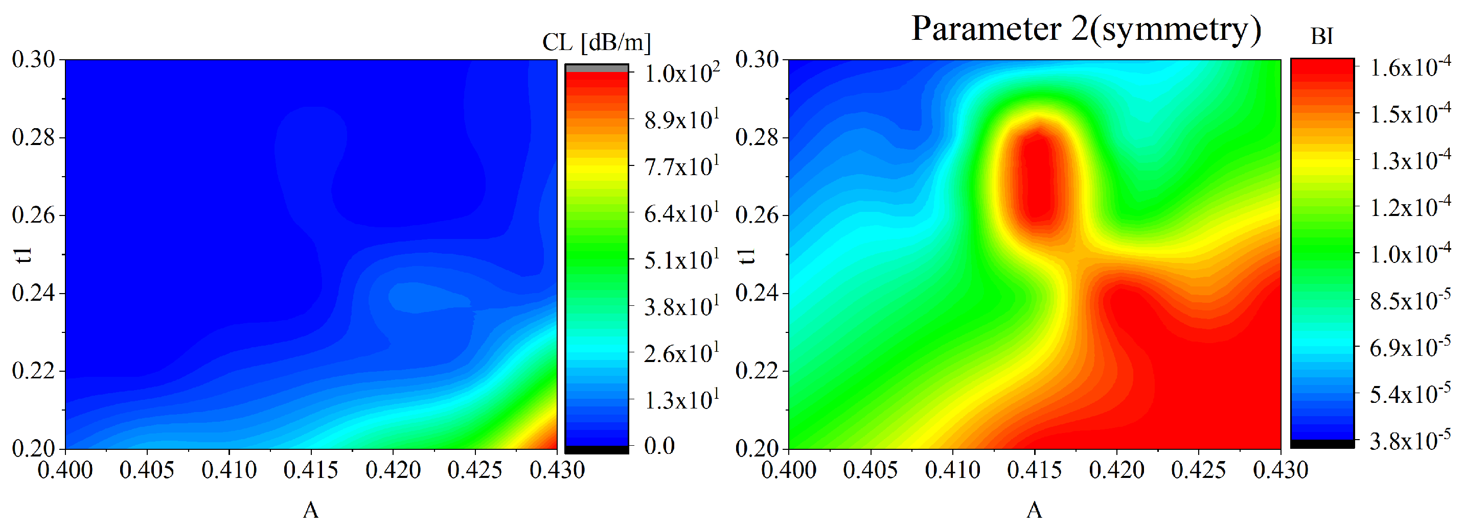
Figure 21 illustrates the robustness analysis of the symmetric parameter 2 with equal wall thickness. As shown in the contour maps, the confinement loss remains below 20 dB/m across a wide tolerance range, reflecting strong fabrication tolerance in terms of transmission performance. In contrast, the birefringence distribution reveals a pronounced peak around the optimal point, where BI exceeds
. Although the birefringence decreases gradually with deviations in
A or
t, values above
are maintained within a practical window of
and
, ensuring sufficient polarization-maintaining capability.
Figure 22 presents the robustness analysis of the asymmetric parameter 1. The contour plots indicate that the confinement loss remains below
dB/m across a broad tolerance window, confirming that the design maintains acceptable transmission performance even under fabrication-induced deviations. In terms of birefringence, the structure exhibits a stable high-BI region, with peak values close to
around the optimal point. While birefringence decreases gradually as
A,
, or
deviate, values above
are preserved within practical tolerances of
,
, and
.
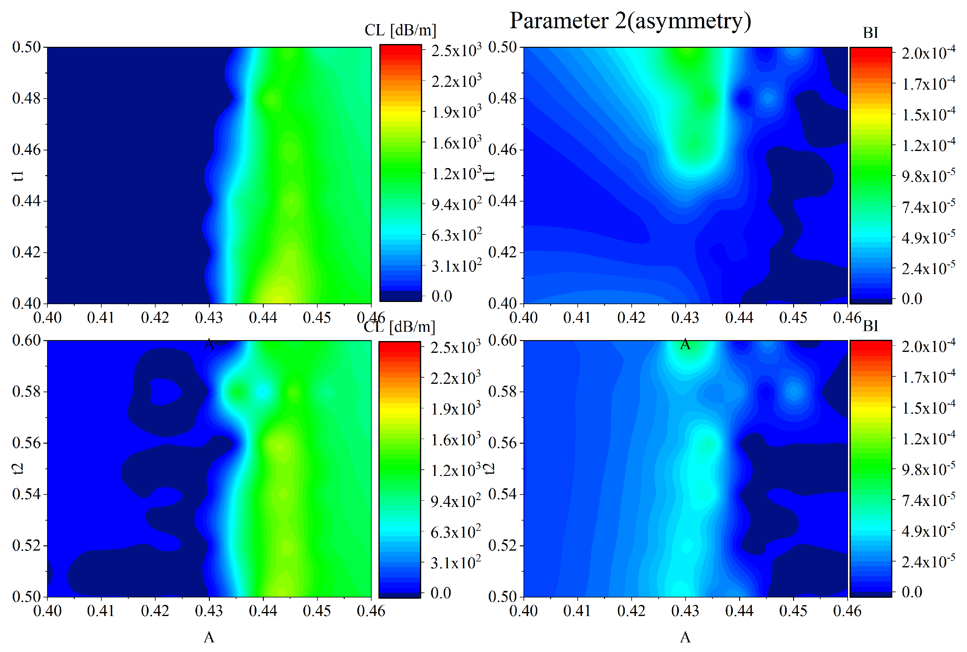
Figure 23 presents the robustness analysis of the asymmetric parameter 2. The contour distributions of confinement loss indicate that CL remains below
dB/m within a broad tolerance range, demonstrating acceptable robustness for transmission performance. On the birefringence side, a relatively stable region is observed around the optimal point, with maximum BI approaching
. Although the birefringence decreases with larger deviations in
A,
, or
, values above
are maintained within tolerances of
,
, and
. These results suggest that the asymmetric design of parameter 2 provides a balanced trade-off between low confinement loss and sufficient birefringence, ensuring stable polarization-maintaining performance even under fabrication imperfections.
Table 1 summarizes recent representative works on the optimization of HC-ARF structures. The comparison is conducted across five key dimensions: CL, BI, number of simulations performed, number of optimization objectives, and the optimization strategy adopted. It can be observed that most existing studies have primarily focused on single-objective optimization, with the common objective being the minimization of confinement loss [
21,
22,
30], while largely overlooking birefringence performance. Although some works [
21,
31] have preliminarily introduced dual-objective frameworks, they essentially rely on the weighted-sum approach to convert the problem into a single-objective formulation. Note that the asterisk * in the table indicates that the corresponding metric was not explicitly reported in the original reference.
Moreover, existing approaches often depend on large-scale simulation datasets sometimes exceeding 400,000 evaluations for neural network training or structure classification. In contrast, the present work achieves an effective performance trade off between confinement loss and birefringence using only 300 finite-element simulations. The proposed method yields Pareto optimal solutions with a minimum loss of 1 dB/m and birefringence up to , demonstrating the efficacy of the optimization.
This advancement is attributed to the adoption of a genuine multi-objective optimization strategy, which explores the design space more efficiently under limited computational resources. The algorithm achieves a balanced consideration of optical performance, computational cost, and engineering feasibility. In summary, compared with existing literature, the proposed multi-objective optimization framework enables simultaneous optimization of CL and BI at significantly lower computational cost, highlighting its practical potential for efficient HC-ARF design.
