1. Introduction
Laser wireless power transmission (LWPT) employs laser beams as energy carriers and utilizes photovoltaic arrays for optical-to-electrical energy conversion, offering several compelling advantages such as long transmission distance, low energy loss, high conversion efficiency, and compact system design [
1,
2,
3,
4,
5,
6]. LWPT has the potential to facilitate a highly flexible energy supply, providing a solution that breaks through the traditional energy limitations for unmanned aerial vehicles on long missions, unmanned submarines, robots, and other mobile devices [
7,
8,
9,
10,
11,
12]. However, current LWPT systems exhibit low photoelectric conversion efficiency, partly due to the mismatch between the photovoltaic receiver design and the characteristics of the laser beam, as well as the non-uniformity of laser irradiation [
13]. Traditional photovoltaic panels consist of multiple small laser cells [
14], and their design is based on a scenario of uniform solar irradiation, where all cells operate under equal light intensity to achieve efficient series or parallel output. The use of a typical Gaussian laser beam, characterized by strong central intensity and weaker edges [
15,
16,
17], leads to significant imbalances in current and voltage output across different areas of the photovoltaic panel. The central cells generate high output, whereas edge cells display inefficient loads due to lower light intensity, consuming circuit energy and causing local overheating, which may even pose safety risks [
18,
19]. Research has shown that the more uneven the distribution of light intensity, the more significant the power loss of low-efficiency cells in the overall system, markedly reducing system conversion efficiency. Therefore, optimizing receiver structure or introducing beam-splitting technology to balance light intensity is key to improving transmission efficiency [
20,
21,
22,
23,
24,
25].
In response to the issue of uneven laser irradiation, scholars have proposed a variety of innovative solutions and continue to advance technological iterations. One type of approach uses optical components to homogenize the laser beam [
26,
27]. For instance, in 2011, Stankevičius et al. proposed fundamental beam-mode shaping (FBS) technology to convert a circular Gaussian beam into a rectangular flat-topped intensity distribution. Experimental results demonstrated that the FBS component coupled 95% of the laser energy into the main beam with a nearly ideal rectangular profile, achieving an intensity uniformity deviation below 2.5% within the focal plane. However, this method is constrained by processing accuracy and cost, limiting its widespread application [
28]. To overcome the above limitations and address the specific requirements of far-field illumination for PA-LiDAR, Shuo Zhang et al. proposed the use of pyramid prism beam shaping (PPBS) technology to convert a Gaussian laser beam into a rectangular uniform spot in 2024. This technique can achieve an intensity uniformity ratio (K value) greater than 0.89 within the illumination region, high coupling efficiency, and excellent far-field transmission characteristics. However, its large-scale production applications are still constrained by processing accuracy and the complexity of system alignment [
29]. Another type of approach aims to enhance the uniformity of light intensity on the receiving surface by means of optical methods. For instance, in 2004, Ortabasi et al. first designed a closed spherical photovoltaic receiver termed a “powersphere”, which traps light within the cavity, preventing escape and allowing multiple reflections to achieve a theoretically uniform light distribution. In practice, however, the limitations of material absorption losses and powersphere size result in lower than expected output power [
30]. To overcome this limitation, Tiefeng He et al. developed a large-sized powersphere with a 1000 mm diameter in 2021, reducing output current differences between photovoltaic cells at various locations and increasing input power to 3000 W [
31]. Nevertheless, due to the absorptive nature of photovoltaic materials, regions of the inner wall under direct illumination experience much higher irradiance than reflection-dominated areas, and this heterogeneity in optical field distribution prevents the overall uniformity index from reaching its theoretical maximum. In 2024, Tiefeng He et al. proposed using a beam splitter to divide the incident laser into multiple beams of equal power, substantially expanding the direct illumination area and reducing irradiance non-uniformity. However, this method is limited by the performance of the beam-splitting components and assembly precision, meaning that although it improves light uniformity, it leads to a slight reduction in output power [
32]. To further address these limitations, Tiefeng He et al. proposed a dual-beam incident powersphere system based on cavity ellipsoidal reflection later in 2024. This system leverages ellipsoid surface reflection and symmetric dual-end incidence to expand the direct illumination area and improve the uniformity of light distribution on the receiving surface. Although uniformity was improved by this system, further enhancement remains possible [
33].
Overall, although existing light uniformity methods have achieved certain progress in terms of improving uniformity, they still face challenges such as low output power, complex component processing, and the insufficient optimization of the light field distribution. To further improve output power in wireless energy transfer systems, this study proposes an optimized powersphere light uniformity method that combines distributed incidence with an in-cavity reflector, using multiple laser beams with distributed incidence to adjust the power ratio of each beam and optimize the density distribution on the powersphere’s inner surface while maintaining a constant total input power. Simultaneously, a spherical mirror is positioned at the powersphere’s center to redirect light beams at multiple angles, illuminating areas otherwise unreachable by direct light. This study establishes a transmission model using LightTools (64) 8.6.0 (Synopsys, Inc., Optical Solutions Group; Sunnyvale, CA, USA) software to simulate and compare light intensity distribution between systems with and without a mirror. An experimental platform is also constructed for validation through practical testing.
2. Materials and Methods
To demonstrate the effect of laser distributed incidence combined with a spherical reflector in improving the light uniformity on the inner surface of a powersphere, we conducted a theoretical analysis as follows. Assume that the radius of the circle is r and the center is the origin O(0, 0). Let point Q(m, n) be a point on the circle defined by
. Owing to the symmetry of the circle, the analysis considers only the left half-plane. According to the geometric properties of the circle, the normal at point Q(m, n) passes through the center, so the equation of the normal at Q is
The expression obtained is
Assume that the light source is located at point A(x
1, 0) on the optical axis and point B(x
2, y
2) is the point symmetric to A(x
1, 0) about the normal. The coordinates of B can be calculated using the following formula for the symmetry of a point about a line:
The simplification yields
When light is incident from A to Q, according to the law of reflection in geometric optics, the reflected ray satisfies the condition that the angle of incidence equals the angle of reflection. At this time, the reflected ray is a straight line from Q to B. The equation of the line through points Q(m, n) and B(x2, y2) is
Substituting the expressions for x
2, y
2 from Equation (4) and simplifying algebraically, we obtain
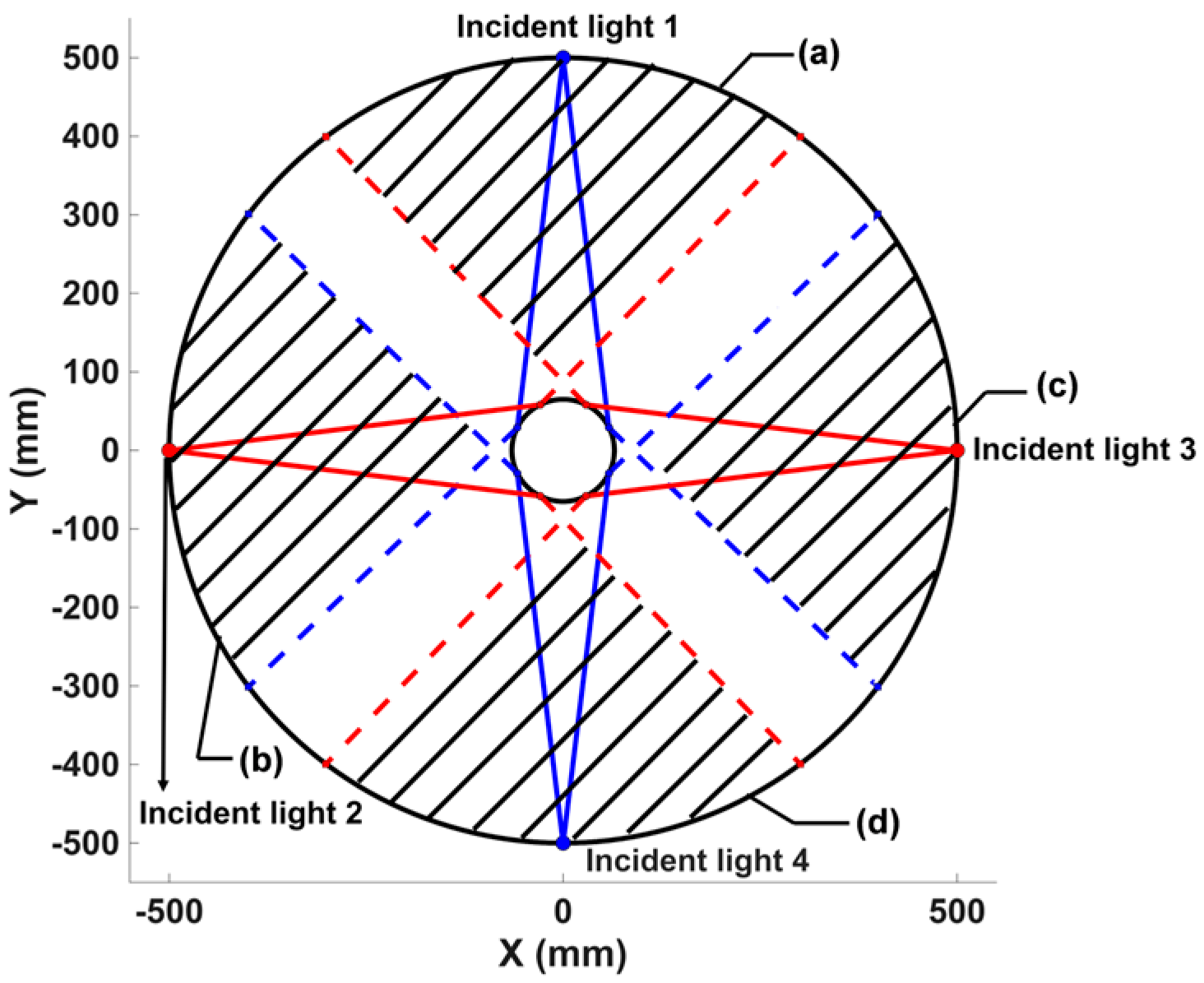
Equation (6) represents the final mathematical model of the reflected ray. Based on this model, the reflection of light from a circular sphere reflector under four-laser incidence was simulated using MATLAB R2025a (The MathWorks, Inc.; Natick, MA, USA), as illustrated in
Figure 1. It can be observed that the edge portions of Incident light 2 and Incident light 3 (red solid line), after reflection, are located on the opposite hemispherical side relative to their respective incident directions(red dashed line). Therefore, the edge regions of these symmetrical rays overlap, which increases the weak light intensity at the edges. In contrast, the central region of Incident light 1 and Incident light 4 has higher light intensity, and their reflected rays return to the vicinity of the incident aperture, overlapping with light in the superimposed regions. This forms the shaded regions (a) and (d) in
Figure 1 (The area enclosed by the red dashed line.), near Incident light 1 and Incident light 4. Similarly, the edge regions of Incident lights 1 and 4 (blue soled line) along with the central regions of Incident lights 2 and 3 create two other shaded regions (b) and (c) (The area enclosed by the blue dashed line). The total light intensity in each shaded region is the sum of two portions of weak edge intensity and one portion of higher central intensity, resulting in greater uniformity than with a single incident beam. Calculations show that the shaded regions generated by the four incident laser beams cover approximately 58.6% of the inner surface area of the powersphere. Increasing the number of incident laser beams allows the area of superimposed light intensities to cover the entire inner surface, which further reduces the light intensity difference within the powersphere and thus improves light uniformity.
3. Results
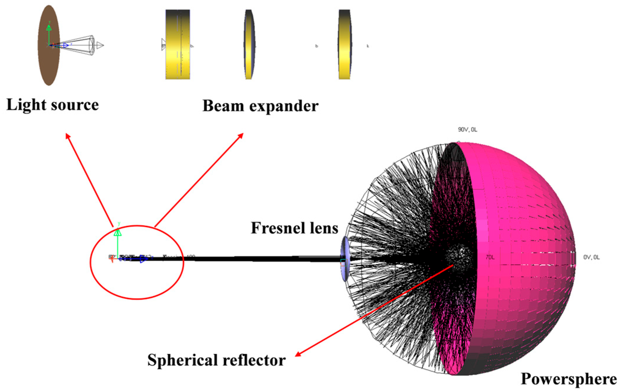
To investigate the effect of distributed incident lasers and beam splitting in a spherical reflector cavity on the output power of the powersphere, the light intensity distribution inside the powersphere cavity was analyzed under single-, dual-, four-, and six-laser incidence conditions, with and without a central reflector sphere. Simulations were conducted using LightTools software. As shown in
Figure 2, the light source was a semiconductor laser, with a divergence angle of 25°, a spot radius of 200 μm, and a wavelength of 808 nm. The total emission power was maintained at 30 W by adjusting the power of each laser according to the number of sources. The beam expander collimation system comprised four elements, providing a magnification of 3, and was installed 10.067 mm from the laser source. A Fresnel lens with a focal length of 80 mm and a radius of 100 mm was positioned 1000 mm from the light source to focus the laser beams within the powersphere. A powersphere with a radius of 500 mm was placed 1500 mm from the laser source. The simulation results indicated that a reflective sphere with a radius of 65 mm yielded the optimal optical field uniformity, and thus a spherical mirror with 100% reflectivity and this radius was centrally installed inside the powersphere. The system configuration for single-laser incidence is illustrated in
Figure 2. For dual-laser incidence, an additional beam path was introduced on the side opposite the single-laser arrangement, symmetrically aligned with the original. This enabled simulation of the dual-beam wireless power transmission process. In LightTools, both single and dual laser beams were placed on the
z-axis. For four-laser incidence, each additional laser was positioned along the
x-axis in both positive and negative directions based on the dual-laser, forming a cross-symmetrical arrangement in the X–Z plane and generating four symmetrical incident beams. Expanding to six lasers, one beam was further added along the
y-axis in both the positive and negative directions. As a result, the six light sources were located on the x-, y-, and z-axes, with one each in the positive and negative directions.
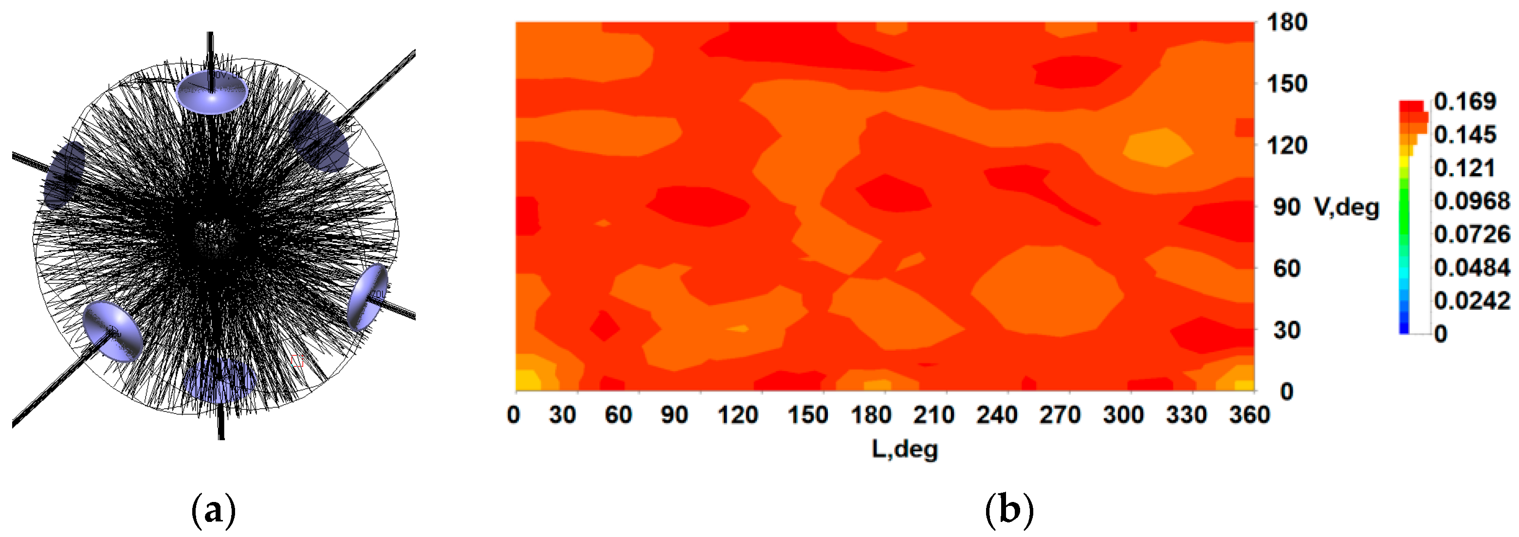
Based on the constructed wireless energy transmission model, the simulation results for six-laser incidence with a central spherical reflector were analyzed.
Figure 3a displays the ray tracing diagram, in which it is observed that the presence of the beam-splitting structure modifies the propagation paths of the rays, with the six symmetrically incident beams redistributed upon reflection by the spherical mirror. Weaker edge intensities overlap both with each other and with the central high-intensity regions of the opposing beams. This superposition effectively reduces the difference in light intensity. After the superposition of light, areas that initially have lower optical density receive increased illumination, meaning that the light intensity near the laser entry point becomes comparable to that in surrounding regions. This leads to a more uniform light distribution and reduces the variation in optical density across the inner surface.
Figure 3b shows the light intensity distribution within the powersphere. The V-axis represents the direction of a single laser beam incident from the left, with 0° indicating the midpoint on the opposite end during single-beam incidence, which serves to measure variation in the incident direction. The L-axis depicts the distribution law of light intensity varying with angle on the longitudinal plane orthogonal to the incident direction at the left side of the single laser. As shown in
Figure 3b, the light intensity distribution along the inner surface of the powersphere demonstrates high consistency, with a maximum light intensity of 0.169 W/sr and a minimum of 0.145 W/sr, giving a difference of 0.024 W/sr. Light field uniformity was evaluated using the extreme value ratio method, yielding a uniformity coefficient of 0.858. Moreover, the overall light intensity distribution is consistent with the optical path analysis in
Figure 1. Under six-beam incidence, the overlap area between edge-intensity regions and central high-intensity zones increases, producing a uniform intensity profile over the entire inner surface of the powersphere. This is consistent with both the ray trajectories in
Figure 3a and the uniform intensity distribution in
Figure 3b.
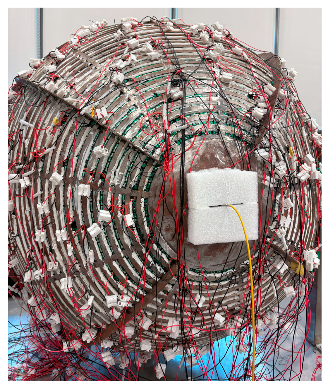
To verify the simulation results, an experimental platform was established, comprising a semiconductor laser, a beam-expanding collimation system, a Fresnel lens, a spherical reflector, and a powersphere. Owing to equipment constraints, the spherical reflector used in the experiment had a radius of 100 mm. The powersphere consisted of 7000 monocrystalline silicon photovoltaic cells, each measuring 20 mm × 20 mm, assembled into a sphere with a radius of 500 mm. The sphere could be disassembled into two hemispheres of equal volume. Beginning with the right hemisphere, every 100 cells were connected in series in sequence to form independent circuits, resulting in 70 circuits in total, with each hemisphere containing 35 circuits. Each circuit group could be measured independently for voltage and current. The experimental data were plotted as curve graphs to analyze the uniformity of light distribution on the inner surface of the powersphere. In practice, to avoid irreversible equipment damage from creating six openings, laser transmission was achieved by guiding the beam through an optical fiber to the exterior of the powersphere, with the fiber output port installed at the central gap in the photovoltaic array. This approach generated a focused spot effect similar to that of the Fresnel lens, avoiding energy loss introduced by optical elements, and ensured maximal laser energy utilization, as illustrated in
Figure 4.
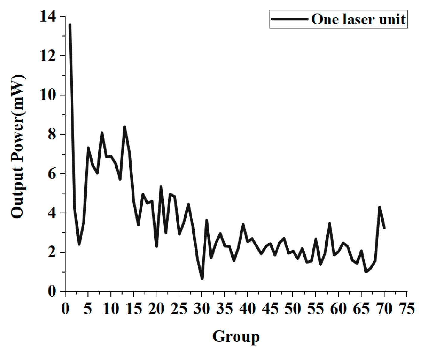
In the experiment, the current and voltage of all circuit groups were first measured under single-laser operation without the spherical reflector. The corresponding power of each circuit group was calculated and the data were fitted to distribution curves, as illustrated in
Figure 5. The horizontal axis in
Figure 5 represents the sequence number of the circuit groups and also reflects the light intensity distribution inside the powersphere, which is the V-axis in the intensity distribution diagram. The first circuit group corresponds to the 180° position on the V-axis. By observing
Figure 5, it can be found that the power of circuit group 1 was the highest, whereas the power of circuit group 3 dropped sharply to 2.408 mW. This decrease was attributed to manufacturing defects in the powersphere, which led to the power of some photovoltaic cells in circuit group 3 not being output normally. To avoid compromising circuit stability, these defective cells were disconnected during the experiment, leading to voltage and current values for group 3 that were lower than the actual light intensity. Overall, the power of groups 1 to 20 exhibited a gradual decline, indicating that the hemisphere with higher light intensity is on the same side as the laser entry point, which is contrary to the simulation results. The consistency of the experimental data was verified through multiple repeated measurements. Further analysis showed that in the experimental design, as both hemispheres of the powersphere had circular holes which could not be welded to photovoltaic panels, tin foil was used to cover these openings to maintain experimental rigor. Therefore, laser irradiation on the tin foil on the opposite hemisphere caused most of the light to be reflected back to the same hemisphere as the source, owing to the high reflectivity of tin foil. This resulted in higher light intensity at the laser entry area, with the distribution displaying a Gaussian pattern, meaning that the closer to the beam center the area is, the higher the intensity. Thus, as the V-axis angle decreased, power also decreased. The power distribution for circuit groups 20 to 70 remained stable, as these regions were not directly exposed to laser irradiation. Due to the differences in positions and the received laser irradiation intensity among the photovoltaic (PV) cell units inside the powersphere, there exist variations in the output current and voltage of each cell unit, thus leading to fluctuations in the overall output power. To mitigate the mismatch effect caused by non-uniform illumination among the cells, each cell can be connected to voltage regulation modules. By independently optimizing the power of each cell, the stability of the total system output can be achieved.
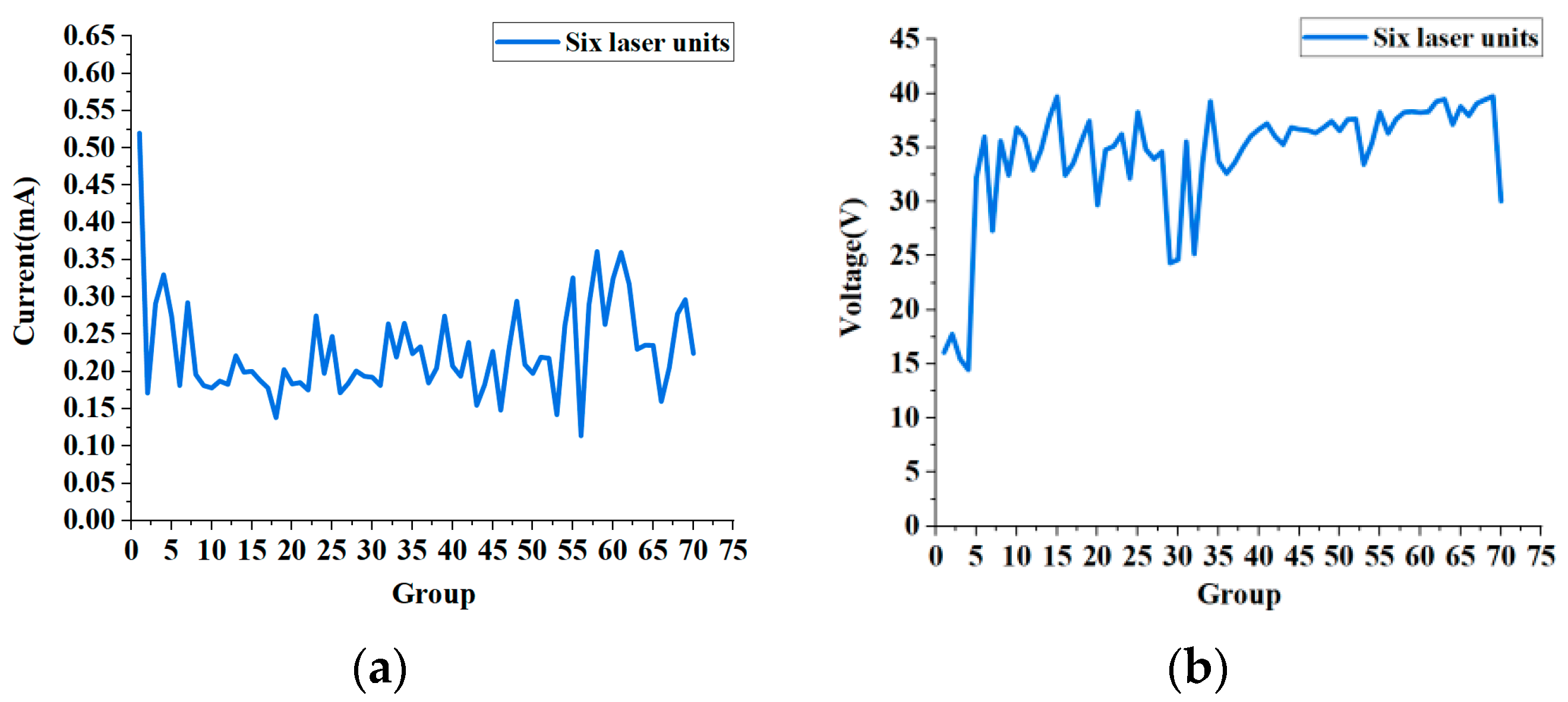
After ensuring the system’s stability, current and voltage values were measured for each circuit group under six-laser incidence with the reflective sphere in place. The resulting current and voltage data were fitted into distribution curves, as shown in
Figure 6a,b, respectively. As illustrated in
Figure 6, most current values ranged from 0.14 mA to 0.36 mA, with a maximum of 0.52 mA and a minimum of 0.11 mA, yielding a difference of 0.41 mA; meanwhile, the overall voltage values ranged from 14 V to 40 V, with a maximum of 39.74 V and a minimum of 14.47 V, resulting in a difference of 25.27 V.
4. Discussion
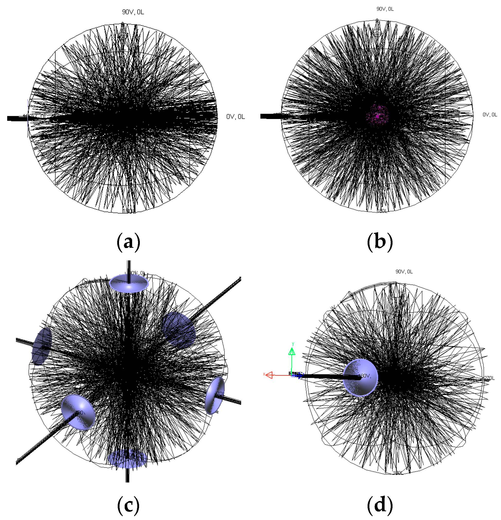
To more intuitively demonstrate the effect of distributed laser incidence combined with a spherical reflector in enhancing the uniformity of light on the inner surface of the powersphere, we compared ray tracing diagrams of single-laser incidence and distributed laser incidence, as shown in
Figure 7.
Figure 7a exhibits the propagation and distribution of light inside the powersphere when a single laser beam is incident and a spherical reflector is not present, demonstrating that after entering the powersphere, the laser exhibits a pronounced diffusive trend. Most of the light directly illuminates a vertical range of approximately 20° on the right side of the powersphere, forming a core band with high light density and intensity. In non-directly illuminated areas, particularly at vertical angles 70° to the left and right, the distribution of light is sparse and the light density is substantially reduced, indicating weak light intensity in these areas.
Figure 7b shows the internal light distribution in the powersphere with a spherical reflector under single-path incidence. Compared to
Figure 7a, the light is no longer concentrated in a specific region but is more evenly distributed throughout the powersphere. The light intensity in previously low-density areas is also enhanced.
Figure 7c exhibits the ray tracing diagram when six laser beams are incident without a spherical reflector. From this figure, it can be observed that the rays are primarily concentrated near the incident ports of the six lasers, as these beams are symmetrically arranged along each axis. Without a reflector to redistribute the light, the beams directly illuminate the area near the opposite laser inlet. As the distance from the inlet increases, the beams gradually become dispersed, and the light density in other areas inside the powersphere decreases significantly. Relative to
Figure 3a, the overall distribution of light remains uneven, with substantial variation in light density between regions.
Figure 7d presents the 3D ray tracing diagram for a single incident laser beam without a reflector. Comparison with
Figure 7c reveals that, for a single laser incidence, the directly illuminated area is confined to the powersphere in the positive direction along the
z-axis. In contrast, distributed incidence spatially allocates rays on the inner surface, covering the sphere from multiple angles and significantly increasing the area of direct irradiation. The ray tracing diagrams indicate that, compared to single-laser incidence, distributed laser incidence avoids an excessive concentration of light in any single region and achieves a broader distribution. The introduction of the spherical mirror further expands the area of direct irradiation, thereby improving the uniformity of light density on the inner surface of the powersphere.
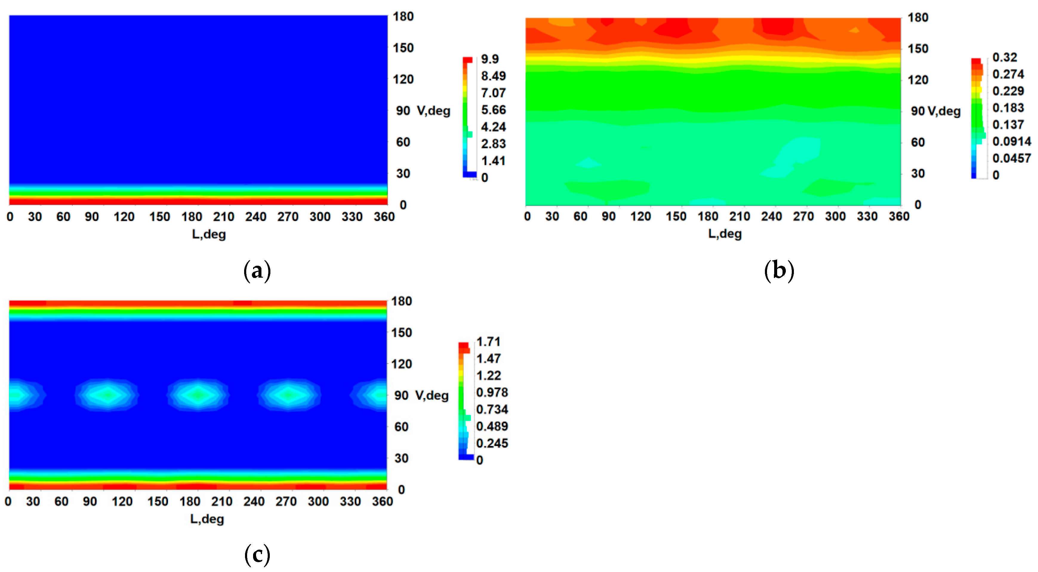
To gain a more comprehensive understanding of the energy distribution state, we analyzed the light intensity distribution on the inner surface of the powersphere.
Figure 8a displays the light intensity distribution under single-beam incidence without a spherical reflector, while
Figure 8b presents the light intensity distribution under single-beam incidence with a spherical reflector. In
Figure 8a, the inner surface in the V-axis range of 20–180° appears blue, indicating low light intensity in this area, primarily from reflected light, with the minimum intensity reaching 0 W/sr. Meanwhile, the V-axis range of 0–20° shows higher intensity due to direct laser irradiation, and the red area indicates that the maximum intensity reaches 9.9 W/sr. Overall, the maximum light intensity difference in
Figure 8a is 9.9 W/sr, with no significant variation across the L-axis. In
Figure 8b, the green region within the V-axis range of 0–135° expands significantly, and there are no blue regions with an intensity of zero. The light intensity ranges from 0.0914 W/sr to 0.229 W/sr, with much smaller intensity differences compared to the case without a spherical reflector. In the V-axis range of 135–180°, the light intensity gradually increases, reaching a maximum of 0.32 W/sr. The reflective sphere extends the high-intensity region from 0–8° to 150–180°, covering approximately one-sixth of the total surface area. Overall, the light intensity in non-directly illuminated regions improves, and the intensity difference is reduced.
Figure 8c shows the light intensity distribution inside the powersphere with six incident beams and no spherical reflector, demonstrating that the maximum-intensity regions along the y–z-axes are concentrated at the top and bottom, with a peak intensity of 1.71 W/sr. This results from direct illumination by two opposing lasers along the
z-axis, leading to significantly higher intensity in the V-axis ranges of 0–15° and 165–180°, presenting a symmetrical color distribution. Additionally, four circular regions with similar light intensity appear between 75° and 105° on the V-axis, with an intensity of approximately 0.489 W/sr. This situation arises from the symmetrical light source placement along the x- and y-axes, causing horizontal superposition of light in the central area, resulting in balanced intensity. Compared to
Figure 3b, the maximum intensity of 1.71 W/sr without the spherical reflector is nearly ten times that with the reflector in place, and the difference in maximum light intensity increases significantly. After analyzing and comparing the light intensity distribution inside the powersphere with and without a spherical reflector for single-beam or six-beam incidence, we find that distributed beam incidence substantially reduces light intensity differences within the powersphere cavity. The use of a spherical reflector further enhances overall intensity while reducing the intensity difference. The combination of these two approaches therefore significantly improves the uniformity of light intensity on the inner surface of the powersphere.
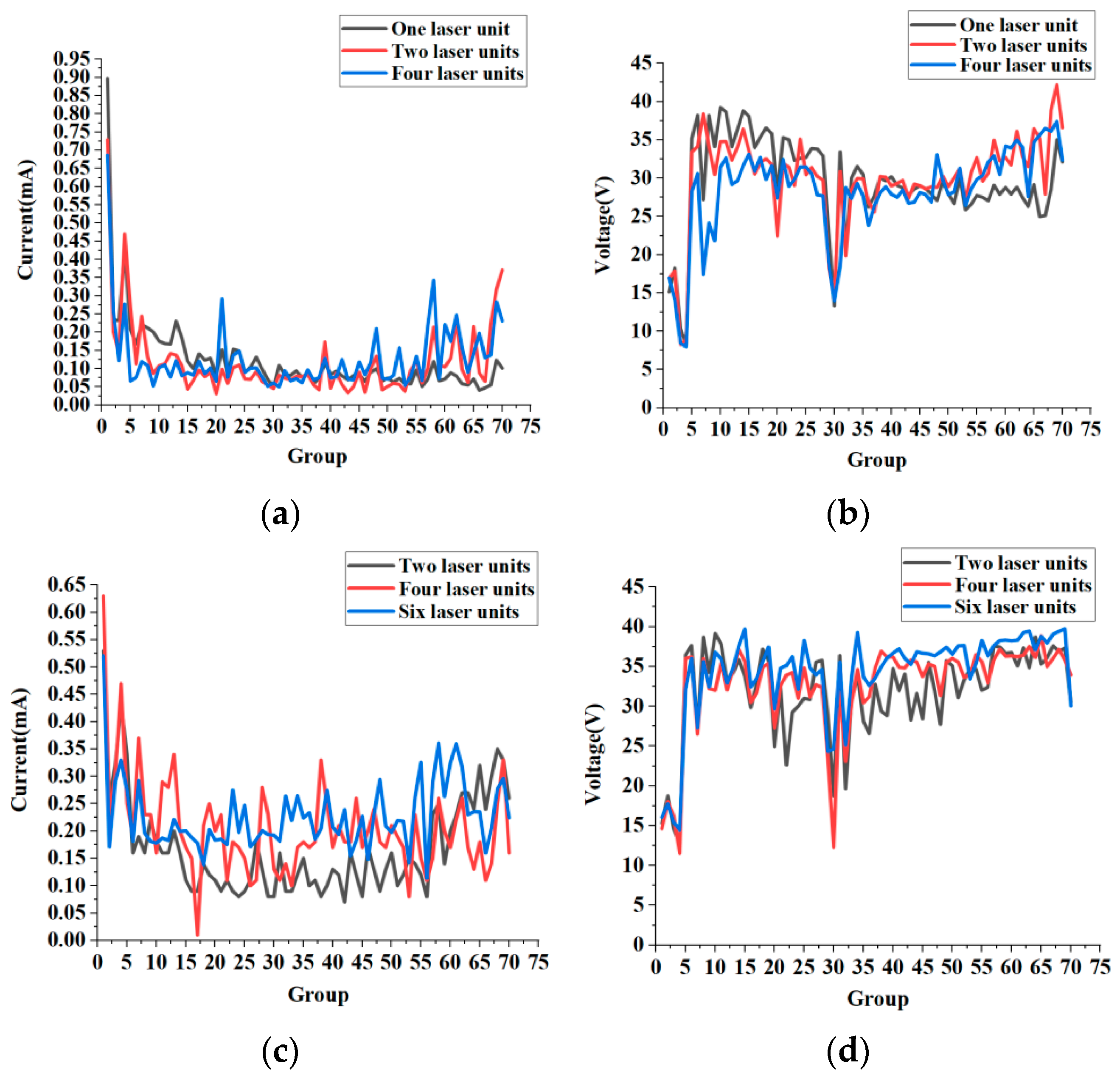
To verify the accuracy of the simulation results, the current and voltage for two and four lasers were first measured without the spherical reflector, and the measured data were fitted to curve graphs, as shown in
Figure 9a,b. Subsequently, with the spherical reflector in place, the current and voltage for two, four, and six lasers were measured, with the results presented in
Figure 9c,d.
Figure 9a presents a comparison of the current curves for the three groups of experiments. The overall current values range from 0.03 mA to 0.48 mA. The current for a single laser is generally lower and shows a gradual downward trend, with a maximum of 0.89 mA and a minimum of 0.04 mA, indicating a substantial difference. When two and four lasers are incident, curve fluctuations decrease; for two lasers, the maximum and minimum current values are 0.73 mA and 0.031 mA, respectively, while for four lasers, they are 0.69 mA and 0.052 mA. The difference between maximum and minimum currents also decreases significantly. Compared to the single laser, the overall current curve for two and four lasers shows an upward trend.
Figure 9b presents the voltage curves for these three experimental groups. The single-laser voltage curve exhibits considerable fluctuations, especially in groups 1 to 6, where the amplitude of voltage changes is large. In contrast, voltage curve fluctuations for the two- and four-laser groups are smaller, and the differences between voltage values are less than those observed with a single laser. As shown in
Figure 9c,d, the current and voltage distributions change significantly after adding a spherical reflector. Most current values range from 0.08 mA to 0.38 mA. Current values in non-directly illuminated regions increase, and the curves become smoother and show a clear upward trend. When six lasers are incident, differences in current values between groups further decrease, and the current remains higher than in the other groups, demonstrating the best overall uniformity. The voltage curve in
Figure 9d also demonstrates this effect. After the beam-splitting action of the reflective sphere, the minimum voltage increases from 8.01 V to 11.54 V, and the overall voltage in groups 20–70 is enhanced. When six lasers are incident, the difference between maximum and minimum voltages is the smallest among all groups. These results indicate that combining beam splitting inside the cavity using a spherical reflector with distributed laser incidence can effectively improve the uniformity of the light intensity distribution in the powersphere.
To further explore the effect of the spherical reflector and distributed lasers on the output power of the powersphere, 70 powersphere circuits were connected in parallel, and the overall output current and voltage were measured. The total output power of the powersphere, with and without the reflector, was then compared. As indicated in
Table 1 and
Table 2, the total output power increases steadily as the number of lasers increases, regardless of whether the spherical reflector is used. This increase is especially notable as the number of lasers increases from two to four. These results demonstrate that, with constant total laser emission power, increasing the number of lasers enhances system output power.
A comparison of
Table 1 and
Table 2 indicates that, when the spherical reflector is introduced into the powersphere, the total output current of both two- and four-laser systems increases significantly, and the total voltage also increases to a certain extent. Specifically, the total power for two lasers increases from 9.00 mW to 17.64 mW, representing a rise of approximately 96%, nearly doubling, while for four lasers, total power increases from 12.92 mW to 21.14 mW, a rise of 0.64 times. Analysis of each experimental group shows that when six lasers are used with the reflector, the power reaches its highest value among all experimental combinations, with an output power of 22.09 mW, approximately 2.52 times the corresponding value for a single laser without beam splitting. These data indicate that, compared to the powersphere system without a reflector, the system with a reflector achieves higher output power.
During the experiment, the main errors originate from alignment, adjustment, and positioning errors, especially the alignment relationship between the incident optical axis and the spherical reflector. Experiments have shown that even if the deviation distance of the optical axis from the axis of spherical reflector is one-quarter of the spot diameter, the loss rate is only 4.7% of the total power [
33]. Thus, the impact of errors on the experimental results is within the acceptable range. Furthermore, digital multimeters were used for both voltage and current measurements, with a voltage accuracy of 0.5% and a current accuracy of 1.5%. This allows for the evaluation of the impact of experimental measurement errors on the experimental data. Given that there are over 70 sets of experimental data, the relevant errors were not labeled one by one in the graphs.
5. Conclusions
Owing to the light-absorbing properties of photovoltaic materials, there is a significant difference in light intensity between the directly irradiated and reflected regions on the inner surface of the powersphere, making ideal uniformity challenging to achieve. To address this problem, this study investigates light uniformity technology for the laser wireless energy transmission system based on a powersphere receiver and proposes a method combining multiple incident lasers with a spherical reflector positioned at the center of the powersphere. The use of a spherical reflector to direct beams into regions that are not directly illuminated, combined with distributed incident lasers, optimizes the beam density across the inner surface of the powersphere and improves light uniformity.
This article presents a theoretical analysis and verification of the feasibility of optimizing light intensity distribution in the powersphere using distributed laser incidence. A simulation model of a laser wireless power transmission system was developed with optical software to simulate the light equalization effect of a reflector and distributed laser incidence. An experimental platform was subsequently established to validate the simulation results. The findings demonstrate that increasing the number of lasers, while maintaining a constant total output power, effectively improves illumination uniformity within the powersphere. When a spherical reflector is not used to split the beam, the total output powers for one, two, and four lasers are 8.75 mW, 9.00 mW, and 12.92 mW, respectively, displaying a gradual upward trend as the number of lasers increases. The experiments also confirm that introducing a reflector further enhances the output power of the powersphere. Specifically, with two lasers, the total input power rises from 9.00 mW to 17.64 mW, and with four lasers, it increases from 12.92 mW to 21.14 mW. When six lasers are incident and a spherical mirror is introduced, the total output power reaches a maximum of 22.09 mW. These results indicate that the combination of distributed laser incidence and the installation of a spherical reflector can effectively improve light intensity distribution within the powersphere cavity and increase the output power of the laser wireless power transfer system. Based on research into the relationship between the number of lasers and power, it is possible to further explore optimization strategies for the coordinated operation of multiple lasers, providing valuable insights for the broader application of wireless energy transfer technology.
