Due to the requirement that the size of the lighting system designed is larger than the diameter of the LED chip, a single LED chip can be approximated as a point light source, and the radiation intensity of a single LED point light source can be obtained:
where
is the angle between the light ray and the axial ray of the LED,
represents the radiant intensity of a single LED chip at any angle, and
stands for the axial radiant intensity of the LED. Since the emission characteristics of the LED chip can be approximated to a Lambertian source,
m is approximately 1. Therefore, the radiant intensity of the entire LED chip can be expressed as:
When transitioning from the spherical coordinate system (Equation (2)) to the Cartesian coordinate system (with the LED chip positioned at the origin), the radial distance
d (between the LED and freeform surface points in spherical coordinates) is redefined as
S (Euclidean distance in Cartesian coordinates,
, where
are the LED coordinates). Substituting
d = S and
(since
is the angle between the light ray and the LED’s axial ray,
) into Equation (2) yields Equation (3):
2.1. Total Internal Reflection (TIR) Freeform Surface Design
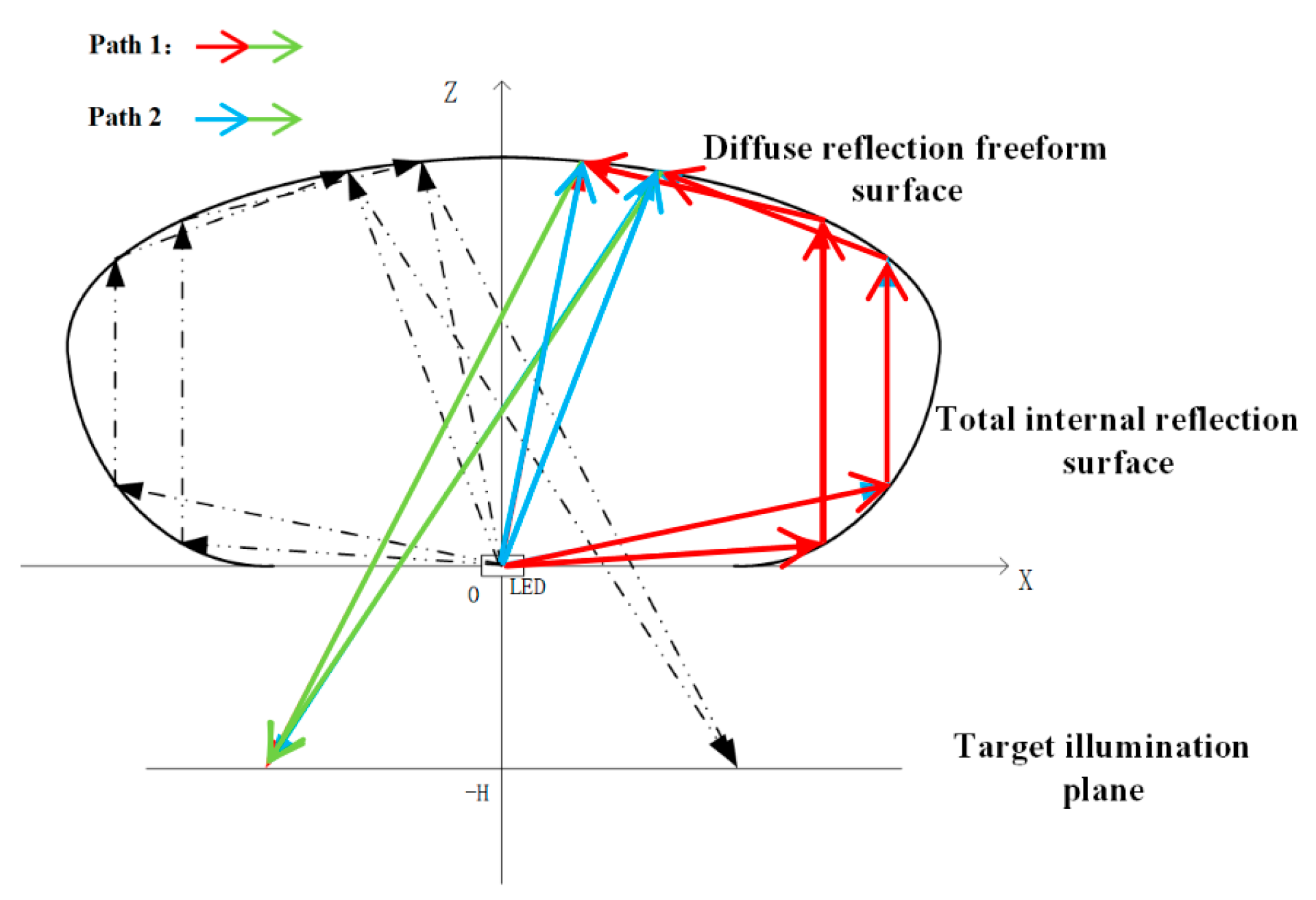
Firstly, a coordinate system is established as shown in
Figure 3, with the central axis of the TIR lens designated as the z-axis and the position of the light source set as the coordinate origin [
17]. Assuming the LED light source is an ideal point source, light rays emanate directly from the origin and are incident on point
of rotationally symmetric TIR surface. After undergoing total internal reflection, the rays emerge as light rays parallel to the z-axis.
Define the angle between the light emitted by the LED source and the x-axis as
(must be consistent with the TIR surface’s collimation constraint), and the maximum incident angle as
. Divide
evenly into
N parts, such that
. For TIR, the reflection direction of light satisfies the law of reflection (angle of incidence = angle of reflection) and the phase condition derived from Maxwell’s equations. The unit vector of incident light inside the lens is
(
: angle between incident ray and x-axis), and the reflected light (parallel to z-axis) has a unit vector of
. Based on the vector relationship between incident ray, reflected ray, and surface normal (
) for TIR:
where
k is a positive scaling factor (ensuring normal vector direction),
n is the lens refractive index,
is the incident light unit vector,
is the reflected light unit vector, and
is the TIR surface normal vector at point
. Substituting
and
into Equation (5), and normalizing the normal vector, we re-derive the correct expression for
(consistent with the physical meaning of TIR):
is a scaling coefficient for the x-component of the normal vector, defined as
, where
(scaling factor from Equation (5)). It quantifies the contribution of incident light’s horizontal component to the TIR surface normal direction. The incident light ray is collinear with the unit vector
from the origin to point
. Thus, it can be concluded that:
The line connecting adjacent points
and
is perpendicular to the normal at point
, that is:
Based on the above recursive relationship, starting from the initial point
, the coordinates of each point
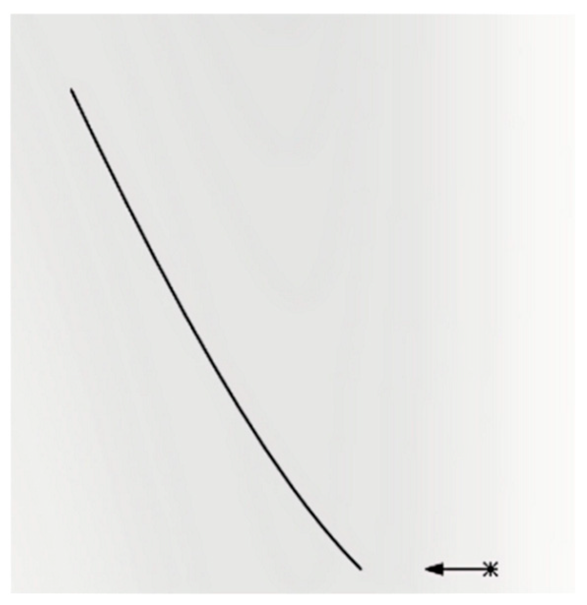
on the generatrix are calculated sequentially. Through iterative convergence, the complete contour of the generatrix of the total internal reflection freeform surface can be obtained. The 2-D contour plot of the designed total internal reflection freeform surface is shown in
Figure 4 (the TIR freeform surface has a radial range of 0–12 mm and an axial height of 5–8 mm, matching the composite lens’s compact design).
2.2. Diffuse Reflection Freeform Surface Design
The diffuse reflection structure is an off-axis freeform surface (symmetric about the z-axis in
Figure 2) with a 3D morphology synthesized from 2D contour curves. Its spatial range spans from the upper edge of the TIR freeform surface (point
in
Figure 3) to the outermost boundary of the lens, with a maximum radial width of 35 mm and a height variation of 8–12 mm (optimized to avoid light blockage between the TIR and diffuse surfaces). The surface is discretized into 2000+ discrete points with a spacing of 0.05 mm, ensuring smooth curvature transitions (curvature radius variation < 0.1 mm
−1) to prevent local light concentration.
As shown in
Figure 5,
denotes the irradiance of light reflected by the mirror surface,
represents the irradiance of light incident on the rotationally symmetric diffuse reflection surface, and
E is the total irradiance on the combined freeform surface, we can get:
Since the rotationally symmetric diffuse reflection surface is regarded as a series of continuously distributed second-order Lambertian light sources with rotational symmetry, this paper takes the irradiance distribution on the target plane in the X-Z 2-D coordinate system as an example [
18].
Figure 6 shows the point
P on the rotationally symmetric diffuse reflection surface and point
T on the target plane can be represented by coordinate points
and
on the 2-D plane. According to the knowledge of space vector, we can derive the following expression:
where
and
respectively represent the light vector emitted and absorbed from the rotationally symmetric diffuse reflection surface,
is the normal vector on the freeform surface,
is the angle between
and
.
In this work, the rotationally symmetric diffuse reflection surface is modeled as an ideal Lambertian surface. Consequently, light emanating from this surface exhibits a cosine (Lambertian) radiation profile, scattering uniformly in all directions within the hemisphere above the surface. This fundamental assumption leads to the following relationship:
where
is the maximum radiance in the direction normal to the rotationally symmetric diffuse reflection surface. Therefore, the irradiance distribution on the target illumination plane can be expressed as:
where
E is the irradiance received by the freeform surface (W/m
2), as given by Equation (4),
is the distance between the rotationally symmetric diffuse reflection surface and the target illumination plane; and
dA denotes the area element on the freeform surface.
as the general target-plane irradiance formula. The structure is defined as an ideal Lambertian reflector, meaning its bidirectional reflectance distribution function (BRDF) follows the cosine law. This ensures that light reflected from the surface is uniformly scattered within the upper hemisphere (relative to the local surface normal), with no directional dependence. The BRDF describes the reflectance properties of the freeform surface and is given by:
where
is the rotationally symmetric diffuse reflection surface reflectance, considering the practical scenario, the value of
is set to 0.85 in the calculations presented in this article. As shown in
Figure 6a, substituting Equations (10)–(13) reduces the irradiance simulation algorithm for point
) on the target plane, so we can get:
Equation (14) quantifies the irradiance on the target plane (at point
)) generated by light that reaches the diffuse reflective freeform surface via initial total internal reflection (TIR) and then undergoes diffuse reflection, where
as the specific target-plane irradiance at point T. Correspondingly, as illustrated in
Figure 6b, the irradiance distribution on the target illumination plane, generated by the secondary diffuse reflection event from this diffuse reflection surface acting as a Lambertian source, is derived as follows:
As shown in
Figure 6c, point
P on the rotationally symmetric diffuse reflection surface and point
T on the target plane can be further represented as points
and
) in the X-Z 2-D plane, respectively. This paper assumes that there are
N radiation points on the rotationally symmetric diffuse reflection surface, and each radiation point radiates to two non-adjacent points. Therefore, based on the above-described rotationally symmetric diffuse reflection surface, it can be further concluded that when the n-th diffuse reflection occurs, the illuminance distribution of the target illumination plane generated by the diffuse reflection freeform surface is:
The superscripts of coordinates (e.g., ): They represent the spatial coordinates of discrete points on the diffuse surface () and target plane corresponding to the u-th diffuse reflection. The u − 1 index indicates that these coordinates are updated iteratively based on the previous ((u − 1)-th) reflection, ensuring consistency with the cumulative effect of multiple reflections. the subscript of irradiance (e.g., ): denotes the target-plane irradiance generated by the u − th diffuse reflection on the diffuse surface.
According to the energy conservation constraint, the total radiant flux incident on the diffuse surface (from direct LED rays and TIR-reflected rays) must equal the flux scattered to the target plane (accounting for reflectance losses). Mathematically, this is expressed:
where
is the area of the diffuse surface,
E is the irradiance on the diffuse surface (Equation (9)),
is the target plane area, and
is the target irradiance (Equation (14)). This constraint ensures no net energy loss in the reflection process (excluding material absorption). The tangent and normal vectors at the junction between the diffuse surface and the TIR surface (point
) must be continuous to avoid light refraction losses at the interface. This is enforced by setting the 1st and 2nd derivatives of the diffuse surface’s 2-D contour (at the junction point) equal to those of the TIR surface’s generatrix (Equation (8)).
For each discrete point
on the initial contour, the irradiance E(
) (Equation (9)) and the corresponding target irradiance
(
) (Equation (14)) are calculated. The error between the simulated
and the desired uniform irradiance (
) is defined as:
where
N = 128 × 128 (target plane grid resolution). The contour points are adjusted iteratively using the 4th-order Runge–Kutta algorithm to minimize
. Each iteration updates the
z-coordinate of
based on the error gradient (
), with a step size of 0.01 mm to ensure convergence. The iteration stops when
< 3% (typically after 50–80 iterations), yielding the optimized 2-D contour (
Figure 7a). The optimized 2-D contour is rotated 360° around the z-axis (with 0.5° angular increments) to form the 3-D diffuse reflection surface (
Figure 7b).
The computationally designed 2-D contour profiles of the total internal reflection (TIR) freeform surface (derived as shown in
Figure 4) and the diffuse reflective freeform surface (derived as shown in
Figure 8a) were imported into SolidWorks
® (2022 SP3.0) for 3-D reconstruction. The 2D contour of the composite freeform surface (
Figure 8a) unifies the TIR and diffuse reflection surface profiles in the z-x plane, where the horizontal axis aligns with the x-axis of
Figure 4 (TIR design) and the vertical axis aligns with the z-axis of
Figure 3, ensuring consistency with the overall coordinate system. The resultant composite freeform lens geometry is presented in
Figure 8 (The composite freeform lens (TIR + diffuse) has a maximum radial width of 25 mm and a volume < 10 cm
3; the 2-D contour in
Figure 8a uses a coordinate scale where 1 unit = 1 mm):
Figure 8a displays the final 2-D contour profile of the integrated lens design, the 2D contour line of the composite freeform surface (in the z-x plane, with the horizontal axis representing the lateral direction (x-axis) and the vertical axis representing the axial direction (z-axis) of the lens). This contour integrates the TIR freeform surface generatrix (
Figure 4) and diffuse reflection freeform surface contour (
Figure 7a), serving as the blueprint for 3D reconstruction via rotational symmetry around the z-axis. And
Figure 8b shows the corresponding 3D solid model of the fabricated lens component.
