Article

Mathematical Analysis and Freeform Surface Modeling for LED Illumination Systems Incorporating Diffuse Reflection and Total Internal Reflection

1
School of Mechanical and Electronic Engineering, Gandong University, Fuzhou 344000, China
2
School of Electrical and Automation Engineering, East China Jiaotong University, Nanchang 330013, China
*
Author to whom correspondence should be addressed.
Photonics 2025, 12(10), 1025; https://doi.org/10.3390/photonics12101025
Submission received: 8 August 2025 / Revised: 29 September 2025 / Accepted: 10 October 2025 / Published: 16 October 2025
(This article belongs to the Special Issue New Perspectives in Micro-Nano Optical Design and Manufacturing)

Abstract

Indirect lighting systems employing light-emitting diodes (LEDs) and diffuse reflective surfaces are prevalent in applications demanding stringent illumination uniformity. However, conventional diffuse reflection approaches exhibit inherent limitations (inevitable light loss from multiple diffuse reflections and trade-off between uniformity and efficiency). To overcome these constraints, we introduce a novel composite freeform surface illumination system that synergistically integrates total internal reflection (TIR) with diffuse reflection. This design leverages the inherent Lambertian radiation characteristics of LEDs and the properties of ideal diffuse reflectors. A rigorous mathematical model is derived based on the luminous intensity distribution of the LED chip, the prescribed illumination requirements on the target plane, the principle of energy conservation, and Snell’s law. The resulting system of nonlinear equations is solved to generate a series of two-dimensional profile curves, which are subsequently synthesized into an off-axis freeform surface. Simulated results demonstrate that the proposed system achieves higher optical efficiency and superior illumination uniformity compared to traditional diffuse reflector configurations. This universal and feasible methodology broadens the application potential of high-performance diffuse indirect lighting.

1. Introduction

As the fourth-generation lighting source, LEDs offer several advantages, including compact size, rapid response, long lifespan, high brightness, and low thermal output [1,2,3,4,5]. Therefore, they have not only transformed people’s perception of general lighting design and application but also provided key solutions to address the needs for energy conservation and environmental protection in the present and future. In optical design, a freeform surface is strictly defined as a non-symmetric surface (without rotational or translational symmetry) whose sag (surface profile) cannot be completely described by simple mathematical functions such as conic sections, spherical equations, or rotational symmetric polynomials. This distinguishes it from rotationally symmetric surfaces (e.g., spherical, paraboloidal) and simplified symmetric surfaces, whose profiles rely on symmetric geometric constraints. Due to the approximately Lambertian cosine distribution of the spatial luminous intensity of LEDs, direct illumination without secondary light distribution can lead to light pollution and non-uniform illumination [6]. Therefore, in the practical application of LED lighting, secondary light distribution design is essential for LEDs to ensure that their light energy distribution meets practical lighting requirements [7,8,9]. In recent years, researchers have focused on designing double freeform surface lenses to achieve uniform illumination on the target plane, but this approach is also accompanied by a series of issues such as overexposure and glare effects caused by direct and simple reflective structures. So the indirect lighting technology based on diffuse reflective freeform surfaces has emerged [10,11]. Diffuse reflection technology can also be used to enhance the illumination uniformity of lighting systems. B. Liu proposed an indirect illumination method, which is composed of planar LED array and diffuse reflection freeform surface, the simulation result shows that the irradiance uniformity of the detection area is above 90% [12]. CH Tsuei designed an LED lighting system for indoor lighting using diffuse reflectors. Their research not only improved the uniformity of the target illuminated surface but also suppressed glare effects to some extent [13]. So illumination uniformity can also be enhanced through diffuse reflection. However, the diffuse reflectors are less efficient than other optical designs in terms of light efficiency. Therefore, improving the efficiency of diffuse reflectors remains an important research focus. Zhu incorporated diffuse reflection into the design of lighting systems, establishing a system of nonlinear equations based on LED circular arrays and high diffuse reflection surfaces [14]. Solving this system of nonlinear equations via relevant algorithms yields both the coordinate data and contour of the diffuse reflection freeform surface. The required freeform surface shape is then obtained through rotational symmetry about the axis. Simulation experiments have demonstrated that, compared with traditional direct lighting, this design performs well in terms of irradiation uniformity and lighting efficiency. However, the theory underlying diffuse reflection still requires refinement. To address this, Zhu et al. implemented energy-saving measures, which significantly mitigated the low efficiency of the design. They established a mathematical simulation algorithm for the radiation of the illuminated plane using the bidirectional reflectance distribution function (BRDF) of the inner surface of the diffuse reflection freeform surface. Based on conservation laws, they calculated the expected values on the target plane and established a set of nonlinear algebraic equations. Compared with traditional design methods (direct illumination and hemispherical inner surface diffuse illumination), this method exhibits better uniformity and illumination efficiency [15]. Sun Xiang proposed an off-axis design method for diffuse reflective surface. Compared with conventional approaches, this method enables the generation of distinct asymmetric surfaces tailored to different LED arrays under far-field conditions, thereby achieving both enhanced efficiency and significantly improved uniformity [16].
This paper presents an LED lighting system (a compact optical unit integrating a single LED source and composite freeform surfaces, which is designed to achieve uniform illumination on the target plane) that integrates specular total internal reflection (TIR) and diffuse reflection freeform surfaces. A mathematical model for the irradiation distribution of the freeform surface is established, which is derived from the characteristics of a single LED Lambertian source and the properties of ideal diffuse reflection. Moreover, the desired illumination distribution over the target plane is specified. By incorporating the principles of energy conservation and spatial Snell’s law, and based on the collinearity condition of light propagation and the perpendicularity between adjacent point normals and line vectors, a coordinate recursive equation system is established. The generatrix profile of the rotationally symmetric TIR surface is derived via iterative fitting. And then a mathematical simulation algorithm is established to represent the radiation of the irradiated plane by using the bidirectional reflectance distribution function of the diffuse freeform surface. By solving the derived system of nonlinear algebraic equations, a series of 2-D contour curves are obtained and combine these 2-D curves are further synthesized into a diffuse reflection freeform surface. The results show that, in comparison with traditional diffuse reflectors, the proposed illumination system achieves significantly higher illumination efficiency and superior uniformity.

2. Materials and Methods

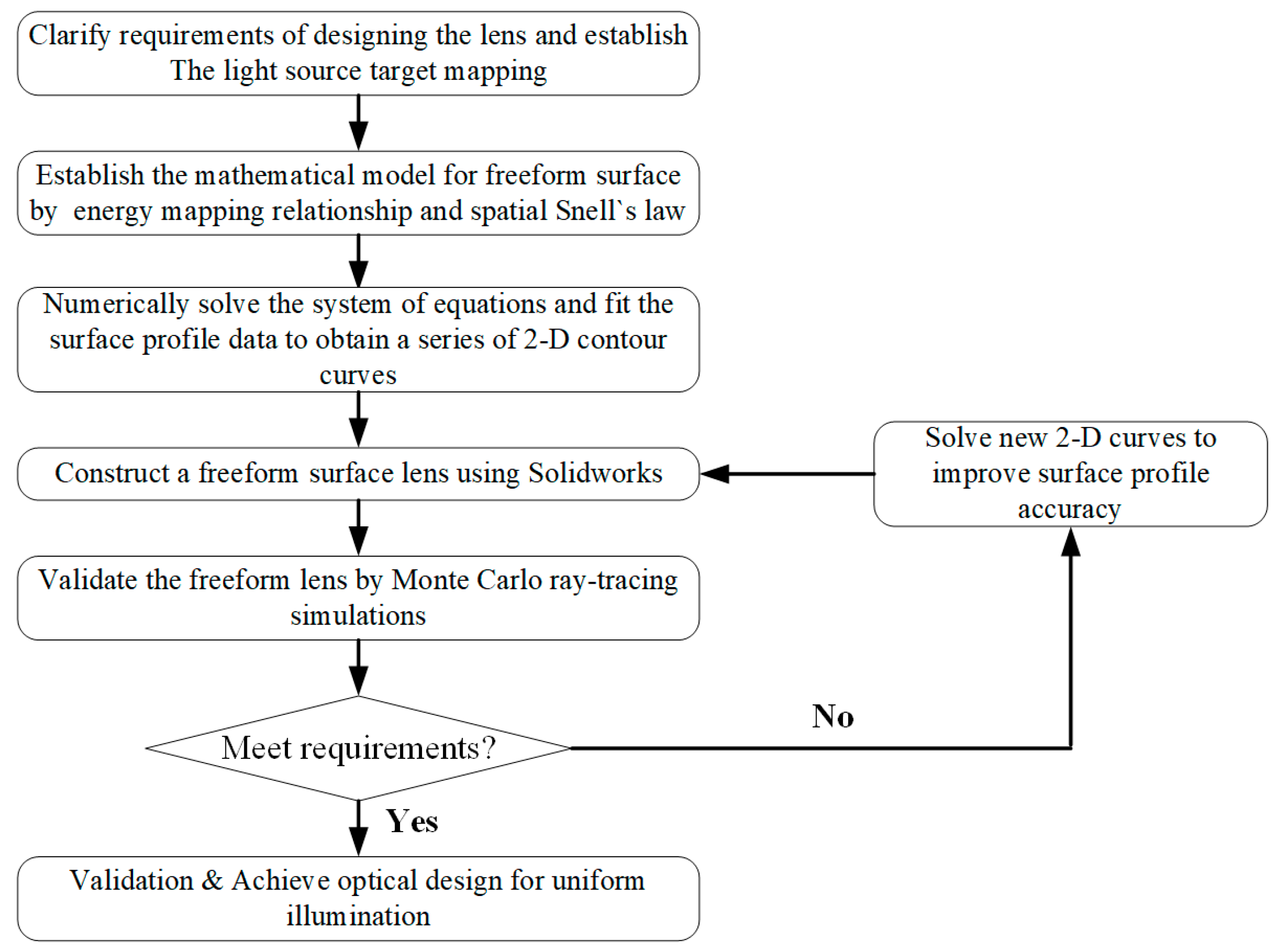
The design methodology flowchart is presented in Figure 1. In summary, we first conceptualized an LED illumination system incorporating a composite freeform surface that synergizes specular total internal reflection (TIR) with diffuse reflection. Subsequently, a freeform lens was computationally designed based on this concept. The optical performance of the designed lens was rigorously evaluated through Monte Carlo ray-tracing simulations. This design-evaluation process was iterated until the simulation results met the predefined illumination specifications, yielding an optimized freeform lens. The detailed steps of the design methodology are elaborated below.
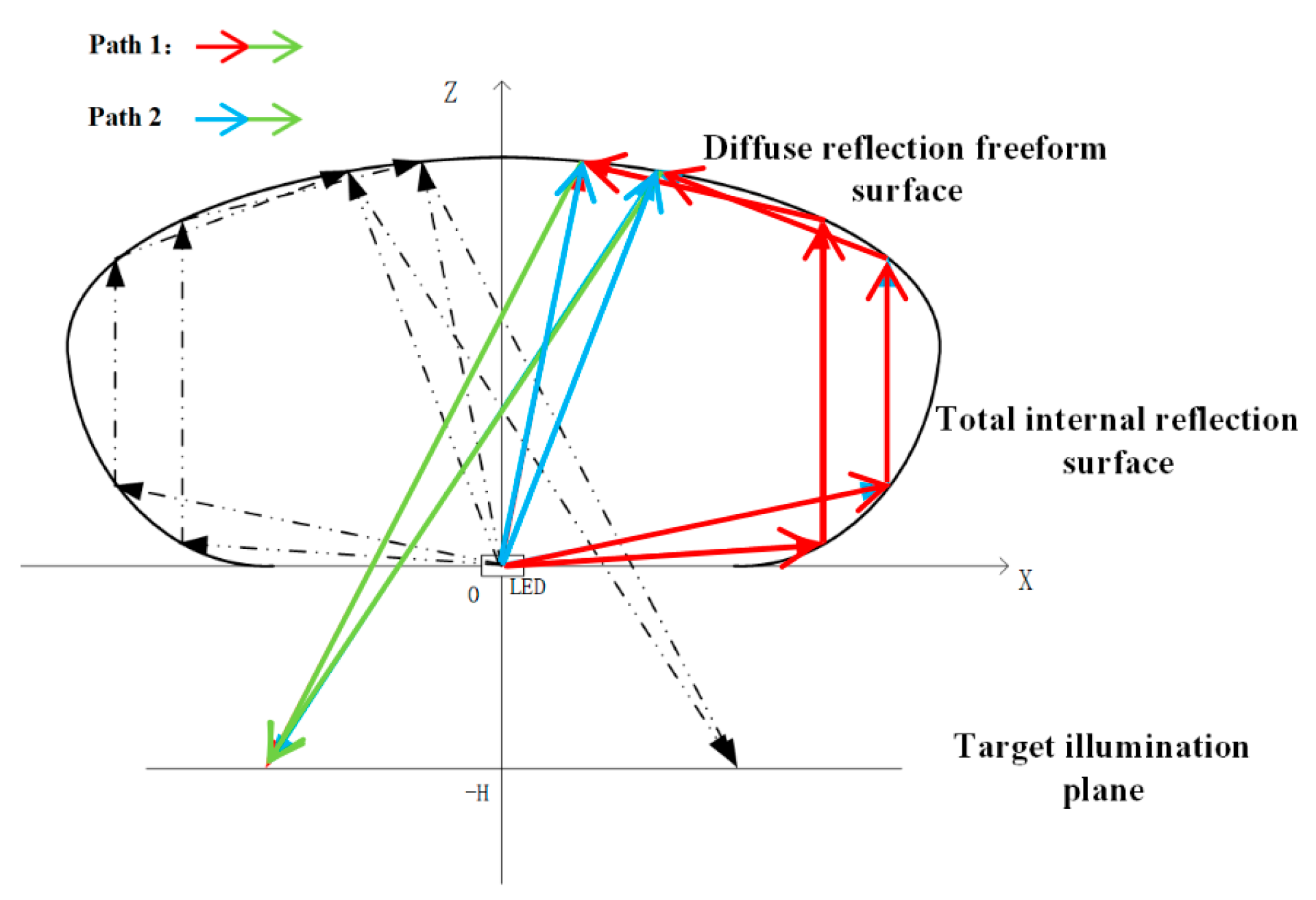
Figure 2 depicts the cross-sectional profile of the composite freeform surface illumination system developed in this study. Incident light from the LED source is partitioned into two distinct optical paths: (1) rays propagating towards the rotationally symmetric TIR surface undergo total internal reflection and are subsequently directed onto the diffuse reflective freeform surface; (2) rays incident directly upon the diffuse reflective freeform surface propagate towards the target plane. The combined illumination on the target plane arises from the superposition of the light reflected by the diffuse surface (originating from Light Path 1: LED → TIR freeform surface → diffuse reflective freeform surface → target illumination plane) and the light transmitted/reflected by the diffuse surface (originating from Light Path 2: LED → diffuse reflective freeform surface → target illumination plane).
Due to the requirement that the size of the lighting system designed is larger than the diameter of the LED chip, a single LED chip can be approximated as a point light source, and the radiation intensity of a single LED point light source can be obtained:
I e ( θ ) = I 0 cos m θ
where θ is the angle between the light ray and the axial ray of the LED, I e ( θ ) represents the radiant intensity of a single LED chip at any angle, and I 0   stands for the axial radiant intensity of the LED. Since the emission characteristics of the LED chip can be approximated to a Lambertian source, m is approximately 1. Therefore, the radiant intensity of the entire LED chip can be expressed as:
E e ( r , θ ) = I 0 cos θ d 2
When transitioning from the spherical coordinate system (Equation (2)) to the Cartesian coordinate system (with the LED chip positioned at the origin), the radial distance d (between the LED and freeform surface points in spherical coordinates) is redefined as S (Euclidean distance in Cartesian coordinates, S = ( X X i ) 2 + ( Z Z i ) 2 , where ( X i , Z i ) are the LED coordinates). Substituting d = S and c o s θ = Z S (since θ is the angle between the light ray and the LED’s axial ray, Z = S c o s θ ) into Equation (2) yields Equation (3):
E e ( S , Z ) = Z     I 0 S 3
E e ( S , Z ) denotes the irradiance of each discrete point on the freeform surface of the LED chip, S represents the distance between a point on the diffuse reflection surface and the LED, and the plane of the 2-D curve obtained by iteration is perpendicular to the XOY plane. So Equation (3) can be simplified as:
E e ( x , 0 , z ) = z     I 0 [ ( x x i ) 2 + ( z z i ) 2 ] 3 / 2
( x i , z i ) denotes the position coordinates of the LED, and Equation (4) represents the irradiance distribution model for a single LED.

2.1. Total Internal Reflection (TIR) Freeform Surface Design

Firstly, a coordinate system is established as shown in Figure 3, with the central axis of the TIR lens designated as the z-axis and the position of the light source set as the coordinate origin [17]. Assuming the LED light source is an ideal point source, light rays emanate directly from the origin and are incident on point Q i ( x i , z i ) of rotationally symmetric TIR surface. After undergoing total internal reflection, the rays emerge as light rays parallel to the z-axis.
Define the angle between the light emitted by the LED source and the x-axis as θ i (must be consistent with the TIR surface’s collimation constraint), and the maximum incident angle as θ m a x . Divide θ m a x evenly into N parts, such that θ i = 90 ° i · θ m a x / N ( i = 1,2 , , N ) . For TIR, the reflection direction of light satisfies the law of reflection (angle of incidence = angle of reflection) and the phase condition derived from Maxwell’s equations. The unit vector of incident light inside the lens is q i = ( s i n θ i , c o s θ i ) ( θ i : angle between incident ray and x-axis), and the reflected light (parallel to z-axis) has a unit vector of r i = ( 0,1 ) . Based on the vector relationship between incident ray, reflected ray, and surface normal ( N i ) for TIR:
n · q i + r i = k · N i
where k is a positive scaling factor (ensuring normal vector direction), n is the lens refractive index, q i is the incident light unit vector, r i is the reflected light unit vector, and N i is the TIR surface normal vector at point Q i . Substituting q i = ( s i n θ i , c o s θ i ) and r i = ( 0,1 ) into Equation (5), and normalizing the normal vector, we re-derive the correct expression for N i (consistent with the physical meaning of TIR):
N i =   [ ( s i n θ i + K i ) , n c o s θ i ]
K i is a scaling coefficient for the x-component of the normal vector, defined as K i = n · s i n θ i k , where k = n 2 + 2 n c o s θ i + 1 (scaling factor from Equation (5)). It quantifies the contribution of incident light’s horizontal component to the TIR surface normal direction. The incident light ray is collinear with the unit vector q i from the origin to point Q i ( x i , z i ) . Thus, it can be concluded that:
z i = x i cot θ i
The line connecting adjacent points Q i and Q i + 1 is perpendicular to the normal at point Q i , that is:
( x i + 1 x i ) N x i + ( z i + 1 z i ) N z i = 0
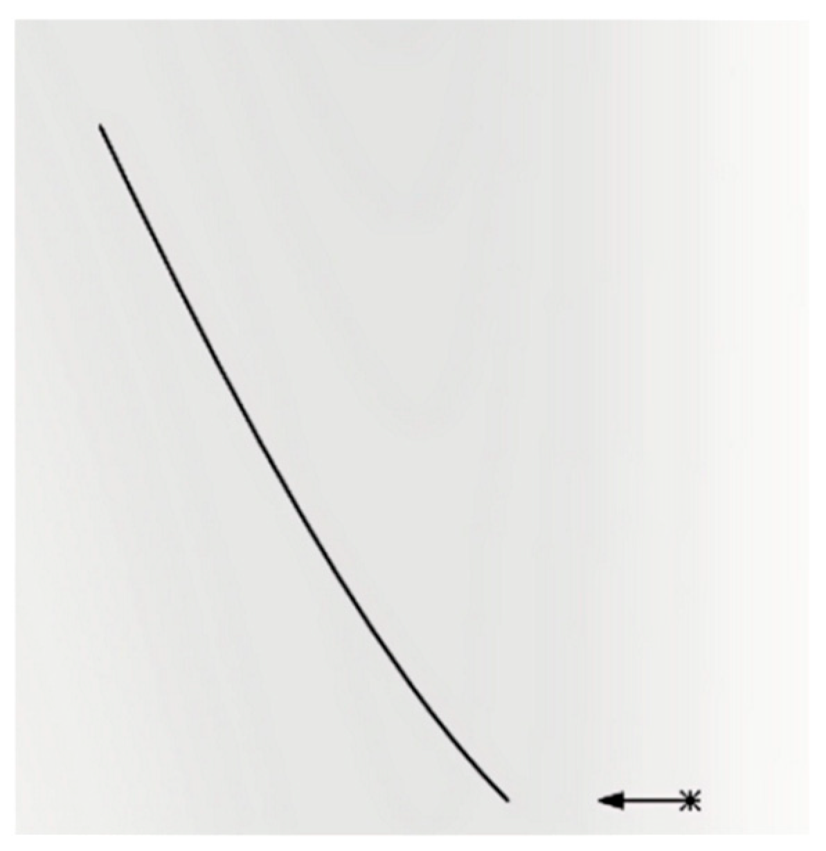
Based on the above recursive relationship, starting from the initial point Q 0 ( x 0 , z 0 ) , the coordinates of each point ( Q 1 , Q 2 , , Q n ) on the generatrix are calculated sequentially. Through iterative convergence, the complete contour of the generatrix of the total internal reflection freeform surface can be obtained. The 2-D contour plot of the designed total internal reflection freeform surface is shown in Figure 4 (the TIR freeform surface has a radial range of 0–12 mm and an axial height of 5–8 mm, matching the composite lens’s compact design).

2.2. Diffuse Reflection Freeform Surface Design

The diffuse reflection structure is an off-axis freeform surface (symmetric about the z-axis in Figure 2) with a 3D morphology synthesized from 2D contour curves. Its spatial range spans from the upper edge of the TIR freeform surface (point Q n in Figure 3) to the outermost boundary of the lens, with a maximum radial width of 35 mm and a height variation of 8–12 mm (optimized to avoid light blockage between the TIR and diffuse surfaces). The surface is discretized into 2000+ discrete points with a spacing of 0.05 mm, ensuring smooth curvature transitions (curvature radius variation < 0.1 mm−1) to prevent local light concentration.
As shown in Figure 5, E 1 denotes the irradiance of light reflected by the mirror surface, E 1 represents the irradiance of light incident on the rotationally symmetric diffuse reflection surface, and E is the total irradiance on the combined freeform surface, we can get:
E 1 = I 0 · c o s θ   [ x i 2 + z i 2 + ( x x i ) ] 2 E 1 = I 0 · c o s θ x 2 + z 2 E = E 1 + E 1  
Since the rotationally symmetric diffuse reflection surface is regarded as a series of continuously distributed second-order Lambertian light sources with rotational symmetry, this paper takes the irradiance distribution on the target plane in the X-Z 2-D coordinate system as an example [18]. Figure 6 shows the point P on the rotationally symmetric diffuse reflection surface and point T on the target plane can be represented by coordinate points P ( x i , 0 , z i ) and T ( x t , 0 , H ) on the 2-D plane. According to the knowledge of space vector, we can derive the following expression:
O U T = ( x t x , H z ) I N = ( x , z ) N = ( d z , d x ) c o s θ = O U T · N O U T · N
where O U T and I N respectively represent the light vector emitted and absorbed from the rotationally symmetric diffuse reflection surface, N is the normal vector on the freeform surface, θ is the angle between O U T and I N .
In this work, the rotationally symmetric diffuse reflection surface is modeled as an ideal Lambertian surface. Consequently, light emanating from this surface exhibits a cosine (Lambertian) radiation profile, scattering uniformly in all directions within the hemisphere above the surface. This fundamental assumption leads to the following relationship:
I θ = I 0 c o s θ
where I 0 is the maximum radiance in the direction normal to the rotationally symmetric diffuse reflection surface. Therefore, the irradiance distribution on the target illumination plane can be expressed as:
E = E · B R D F · c o s θ · d A d 2
where E is the irradiance received by the freeform surface (W/m2), as given by Equation (4), d is the distance between the rotationally symmetric diffuse reflection surface and the target illumination plane; and dA denotes the area element on the freeform surface. E as the general target-plane irradiance formula. The structure is defined as an ideal Lambertian reflector, meaning its bidirectional reflectance distribution function (BRDF) follows the cosine law. This ensures that light reflected from the surface is uniformly scattered within the upper hemisphere (relative to the local surface normal), with no directional dependence. The BRDF describes the reflectance properties of the freeform surface and is given by:
B R D F = ρ π
where ρ is the rotationally symmetric diffuse reflection surface reflectance, considering the practical scenario, the value of ρ is set to 0.85 in the calculations presented in this article. As shown in Figure 6a, substituting Equations (10)–(13) reduces the irradiance simulation algorithm for point T ( x t , 0 , H ) on the target plane, so we can get:
E t x t , 0 , H = i = 1 U E · ρ ·   [ x t x i · d z i + H + Z i · d x i ] π · ( x t x i ) 2 + ( H + z i ) 2 3 / 2   [ ( d z i ) 2 + ( d x i ) 2 ] 1 / 2
Equation (14) quantifies the irradiance on the target plane (at point T ( x t , 0 , H )) generated by light that reaches the diffuse reflective freeform surface via initial total internal reflection (TIR) and then undergoes diffuse reflection, where E t as the specific target-plane irradiance at point T. Correspondingly, as illustrated in Figure 6b, the irradiance distribution on the target illumination plane, generated by the secondary diffuse reflection event from this diffuse reflection surface acting as a Lambertian source, is derived as follows:
E t x t , 0 , H = i = 1 U E t x t , 0 , H · ρ ·   [ x t x i · d z i + H + z i · d x i ] π · ( x t x i ) 2 + ( H + z i ) 2 3 / 2   [ ( d z i ) 2 + ( d x i ) 2 ] 1 / 2
As shown in Figure 6c, point P on the rotationally symmetric diffuse reflection surface and point T on the target plane can be further represented as points P ( x i u 1 , 0 , z i u 1 ) and T ( x t u 1 , 0 , H ) in the X-Z 2-D plane, respectively. This paper assumes that there are N radiation points on the rotationally symmetric diffuse reflection surface, and each radiation point radiates to two non-adjacent points. Therefore, based on the above-described rotationally symmetric diffuse reflection surface, it can be further concluded that when the n-th diffuse reflection occurs, the illuminance distribution of the target illumination plane generated by the diffuse reflection freeform surface is:
E t u x t u 1 , 0 , H = i = 1 U E t ( u 1 ) x t u 2 , 0 , H · ρ ·   [ x t u 1 x i u 1 · d z i + H + z i u 1 · d x i ] π · ( x t u 1 x i u 1 ) 2 + ( H + z i u 1 ) 2 3 / 2   [ ( d z i ) 2 + ( d x i ) 2 ] 1 / 2
The superscripts of coordinates (e.g., x i u 1 , z i u 1 , x t u 1 ): They represent the spatial coordinates of discrete points on the diffuse surface ( x i , z i ) and target plane corresponding to the u-th diffuse reflection. The u − 1 index indicates that these coordinates are updated iteratively based on the previous ((u − 1)-th) reflection, ensuring consistency with the cumulative effect of multiple reflections. the subscript of irradiance (e.g., E t u ): denotes the target-plane irradiance generated by the u − th diffuse reflection on the diffuse surface.
According to the energy conservation constraint, the total radiant flux incident on the diffuse surface (from direct LED rays and TIR-reflected rays) must equal the flux scattered to the target plane (accounting for reflectance losses). Mathematically, this is expressed:
A diffuse E · d A = 1 𝜌 A target E t · d A
where A d i f f u s e is the area of the diffuse surface, E is the irradiance on the diffuse surface (Equation (9)), A t a r g e t is the target plane area, and E t is the target irradiance (Equation (14)). This constraint ensures no net energy loss in the reflection process (excluding material absorption). The tangent and normal vectors at the junction between the diffuse surface and the TIR surface (point Q n ) must be continuous to avoid light refraction losses at the interface. This is enforced by setting the 1st and 2nd derivatives of the diffuse surface’s 2-D contour (at the junction point) equal to those of the TIR surface’s generatrix (Equation (8)).
For each discrete point P i ( x i , 0 , z i ) on the initial contour, the irradiance E( P i ) (Equation (9)) and the corresponding target irradiance E t ( T j ) (Equation (14)) are calculated. The error between the simulated E t and the desired uniform irradiance ( E t a r g e t , d e s i r e d = 100   l u x ) is defined as:
δ = 1 N j = 1 N E t ( T j ) E t a r g e t , d e s i r e d E t a r g e t , d e s i r e d
where N = 128 × 128 (target plane grid resolution). The contour points are adjusted iteratively using the 4th-order Runge–Kutta algorithm to minimize δ . Each iteration updates the z-coordinate of P i based on the error gradient ( δ z i ), with a step size of 0.01 mm to ensure convergence. The iteration stops when δ < 3% (typically after 50–80 iterations), yielding the optimized 2-D contour (Figure 7a). The optimized 2-D contour is rotated 360° around the z-axis (with 0.5° angular increments) to form the 3-D diffuse reflection surface (Figure 7b).
The computationally designed 2-D contour profiles of the total internal reflection (TIR) freeform surface (derived as shown in Figure 4) and the diffuse reflective freeform surface (derived as shown in Figure 8a) were imported into SolidWorks® (2022 SP3.0) for 3-D reconstruction. The 2D contour of the composite freeform surface (Figure 8a) unifies the TIR and diffuse reflection surface profiles in the z-x plane, where the horizontal axis aligns with the x-axis of Figure 4 (TIR design) and the vertical axis aligns with the z-axis of Figure 3, ensuring consistency with the overall coordinate system. The resultant composite freeform lens geometry is presented in Figure 8 (The composite freeform lens (TIR + diffuse) has a maximum radial width of 25 mm and a volume < 10 cm3; the 2-D contour in Figure 8a uses a coordinate scale where 1 unit = 1 mm): Figure 8a displays the final 2-D contour profile of the integrated lens design, the 2D contour line of the composite freeform surface (in the z-x plane, with the horizontal axis representing the lateral direction (x-axis) and the vertical axis representing the axial direction (z-axis) of the lens). This contour integrates the TIR freeform surface generatrix (Figure 4) and diffuse reflection freeform surface contour (Figure 7a), serving as the blueprint for 3D reconstruction via rotational symmetry around the z-axis. And Figure 8b shows the corresponding 3D solid model of the fabricated lens component.
3. Results

Leveraging the design methodology outlined above, a composite freeform optical element integrating total internal reflection (TIR) and diffuse reflection functionalities was developed. Given the scale of the optical system relative to the LED source dimensions, the LED was modeled as a point source exhibiting a Lambertian radiant intensity distribution. The optical power of the LED source was set to 1 W, emitting at a wavelength of 630 nm for initial validation: minimal PMMA absorption (≥92% transmittance), standard for TracePro simulations, ensuring reliable theory-experiment correlation. Though 555 nm (CIE 1931 photopic peak) suits visual lighting, the design’s uniformity (>82%) and efficiency (>42%)—dependent on TIR-diffuse synergy—persist across 450–700 nm, aligning better with vision at 555 nm. And The composite freeform optical device is a solid structure fabricated from PMMA (refractive index n ≈ 1.49). This solid design is essential for realizing the TIR effect and integrating the diffuse reflection layer, ensuring both optical performance and structural stability. The optical performance of the designed system was simulated using TracePro (version 7.8.3) ray-tracing software. The target plane was discretized with a grid resolution of 128 × 128 pixels, spanning radii from 50 mm to 500 mm. The separation distance between the optical system and the target plane was varied between 150 mm and 1600 mm. To critically evaluate the efficacy and limitations of the proposed design, its simulated lighting efficiency and illumination uniformity were benchmarked against three representative conventional approaches: (i) hybrid diffuse-TIR freeform surface, (ii) diffuse-only freeform surface, and (iii) integrating sphere.
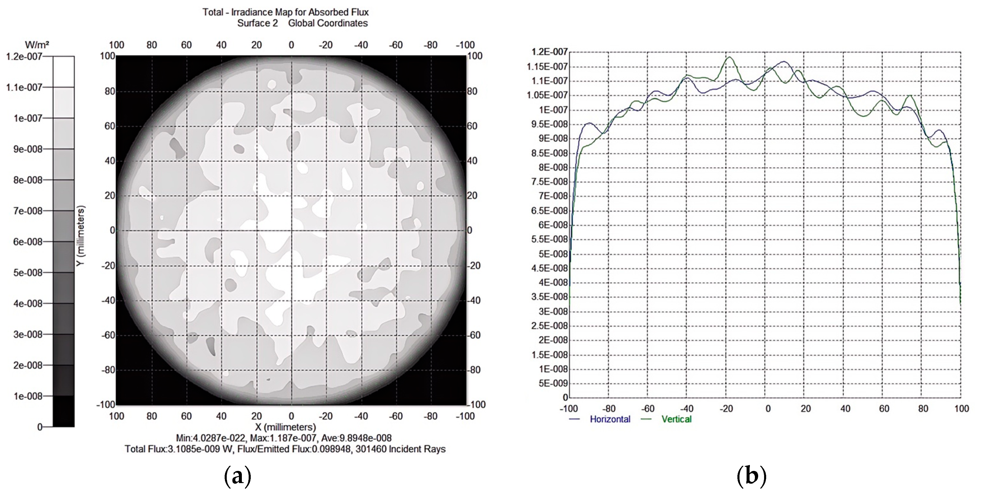
Figure 9 presents the experimental results of the lighting system designed in this paper. It can be observed from the results that when the distance between the light source and the target illumination plane is 400 mm and the radius of the target illumination plane is 100 mm, the irradiance uniformity reaches 83.35%. Table 1 systematically compares the simulated performance metrics of three distinct illumination systems—(i) hybrid diffuse-TIR freeform surface, (ii) diffuse-only freeform surface, and (iii) integrating sphere (standard parameters for small-scale LED indirect illumination testing)—across parametric variations in the LED-to-target-plane distance (50–500 mm) with a constant radius of the target illumination plane (100 mm). A 100 mm-diameter integrating sphere was modeled, with its inner surface coated in a high-reflectivity diffuse material (consistent with commercial models like the Thorlabs IS100 series—Thorlabs, Inc., with its headquarters in Newton, NJ, USA) for LED optical performance characterization and a 20 mm-diameter circular exit aperture was positioned on the sphere’s bottom surface, coaxial with the LED source. This aperture size was matched to the effective light-emitting area of our composite freeform lens (≈314 mm2) to eliminate geometric bias in uniformity and efficiency comparisons. And a circular optical baffle (diameter = 15 mm, thickness = 1 mm) was installed along the central axis of the integrating sphere, positioned 30 mm above the exit aperture. This baffle blocks direct light from the LED source to the exit aperture, ensuring that only light scattered by the sphere’s inner diffuse surface exits through the aperture—consistent with the working principle of standard integrating spheres for indirect illumination characterization and eliminating direct illumination bias in uniformity/efficiency measurements. Experimental data from three different lighting systems were compared by adjusting the distance from the light source to the target illumination plane and the radius of the target illumination plane. The results indicate that the lighting system designed in this paper improves both the irradiance uniformity and illumination efficiency of the target plane across various scenarios, thus verifying the effectiveness of the combined freeform surface design method. This method is applicable to various fields requiring uniform illumination.
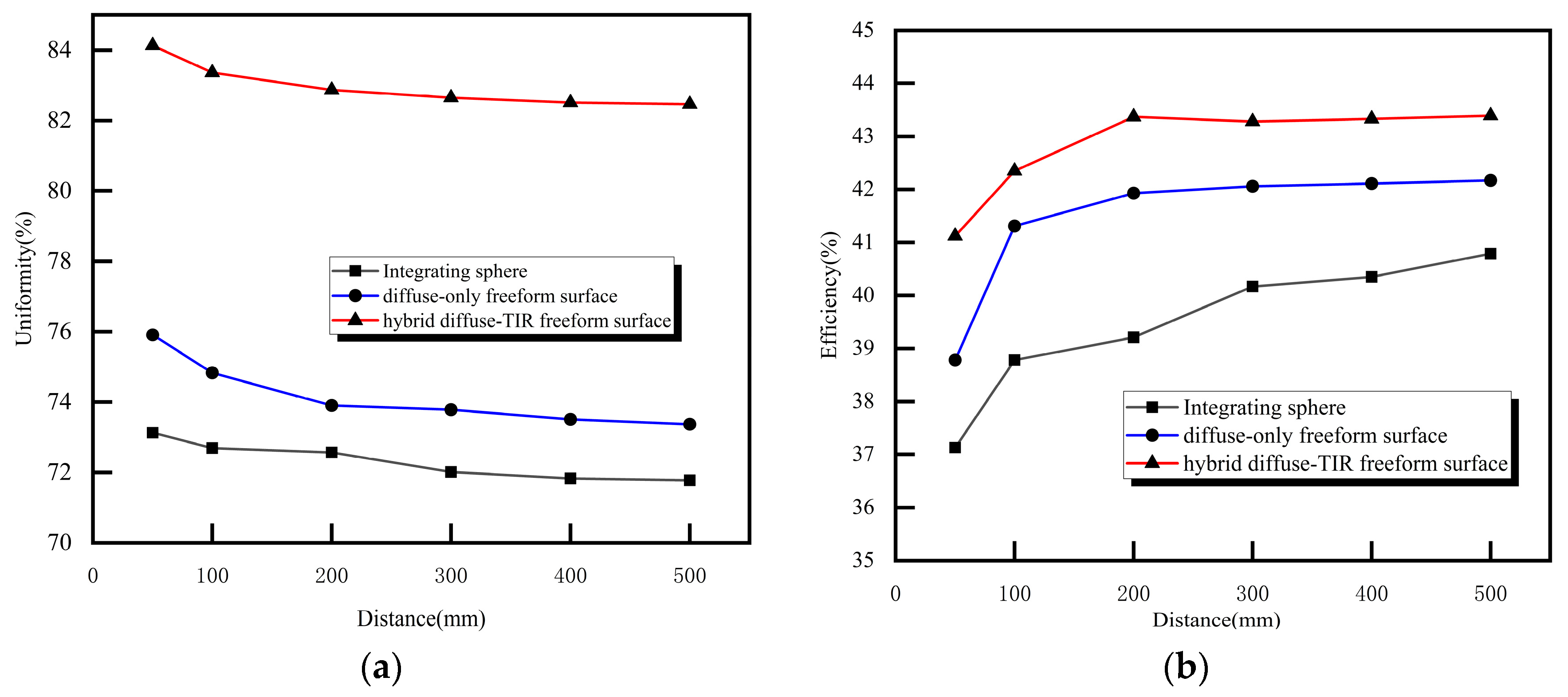
From Table 1, the practical optical efficiency of our hybrid TIR-diffuse system ranges from 41.12 to 43.39%, outperforming diffuse-only (38.78–42.17%) and integrating sphere (37.13–40.79%) systems. And we can be observed that approximately 50% of the total light rays emitted by the LED reach the target plane via the freeform surface designed in this study (i.e., light utilization efficiency), whereas traditional diffuse reflection systems (e.g., spherical diffuse reflectors) only achieve approximately 20% due to Fresnel losses and unregulated scattering—this theoretical advantage is validated by the practical efficiency gap in Table 1. As the illumination distance increases, the illumination efficiency of different illumination systems does not change significantly; however, there is a notable difference in irradiance uniformity. Compared with traditional illumination surfaces, the combined diffuse reflection freeform surface system exhibits superior illumination performance. Figure 10 illustrates the performance variation trends of different lighting systems on the target plane under various conditions.
Figure 10 illustrates the trends of irradiance uniformity and efficiency under different target illumination planes and illumination distances. It can be observed that the combined diffuse reflection freeform surface designed in this paper outperforms other traditional illumination systems in terms of both irradiance uniformity and illumination efficiency. Thus, the combined diffuse reflection freeform surface illumination system designed in this paper can be considered a feasible approach to achieve high irradiance uniformity and illumination efficiency.

4. Discussion

Due to the insufficient performance of LED lenses with a single freeform surface, the design method of double freeform surface lenses has attracted significant attention. However, a dual freeform surface cannot be uniquely determined without introducing additional constraints. Generally, the luminous flux efficiency and illuminance uniformity of dual freeform surface lenses are significantly superior to those of single freeform surface lenses. Compared with traditional diffuse reflection freeform surfaces, although Fresnel loss is minimized, luminous flux efficiency cannot be improved. Therefore, based on the emission characteristics of a single LED Lambertian source, this paper designs a combination of total internal reflection and diffuse reflection freeform surfaces. A key innovation of this work is the synergistic integration of TIR and diffuse reflection—a combination unattainable with transmissive designs. TIR relies on total internal reflection at the lens-air interface, which requires a continuous, low-loss optical path. Transmissive diffuse media disrupt this path by introducing refractive index inhomogeneities, preventing TIR from occurring (as scattered light cannot maintain the critical angle for total internal reflection). In our reflective design, the diffuse surface acts as a “secondary receiver” for TIR-reflected light (Path 1 in Figure 2): TIR collimates diverging LED rays and directs them to the reflective surface, which then scatters the light uniformly onto the target plane. The integration of TIR and diffuse reflection enhances optical efficiency by approximately 1–4% compared to conventional systems: at the same target distance (e.g., 500 mm), our hybrid system achieves 43.39% efficiency—approximately 1.22% higher than the diffuse-only system (42.17%) and approximately 2.60% higher than the integrating sphere (40.79%); at 50 mm, the hybrid system (41.12%) outperforms the diffuse-only (38.78%) and integrating sphere (37.13%) by approximately 2.34% and approximately 3.99%, respectively (efficiency comparisons in this study strictly follow “same-distance” principles, eliminating misleading cross-distance benchmarks).
It employs a total internal reflection structure to reduce the deflection angles of both incident and outgoing light rays, with the minimum Fresnel loss as a constraint condition. The 3-D space solution problem is compressed into several 2-D planes, and mathematical models for the total internal reflection freeform surface and diffuse reflection freeform surface are established according to Snell’s law. Subsequently, an iterative algorithm and the Runge–Kutta algorithm are used to solve the cross-sections of the two freeform surfaces in multiple directions (i.e., 2-D curves). These cross-sections are then closed and laid out using the 3-D modeling software SolidWorks to obtain the combined freeform surface lens. Simulation experiments have validated that its illumination uniformity and efficiency are superior to those of traditional diffuse reflection freeform surfaces. However, the method proposed in this study still has room for improvement, particularly as the lighting efficiency remains at a relatively low level. Feedback optimization design is also a critical component in LED lighting design. This paper only improves the accuracy of the surface morphology by increasing the number of cross-sections, without introducing the irradiance distribution of the illuminated surface as a feedback parameter for surface shape optimization. Therefore, in subsequent work, after experimental analysis, the irradiance of the target surface obtained from simulation experiments can be substituted into the original mathematical model. The model can then be adjusted to optimize the surface shape of the resulting freeform surface, thereby further enhancing the irradiance uniformity and illumination efficiency of the target surface.
In addition, this paper selected a single LED for investigation, while excluding the consideration of multiple LED arrays from the research scope. Regarding extending to multiple LEDs, we will consider the critical angle constraint for TIR in subsequent research. For LEDs in a multi-LED array, rays from edge LEDs may initially propagate at angles below θ c (failing to meet TIR conditions). To address this, we propose two feasible modifications, which will be added to the Discussion section of the revised manuscript: (i) Spatial arrangement optimization: Position each LED such that its incident angle on the TIR surface falls within θ c , 90 ° . This is achievable by adjusting the array’s pitch and distance from the TIR surface (e.g., a hexagonal array with LED centers spaced 1.2× the TIR surface’s local curvature radius). (ii) Hybrid optical path: For rays below θ c , integrate a micro-prism array on the TIR surface to redirect these rays to meet TIR conditions (micro-prisms adjust the incident angle by ~5–15°, ensuring θ θ c .

5. Conclusions

This paper develops an illumination system combining total internal reflection and diffuse reflection freeform surfaces based on a multiple diffuse reflection freeform surface model. Experimental results validate its effectiveness and feasibility. The composite freeform surface illumination model designed in this paper exhibits high irradiance uniformity and illumination efficiency, which is significantly superior to other traditional diffuse reflection illumination systems. Furthermore, this method has a certain degree of universality: it only requires optimizing and adjusting the target plane parameters to meet the lighting requirements of other fields, thereby effectively expanding the application prospects of diffuse indirect lighting in industrial production and daily life.

Author Contributions

Conceptualization, X.X., J.R. and Z.Z.; methodology, X.X., X.L. and Y.P.; software, X.X. and Y.P.; validation, X.X., J.R. and Z.Z.; formal analysis, X.X., J.R. and Y.P.; investigation, J.R., X.L. and Z.Z.; resources, J.R., X.L. and Y.P.; data curation, X.X. and Z.Z.; writing—original draft preparation, X.X.; writing—review and editing, X.X., J.R. and X.L.; visualization, X.X. and Z.Z.; supervision, J.R. and X.L.; project administration, X.X., J.R. and Z.Z.; funding acquisition, X.X., J.R. and Z.Z. All authors have read and agreed to the published version of the manuscript.

Funding

This research was funded by Science and Technology Project of Jiangxi Provincial Department of Education (GJJ2403802), Jiangxi Provincial Natural Science Foundation (20242BAB25104, 20242BAB25057), Key R&D Program Project of Jiangxi Province (20232BBE50012), and Education Department Science and Technology Plan Project-Youth Science Fund Project (GJJ2403806).

Institutional Review Board Statement

Not applicable.

Informed Consent Statement

Not applicable.

Data Availability Statement

The data underlying the results presented in this paper are not publicly available at this time, but may be obtained from the authors upon reasonable request.

Conflicts of Interest

The authors declare no conflicts of interest.

References

  1. Chiang, C.W.; Hsu, Y.K.; Pan, J.W. Design and demonstration of high efficiency anti-glare LED luminaires for indoor lighting. Opt. Exp. 2015, 23, 12–23. [Google Scholar] [CrossRef] [PubMed]
  2. Jiang, J.; To, S.; Lee, W.; Cheung, B. Optical design of a freeform TIR lens for LED streetlight. Optik 2010, 121, 1761–1765. [Google Scholar] [CrossRef]
  3. Wang, J.; Liang, Y.; Xu, M. Design of a See-Through Head-Mounted Display with a Freeform Surface. J. Opt. Soc. Korea 2015, 19, 614–618. [Google Scholar] [CrossRef]
  4. Wang, X.; Li, X.; Zhang, Q.; Wei, W.; Liu, E. Efficient Testing Light Path for Aspherical Surfaces Based on Secondary Imaging. Photonics 2025, 12, 485. [Google Scholar] [CrossRef]
  5. Pan, J.-W.; Su, Y.-C.; Chen, Y.-S. Secondary optical element design for intracorporeal LED illumination system. Opt. Lett. 2014, 39, 224–227. [Google Scholar] [CrossRef]
  6. Cai, X.; Quan, L.; Wu, J.; He, Y. Night-time disability glare of constant-light LED traffic monitoring fill light. Light. Res. Technol. 2021, 53, 595–608. [Google Scholar] [CrossRef]
  7. Ren, C.; Meng, Q. Design Method for Freeform Off-Axis Three-Mirror Anastigmat Optical Systems with a Large Field of View and Low Error Sensitivity. Photonics 2024, 11, 211. [Google Scholar] [CrossRef]
  8. Xu, S.; Peng, X.; Song, C. Adaptive Freeform Optics Design and Multi-Objective Genetic Optimization for Energy-Efficient Automotive LED Headlights. Photonics 2025, 12, 388. [Google Scholar] [CrossRef]
  9. Li, Y.; Feng, Z.; Cheng, D.; Wang, Y. Designing double freeform surfaces for large ray bending irradiance tailoring of extended LED sources. Opt. Express 2021, 29, 13469–13485. [Google Scholar] [CrossRef] [PubMed]
  10. Huang, J.; Jiang, S.; Yang, H.; Czuma, R.; Yang, Y.; Kozel, F.A.; Jiang, H. Portable diffuse optical tomography for three-dimensional functional neuroimaging in the hospital. Photonics 2024, 11, 238. [Google Scholar] [CrossRef]
  11. Liu, X.; Zhu, J. Design method of freeform off-axis multi-mirror optical systems. Photonics 2022, 9, 534. [Google Scholar] [CrossRef]
  12. Liu, B.; Jin, X.; Zhu, Z. Uniform illumination design based on LED array and diffuse reflection freeform surface. J. Appl. Opt. 2014, 35, 598–602. [Google Scholar]
  13. Tsuei, C.-H.; Sun, W.-S. Momentary adjustment means for simulating the sunlight color temperature, hues and brightness with RGB LEDs in indoor lighting. Phys. Procedia 2011, 19, 239–243. [Google Scholar] [CrossRef]
  14. Zhu, Z.-M.; Qu, X.-H.; Jia, G.-X.; Ouyang, J.-F. Uniform Illumination Design by Configuration of LED Array and Diffuse Reflection Surface for Color Vision Application. J. Disp. Technol. 2011, 7, 84–89. [Google Scholar] [CrossRef]
  15. Zhu, Z.-M.; Liu, H.; Chen, S.-M. The Design of Diffuse Reflective Free-Form Surface for Indirect Illumination with High Efficiency and Uniformity. IEEE Photonics-J. 2015, 7, 1–10. [Google Scholar] [CrossRef]
  16. Zhu, Z.-M.; Sun, X.; Peng, B. The Design of Diffuse Reflective Off-Axis Surface for Noncircular LED Arrays. IEEE Photonics-J. 2016, 9, 1600210. [Google Scholar] [CrossRef]
  17. Lan, D.; Wei, W. TIR Lens-based optical system design for dynamic star simulator illumination. Illum. Eng. J. 2023, 34, 22–28. [Google Scholar]
  18. Zhu, Z.; Xu, X.; Sun, X.; Wang, X. Establishment and solution for a mathematical model of multiple diffuse reflection. IEEE Photonics-J. 2020, 12, 6500917. [Google Scholar] [CrossRef]
Figure 1. Flowchart of this paper design method for LED uniform illumination.
Photonics 12 01025 g001
Figure 2. The cross-sectional profile of the combined freeform surface illumination system.
Photonics 12 01025 g002
Figure 3. Calculation of total internal reflection freeform surface.
Photonics 12 01025 g003
Figure 4. The 2-D contour of the total internal reflection freeform surface.
Photonics 12 01025 g004
Figure 5. The irradiance of the diffuse reflection freeform surface.
Photonics 12 01025 g005
Figure 6. The schematic diagram of the diffuse reflection freeform surface for diffuse reflection occurs, (a) first, (b) second, (c) multiple.
Photonics 12 01025 g006
Figure 7. (a) The 2-D contour of the diffuse reflection freeform surface (unit: mm), (b) the 3-D diffuse reflection freeform surface.
Photonics 12 01025 g007
Figure 8. (a) The 2-D contour line of the composite freeform surface, (b) the entity model of the lens.
Photonics 12 01025 g008
Figure 9. Simulation results of the irradiation uniformity over the target plane at the distance Z = 400 mm and a circular area with the radius R = 100 mm. (a) Shows the irradiance distribution on the target illumination plane, while (b) presents the irradiance distribution along the horizontal and vertical axes.
Photonics 12 01025 g009
Figure 10. (a) Trend chart of irradiance uniformity at different illumination distances with a constant radius of the target illumination plane, (b) Trend chart of irradiance efficiency at different illumination distances with a constant radius of the target illumination plane.
Photonics 12 01025 g010
Table 1. The lighting performance of three different illumination systems.
DistanceUniformityEfficiency
Hybrid Diffuse-TIR Freeform SurfaceDiffuse-Only Freeform Surface Integrating SphereHybrid Diffuse-TIR Freeform SurfaceDiffuse-Only Freeform Surface Integrating Sphere
50 mm84.13%75.91%73.13%41.12%38.78%37.13%
100 mm83.36%74.83%72.69%42.35%41.31%38.78%
200 mm82.87%73.9%72.57%43.37%41.93%39.21%
300 mm82.65%73.78%72.01%43.28%42.06%40.17%
400 mm82.51%73.51%71.83%43.33%42.11%40.35%
500 mm82.46%73.37%71.78%43.39%42.17%40.79%
Disclaimer/Publisher’s Note: The statements, opinions and data contained in all publications are solely those of the individual author(s) and contributor(s) and not of MDPI and/or the editor(s). MDPI and/or the editor(s) disclaim responsibility for any injury to people or property resulting from any ideas, methods, instructions or products referred to in the content.