Article

An Off-Axis Catadioptric Division of Aperture Optical System for Multi-Channel Infrared Imaging

Key Laboratory of Opto-Electronic Information Technology, Ministry of Education, School of Precision Instruments and Opto-Electronics Engineering, Tianjin University, Tianjin 300072, China
*
Authors to whom correspondence should be addressed.
Photonics 2025, 12(10), 1008; https://doi.org/10.3390/photonics12101008
Submission received: 23 August 2025 / Revised: 8 October 2025 / Accepted: 10 October 2025 / Published: 13 October 2025
(This article belongs to the Section Optical Interaction Science)

Abstract

Multi-channel optical systems can provide more feature information compared to single-channel systems, making them valuable for optical remote sensing, target identification, and other applications. The division of aperture polarization imaging modality allows for the simultaneous imaging of targets in the same field of view with a single detector. To overcome the limitations of conventional refractive aperture-divided systems for miniaturization, this work proposes an off-axis catadioptric aperture-divided technique for polarization imaging. First, the design method of the off-axis reflective telescope structure is discussed. The relationship between optical parameters such as magnification, surface coefficient, and primary aberration is studied. Second, by establishing the division of the aperture optical model, the method of maximizing the field of view and aperture is determined. Finally, an off-axis catadioptric cooled aperture-divided infrared optical system with a single aperture focal length of 60 mm is shown as a specific design example. Each channel can achieve 100% cold shield efficiency, and the overall length of the telescope module can be decreased significantly. The image quality of each imaging channel is close to the diffraction limit, verifying the effectiveness and feasibility of the method. The proposed off-axis catadioptric aperture-divided design method holds potential applications in simultaneous infrared polarization imaging.

1. Introduction

Modern optical systems are evolving towards multiple information channels [1,2,3], multi-dimensional [4,5], and miniaturization [6,7,8,9,10,11,12,13]. The infrared polarization imaging detection technique offers significant advantages over conventional optical imaging methods. It can enhance contrast and capture additional details about the target features under complex environments [11,14]. Therefore, it has a wide application prospect in remote sensing imaging, industrial detection, and other applications [15,16]. Generally speaking, the polarization imaging systems primarily comprise division of time polarimeters (DoTPs), division of amplitude polarimeters (DoAmPs), division of aperture polarimeters (DoAPs), and division of focal plane polarimeters (DoFPs) [17,18,19]. The division of time polarimeter rotates the polarizer to acquire information on various polarization states. However, the revolving optical components may introduce image registration issues requiring a rigorous testing environment [20,21]. The division of amplitude polarimeter can accomplish multi-detector polarization optical imaging by using polarization modulation devices and beam-splitting prisms [2,22]. The division of focal plane polarimeter requires the addition of metal wire grid micro polarizers in various directions in front of the photosensitive chip of detectors. This approach demands high fabrication accuracy for the micro-polarizers [23,24,25]. The division of aperture polarimeter introduces the aperture-divided lens group into the conventional optical lens to obtain different polarization images of the same target from different positions of a single detector, which has the advantages of low cost and high real-time performance [26,27,28,29,30].
The research on the division of aperture optical design methods began in 2005. J. Larry Pezzaniti et al. [31] developed an aperture-divided Medium Wave Infrared (MWIR) imaging polarimeter with a focal length of 100 mm and an F-number of 2.3, which can obtain information on different polarization states between different channels simultaneously. In 2007, Sean Moultrie et al. [27] designed an imaging polarimeter in the visible light range, which simultaneously captures four sub-images on a single CCD array for collecting three Stokes components and radiation information. In 2013, Hucheng He et al. [32] analyzed the relationship between imaging quality and crosstalk of polarization imaging optical systems using an optical transfer matrix. In 2015, Tingkui Mu et al. [33] proposed a system error calculation model for aperture-divided polarization imaging, demonstrating superior performance in terms of noise disturbance. In 2018, Xiaolong Wang et al. [34] designed an aperture-divided and hyperspectral imaging system based on the orthogonal dual polarization method and acousto-optic tunable filter, which can simultaneously obtain spectral and polarization information of static and dynamic targets. In the same year, Yongpeng Su et al. [35] designed an aperture-divided MWIR imaging optical system with different wavebands. By adding filters in different aperture-divided channels, the simultaneous imaging of targets in different bands on the same detector is realized. The conventional DoAP systems generally include a refractive structure with numerous modules cascaded in the optical channel. This configuration not only involves a complex optical and mechanical structure, but also results in an excessively long axial length. These factors hinder the miniaturization and lightweight property of the multi-channel system. Consequently, it is particularly important to study a compact and unobstructed aperture-divided polarization imaging system.
A telescope system with a wide aperture, long focal length, and high resolution is necessary to detect and identify distant targets. However, the bulk and weight will severely limit its practical applications if a conventional refractive structure is used. Off-axis reflective optical systems offer a novel design concept for telescopic structures, featuring advantages such as a high degree of spatial folding, an unobscured aperture, and freedom from chromatic aberration. Cook [36] proposed a compact Three-Mirror Anastigmat (TMA) structure with an aperture offset in a patent. Furthermore, related studies introduced optical systems based on the off-axis aperture principle [37,38], verifying the feasibility of this method for achieving beam deviation.
Building on these developments, we propose a design strategy for an off-axis catadioptric aperture-divided system working in the infrared band to improve the compactness and image contrast of the multi-channel imaging system. The initial structure of the aperture off-axis reflective telescope is obtained by establishing the relationship between optical parameters and Seidel aberration. Then, we analyze the parameter correlation between the ideal structure model of the aperture-divided array and the cooled optical system. The provided example enables different polarization channels to be closely distributed on the image plane, resulting in a compact system capable of real-time imaging.

2. Theoretical Basis

2.1. The Overall Framework of the Aperture-Divided Optical System

This work presents an off-axis catadioptric aperture-divided optical system that consists of a telescope subsystem and four aperture-divided sub-systems. Its concept design framework is illustrated in Figure 1. To minimize the volume of the integral aperture-divided system, the telescope subsystem uses the afocal off-axis reflection structure to compact the optical system. The beam is then imaged independently in different sections of the detector using the aperture-divided module. Four independent polarization states are captured by the detector’s four unique quadrants, which makes it easier to fuse polarization data further.

2.2. Design Method of the Off-Axis Two-Mirror Afocal Optical Structure

The telephoto optical system is an optical system that has no divergence or focusing impact on the beam, resulting in the effect of parallel light input and output. In the aperture-divided optical system, to reduce the aperture of subsequent optical components and the processing cost, the telescope system also plays the role of reducing the beam aperture. The two most prevalent telescope systems are the Kepler and Galileo structures. The Kepler telescope system consists of two groups of optical elements with positive focal power. Typically, a field stop is added to the intermediate image plane to minimize stray light outside the field of view. The Galileo telescope system is composed of the positive and negative focal power lens groups. There is no intermediate image plane in the middle of the optical system.
In this paper, the off-axis two-mirror afocal optical structure (OTAOS) is used to replace the traditional refractive telescope structure. The OTAOS mainly consists of the Kepler telescope construction with an intermediate image plane and the Galileo telescope structure without an intermediate image plane, as shown in Figure 2.
The initial structure of the OTAOS can be derived from the coaxial structure. Starting from a coaxial design optimized with Seidel aberration theory, the system is then offset, either via aperture or field displacement, to achieve an unobscured configuration [39]. The afocal coaxial two-mirror optical model as shown in Figure 2 is constructed. After entering the optical system, parallel incident light is reflected by the primary mirror (PM) and the secondary mirror (SM) and then exits as a parallel beam. For the reflection system, the refractive indices of the object space and the image space in the air medium satisfy the conditions as follows: n 1 = n 2 = 1 and n 1 = n 2 = 1 . The paraxial incidence heights on the PM and SM are denoted as h 1 and h 2 , with focal lengths f 1 and f 2 , respectively. The paraxial convergence angles of the mirrors are given by u 1 = u 2 = 0 , and u 1 = u 2 = h 1 f 1 = h 2 f 2 . The Lagrange invariant is expressed as J = n u y = n u y , where y and y are the object and image heights, respectively. The radii of the PM and SM are R 1 = 2 f 1 and R 2 = 2 f 2 , and the relationships between the conic coefficient and quadric surface coefficients are k 1 = e 1 2 and k 2 = e 2 2 , respectively. Finally, the magnification of the telescopic system is defined as Γ = f 1 f 2 = R 1 R 2 . The optical design and analysis in this work adhere to the standard Cartesian sign convention.
The monochromatic aberrations include spherical aberration, coma, astigmatism, field curvature, and distortion. According to the third-order aberration theory and the wave aberration theory of the aspherical surface, the sum of the five monochromatic Seidel aberrations of the OTAOS can be expressed by the following equation. Here, S I , S I I , S I I I , S I V , and S V represent the Seidel sum of spherical aberration, coma, astigmatism, field curvature, and distortion [40,41,42], respectively.
S I = h P + h 4 K S I I = y P J W + h 3 y K S I I I = y 2 h P 2 J y h W + J 2 ϕ + h 2 y 2 K S I V = Π h S V = y 3 h 2 P 3 J y 2 h 2 W + J 2 y h ( 3 ϕ + Π h )     J 3 1 h 2 Δ 1 n 2 + h y 3 K
The expressions for the Seidel sums in Equation (1) are consistent with those given in Ref. [42]. In particular, the expressions in Equation (1) incorporate the following parameters.
P = ( Δ u / Δ 1 n ) 2 Δ u n W = ( Δ u / Δ 1 n ) Δ u n Π = Δ ( n u ) / n u ϕ = Δ u n / h K = Δ n k / R 3
Through further derivation, the following equations illustrate the quantitative relationships between the optical characteristics of the five monochromatic aberrations in the afocal two-mirror optical system and the sum of the Seidel aberrations.
S I = 2 h 1 4 R 1 3 Γ 1 e 2 2 + e 1 2 Γ Γ S II = 2 h 1 3 R 1 3 1 + e 1 2 y 1 1 + e 2 2 y 2 S III = 2 h 1 2 R 1 3 1 + e 1 2 y 1 2 1 + e 2 2 Γ y 2 2 S IV = 2 R 1 ( 1 Γ ) S V = 2 h 1 R 1 3 1 + e 1 2 y 1 3 3 + e 2 2 Γ 2 y 2 3
According to Equation (3), when the quadric surface coefficients of the PM and SM meet the conditions e 1 2 = e 2 2 = 1 (that is, when the PM and SM are paraboloids), S I = S II = S III = 0 is established. The spherical aberration, coma, and astigmatism of the system can be automatically corrected. The magnification of the system can be understood as the reciprocal of the obscuration ratio, and the magnification directly affects the size of the field curve of the optical system. When the magnification of the system satisfies Γ = 1 , then S IV = 0 , and the field curve of the system is 0. However, the magnification system has no practical significance here.
According to the above analysis, the aberration evaluation function of the off-axis two-mirror afocal optical system can be established. The function is determined by the following key variables: the radius of the PM, the quadric surface coefficients of the PM and SM, and the system magnification. The aberration evaluation function is obtained by multiplying the corresponding Seidel aberration composite numbers with different weight factors, as shown in the following equation. The weight factors of the Seidel sum for the five monochromatic aberrations are represented by w i   ( i = 1 , 2 , 3 , 4 , 5 ) , respectively.
F = f R 1 , e 1 2 , e 2 2 , Γ = w 1 S I + w 2 S II + w 3 S III + w 4 S IV + w 5 | S V |

2.3. Calculation of the Aperture Offset for Off-Axis Afocal Systems

After the coaxial system is obtained, the off-axis structure is obtained by using the method of aperture off-axis. The aperture off-axis means that a part of the entrance pupil of the original system is selected as the pupil of the new optical system. A is the pupil size of the original coaxial system, D is the pupil size of the off-axis system, and their relationship can be expressed as:
A = 2 D + 2 d 1 ω 1 α = 2 Γ D Γ 1 ω R 1
where d 1 is the distance between the PM and SM, ω is the half field of view, and α is the obscuration ratio of the SM to the PM of the original coaxial structure. In addition, the off-axis value of the aperture h o f f can be expressed by:
h o f f = 1 2 ( A α + D )

2.4. Aperture-Divided Ideal Optical System Model

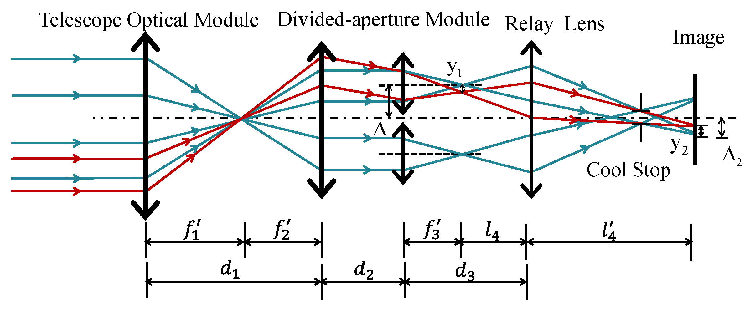
To explain the imaging relationship of the aperture-divided module in detail, the ideal initial structure model of the aperture-divided off-axis optical module is established, and its structural diagram is shown in Figure 3. The whole structure comprises a telescope optical module, four aperture-divided optical modules, and a relay structure. The focal lengths of the imaging objectives in the telescopic objective are f 1 and f 2 , respectively. The focal length of the aperture-divided objective is f 3 , the focal length of the relay lens is f 4 , and the spacings between the lens groups are d 1 , d 2 , and d 3 , respectively. The rays for the entire optical system and the sub-aperture are distinguished by different colors.
The relay lens group conjugates the intermediate image plane after the aperture-divided lens group to the final imaging detector. The object distance of the intermediate image plane relative to the relay mirror group is l 4 , and the image distance is l 4 , which can be obtained according to the classical imaging equation,
1 l 4 1 l 4 = 1 f 4
The off-axis value of the aperture-divided module relative to the original co-aperture optical system is Δ , and the image plane height of the aperture-divided module is y 1 . The off-axis value of the image plane center relative to the central optical axis after imaging through the relay objective is Δ 2 . The image plane size is y 2 . The transverse magnification is β 4 . The relative relationship is shown in the following equation.
β 4 = y 2 y 1 = Δ 2 Δ 1 = l 4 l 4
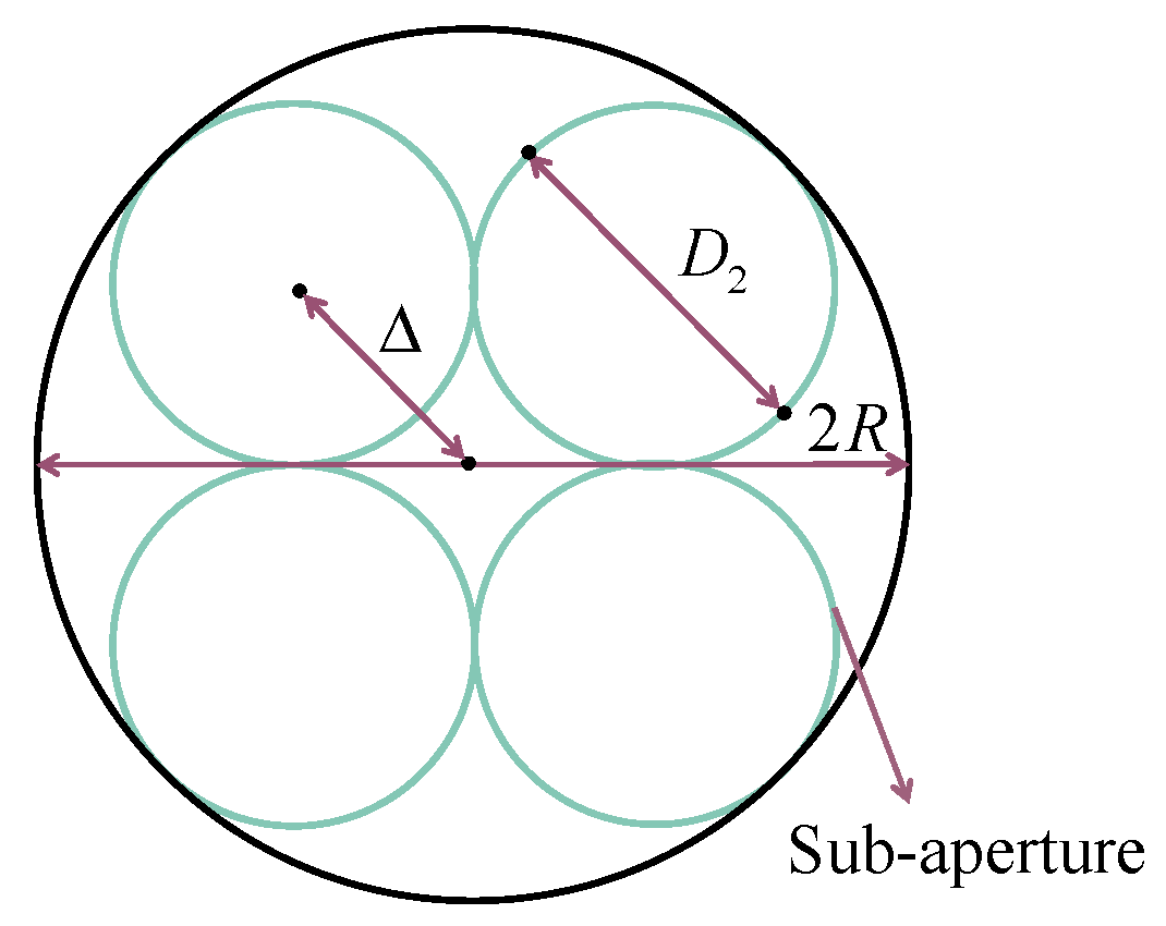
Since the pixel size of the infrared detector is larger than that of the visible light band, increasing the detector’s usage rate is essential to preserving more information about the detecting target. The image plane of each channel of the divided-aperture should be distributed as far as possible so that the image plane center of the subsystem is located in the center of the four quadrants of the detector. Figure 4 shows the layout diagram of the aperture-divided system, where the decenter value of the aperture-divided system is Δ , the circumradius of the aperture-divided system is R , and the outer diameter of the optical system with the divided aperture is D 2 .
The geometric relationship between the decenter value of the aperture-divided system and the overall system is shown in the Equation (9). To prevent the aperture-divided lens groups of separate channels from overlapping, the off-axis value of the aperture-divided group Δ shall not be less than 0.707 times the outer diameter of the aperture-divided optical system D 2 .
Δ + D 2 2 = R Δ 2 + Δ 2 = D 2 2

3. System Design

3.1. Detection Performance Analysis

The working distance of the infrared detection system is related to system parameters, atmosphere, targets, signal processing, and other factors. The working distance of the optical infrared detection system is analyzed by using the R. D. Hudson infrared system operating range equation [43], which is expressed as the following equation:
L 2 = π D 0 τ 0 τ a D J 2 F A d f 2 1 2 t int S N R
where L represents the distance from the target to the infrared system, D 0 denotes the effective aperture diameter of the infrared optical system, F signifies the F number of the optical system, D stands for the detectivity, τ 0 represents the transmittance of the optical system, τ a indicates the atmospheric transmittance, t int represents the integration time of the detector, A d denotes the photosensitive area of the detector pixel, J represents the total radiation of the target within the working wavelength band, and S N R signifies the signal-to-noise ratio of the output signal from the infrared system.
Equation (10) shows that the detection distance is determined by the pixel size of detectors, the integration time, and the effective aperture diameter of optical systems. Given that the infrared aperture-divided system’s single aperture is smaller than the entire structure, it is essential to increase the aperture diameter and minimize the number of lenses while adhering to the specifications of geometric size, weight, and environment.
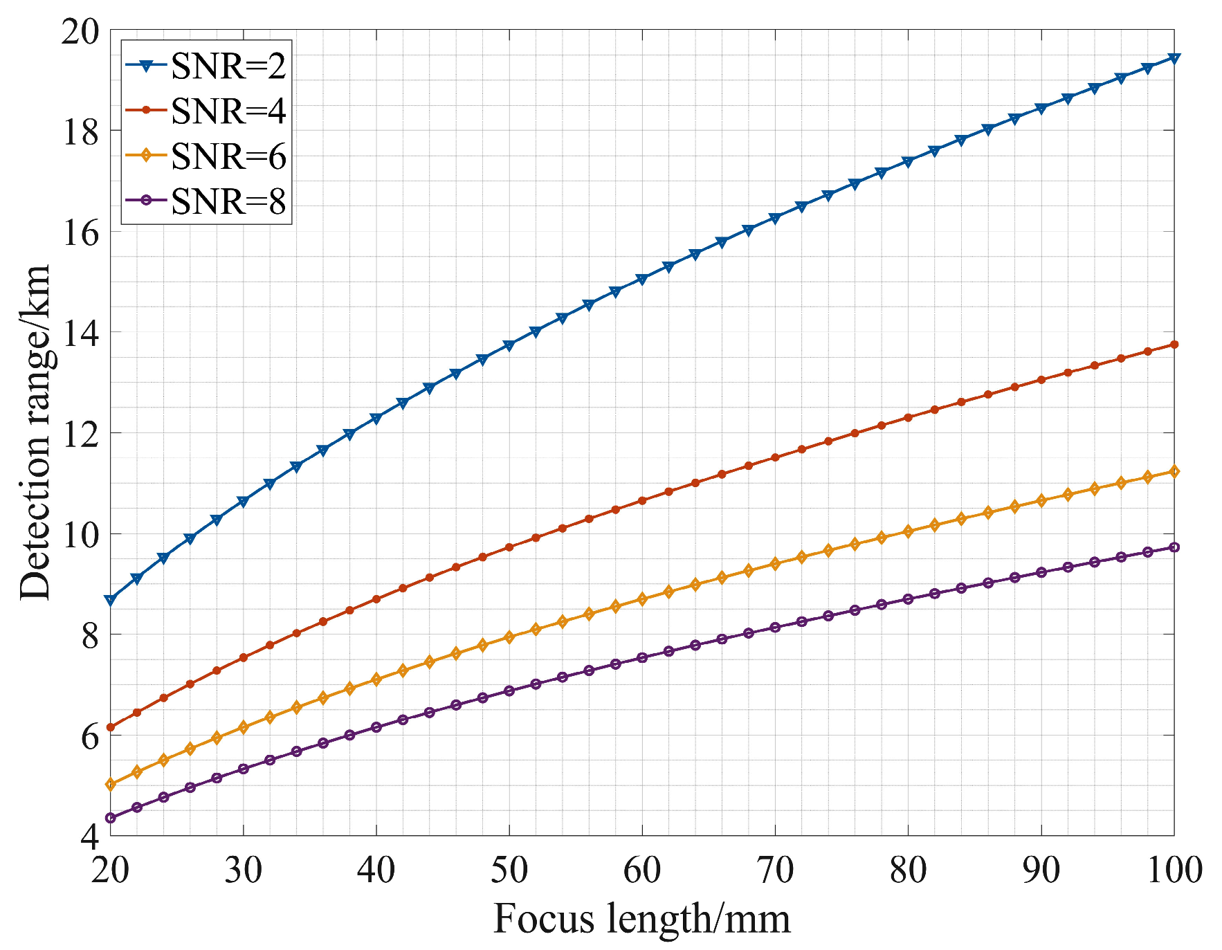
The selected detector is a cooled MWIR detector with a working wavelength range of 3.7–4.8 μm, pixel number of 640 × 512, pixel size of 15 μm, and F-number of 2.0. The technical characteristics of the system can be determined if the focal length of the infrared aperture-divided system can be ascertained, followed by the entrance pupil diameter of the optical system. The photosensitive area A d is determined by the detector pixel size. The specific detectivity D is 3 × 10 11 cm Hz 1 / 2 / W , and the detector integration time is 0.7 ms. The atmospheric transmittance τ a is obtained from the MODTRAN model for a 50 km range under standard conditions (23 km visibility) in the MWIR band. The effective aperture diameter D 0 , transmittance τ 0 , and F-number F are derived directly from the designed optical system. The optical system transmittance is determined based on the number of lenses and the parameters of the single-layer anti-reflection coating and is set to 75% in this work. Figure 5 illustrates this relationship between the infrared detecting system’s focal length and detection distance. If the limit signal-to-noise ratio is 4.0, the focal length of the infrared aperture-divided system should be at least 50 mm to achieve detection at a distance greater than 10 km.

3.2. Design Parameter

To confirm the design method of the off-axis catadioptric aperture-divided optical structure mentioned above, a design case is introduced to support it. Its technical indicators are shown in Table 1. The technical parameters of the design case are selected according to the relationship between the detection performance of the optical system and the parameters of the optical system. The diameter of the photosensitive surface of the cooled MWIR detector is 12.3 mm, and the diameter of the image plane of the single-channel optical system is 6.15 mm. According to the analysis in Section 3.1, to ensure the detection ability and resolution ability of the optical system, the focal length of the aperture-divided system is selected as 60 mm, and then the corresponding field of view can be obtained.

4. Design Case and Simulation Results

4.1. Structure of the Afocal Optical Telescopic System

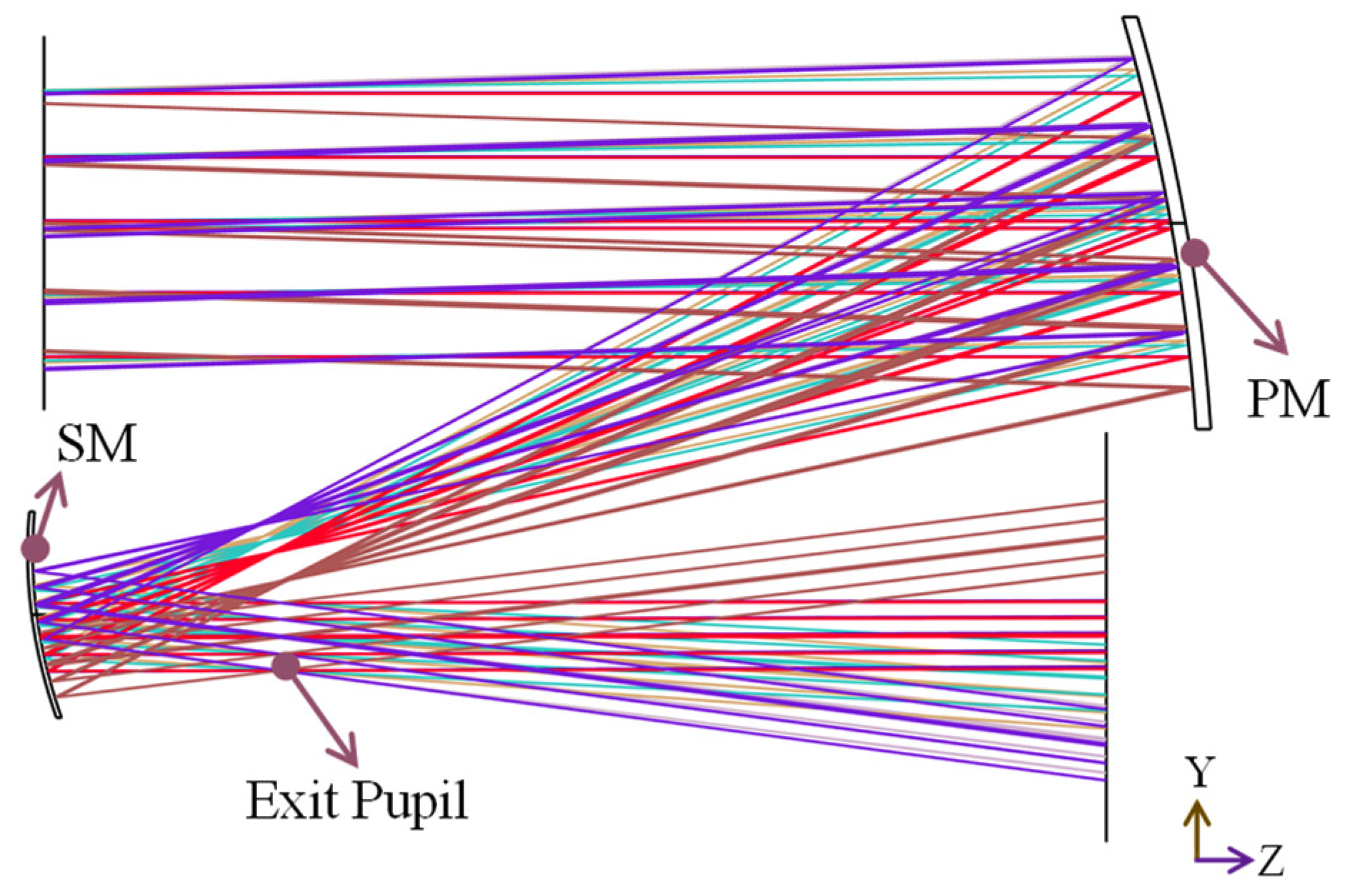
Based on the design theory in Section 2.2 and Section 2.3, the initial solution of a coaxial afocal optical telescopic structure is obtained by solving the parameters of radii, conic constant, and system magnification. The radii of the PM and the SM of the coaxial optical telescope structure are −449.6 mm and 114.1 mm, respectively. Both surfaces are paraboloids, and the quadric surface coefficient meets e 1 2 = e 2 2 = 1 . Then, the optical system was designed, simulated, and analyzed using the commercial optical design software Zemax 2006. The obscuration ratio of the structure is 0.253, and its layout is shown in Figure 6.
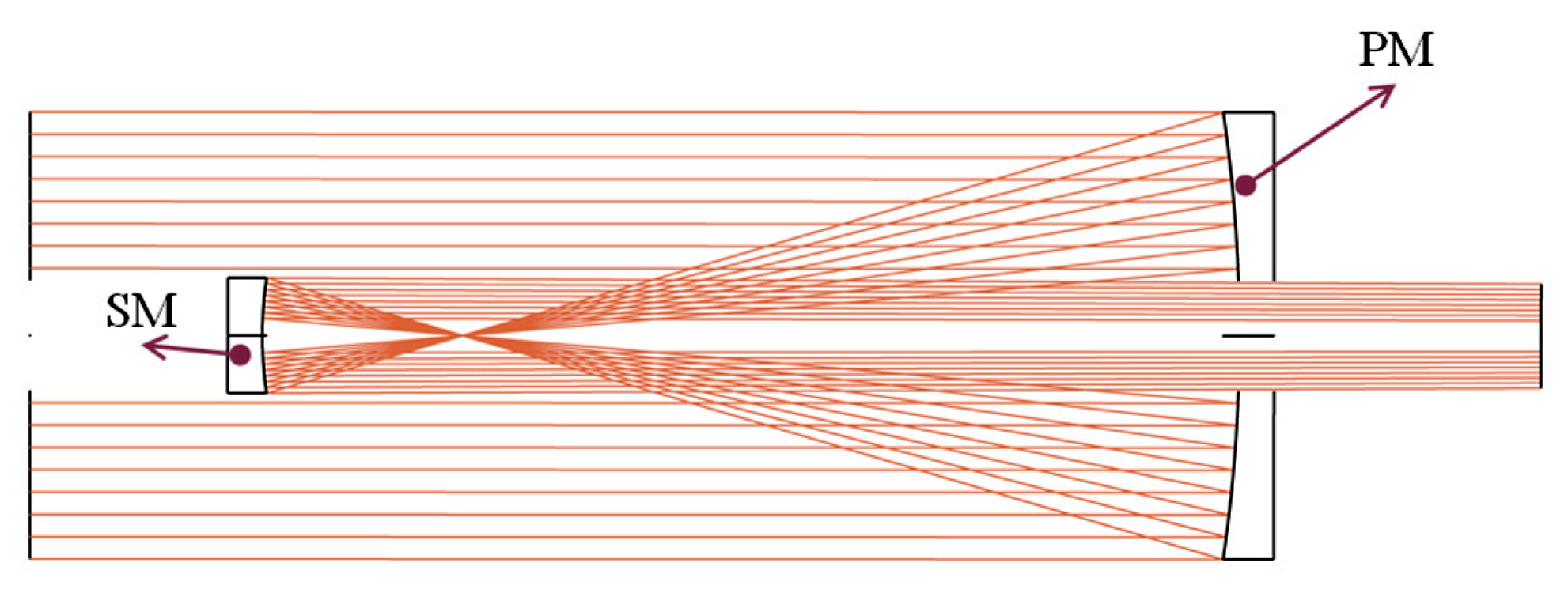
According to the analysis in Section 2.1, the spherical aberration, coma, and astigmatism of the system can be automatically corrected when the PM and SM are both parabolic mirrors. The afocal structure enables “parallel light in, parallel light out”. According to Equations (5) and (6), it can be calculated that the aperture value of the initial coaxial structure is 117.76 mm, the off-axis of the aperture is 30 mm, and the distance between the PM and SM is 280 mm. Compared to refractive structures with the same indicators, the total optical length can be reduced by about 40%. This parameter is determined by the magnification of the telescope system and the curvature of the PM. The layout of the designed OTAOS is shown in Figure 7.
The structure has a real exit pupil, which is convenient to connect the pupil with the subsequent aperture-divided system, and retains enough space for the aperture-divided structure. The whole optical system can be divided into four channels by adding different off-axis structures at the aperture stop of the OTAOS. The four aperture-divided channels should meet the close-contact distribution at the position of the exit pupil, as shown in Figure 4, to facilitate the close-contact state of the first image surface after the aperture-divided system. The exit pupil size of the single-channel telescopic system is 8 mm and is located 60 mm behind the secondary mirror. The wavefront errors of different channels are shown in Figure 8. The outgoing beams have good wavefront properties, and the wavefront aberrations are all less than 0.0866 waves, which is convenient for subsequent matching with the aperture-divided structure.

4.2. Division of the Aperture System and Relay System

The telescope subsystem extends the detection range, while the aperture-divided and relay structures enable simultaneous multi-channel imaging and ensure a match with the detector. According to the technical indicators given in Table 1, the working wavelength of this example is in the MWIR band, and the detector is a cooled detector with a cold stop. During system integration, the aperture-divided module first performs the primary imaging, after which the relay group is added to achieve 100% cold shield efficiency and the object-image conjugation.
(1)
Aperture-divided optical module
An aperture-divided optical module is added at the exit pupil of the off-axis reflective telescope optical system, which is shown in Figure 9a. Each color corresponds to a different field of view. In this case, the aperture-divided optical system consists of four components. According to Equation (9), the decenter value of the aperture-divided system Δ of the aperture-divided group must be more than 0.707 times the aperture diameter D 2 of the aperture-divided group, with each aperture-divided group having a radial decenter value of 6.8 mm.
Specifically, in this case, the aperture-divided optical module is composed of five lenses, which is illustrated in Figure 9b. In different aperture-divided components, the first lens is a polarizer representing different polarization states. The remaining optical modules are made up of four spherical lenses comprising silicon, germanium, and ZnS, which are frequently used optical materials in the infrared range. The last lens is a field lens, which is used for controlling the incidence angle of the primary light incident on the plane of the image, improving the telecentricity and making it easier for the pupil matching with the following optical systems.
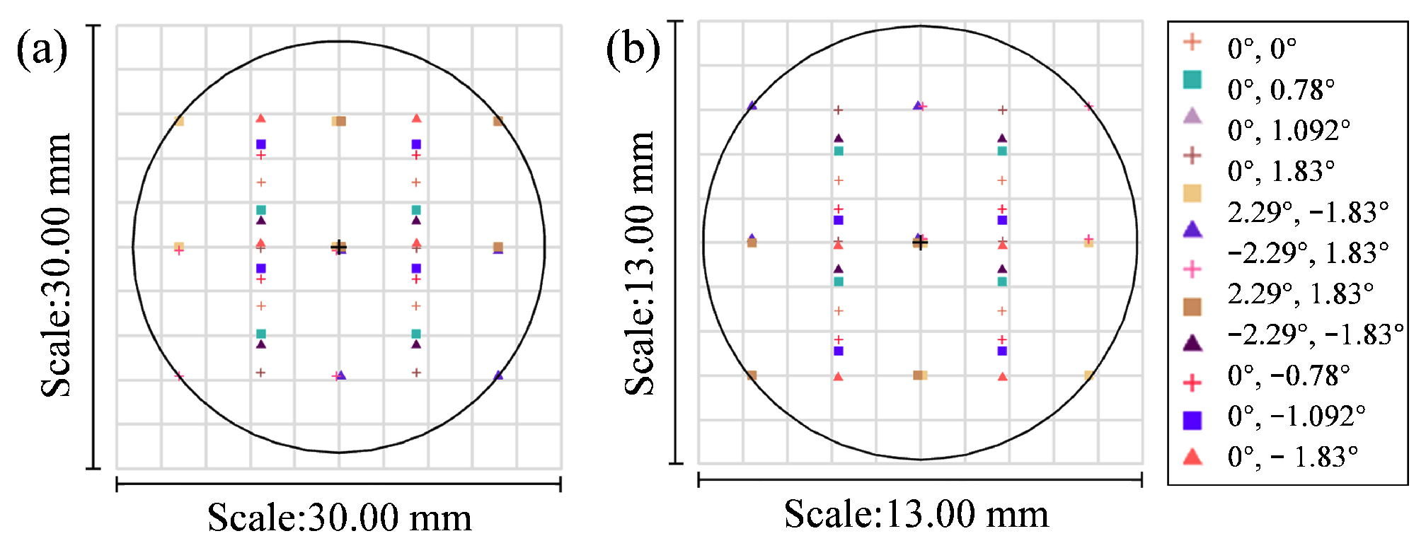
The focus spot of each aperture-divided structure imaging occupies 1/4 of the image plane area, and the image planes under each multiple channel should be closely connected without gaps or overlaps to prevent wasting the field of view. In this example, the diameter of the intermediate image plane is 27 mm, while the image plane distribution of a single sub-aperture channel has a circum-diameter of 13 mm. The size of the lens between channels must be strictly smaller than the image plane size; otherwise, the lenses may obstruct or interfere with each other.
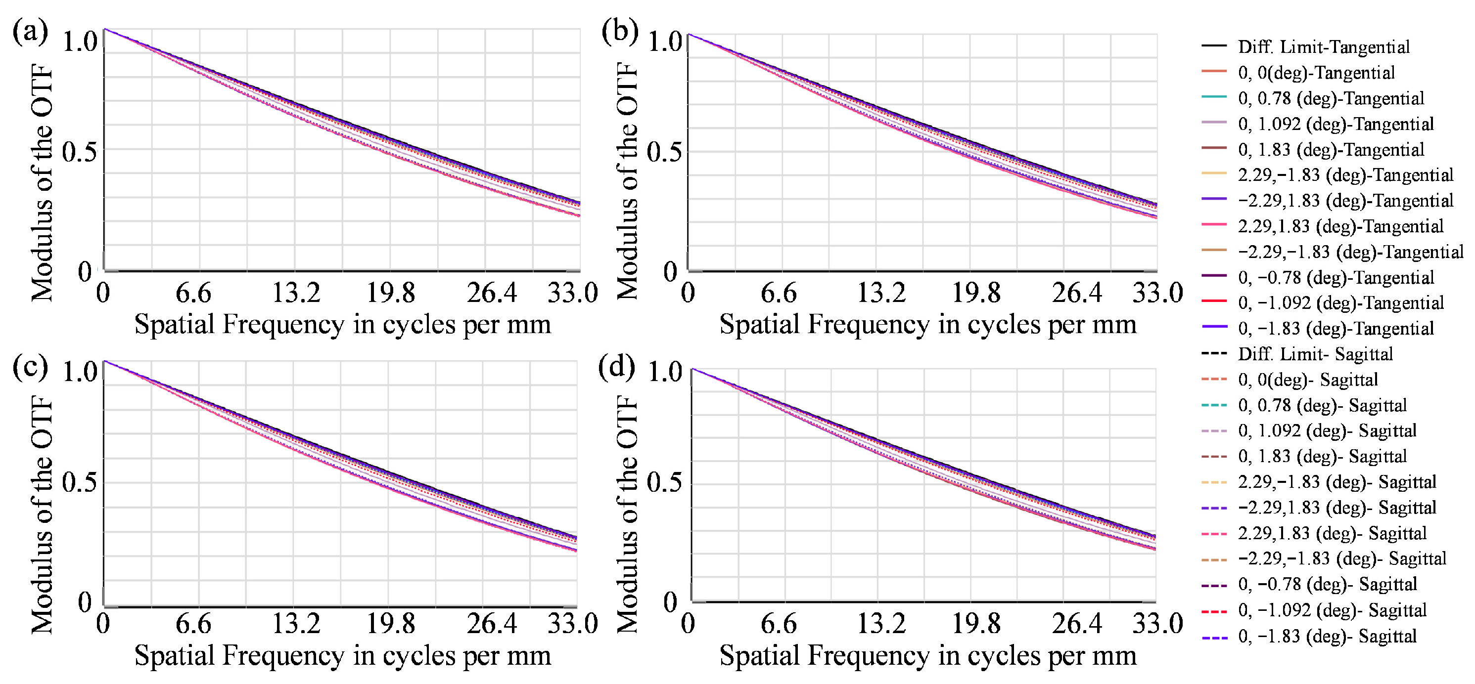
The Modulation Transfer Function (MTF) evaluates the image quality of an optical system, which is the modulus of the Optical Transfer Function (OTF). Finally, the MTF curves of different channels of the designed aperture-divided structure are shown in Figure 10. The tangential direction is shown by the dashed line, and the sagittal direction is shown by the solid line. The diffraction limit is shown by the black line. Each channel is close to the diffraction limit at 33 line pairs per millimeter (lp/mm), and the imaging effect between different channels is consistent.
(2)
Relay lens
To achieve image plane matching of the imaging detector and achieve 100% cold shield efficiency, a relay mirror group needs to be introduced after the aperture-divided module. When designing the relay lens group, the main factors to be considered include the problem of pupil connection, the conjugate relationship between the object plane and image planes, the selection of optical materials, and the balance of aberration. The relay lens group enables object space telecentricity, which is not only conducive to achieving pupil matching with the aperture-divided optical module, but also conducive to achieving 100% cold shield efficiency.

4.3. Design Results

Figure 11 depicts the layout for the whole system, which includes the PM, SM, aperture-divided module, and relay lens group. Different colors represent different fields of view. The detailed surface data and the configuration of the off-axis catadioptric aperture-divided optical system are listed in Table 2. The size of the overall optical structure is only 280 mm (length) × 80 mm (width) × 150 mm (height), with a highly folded layout.
Figure 12 depicts the footprint distribution diagram for the primary and final image planes of the designed aperture-divided optical system. The circle in the black line in Figure 12 represents the outer envelope of different field of view imaging points on the image plane. Different channels can accomplish close contact imaging at the image plane without crosstalk, resulting in high image quality while maximizing image plane usage.
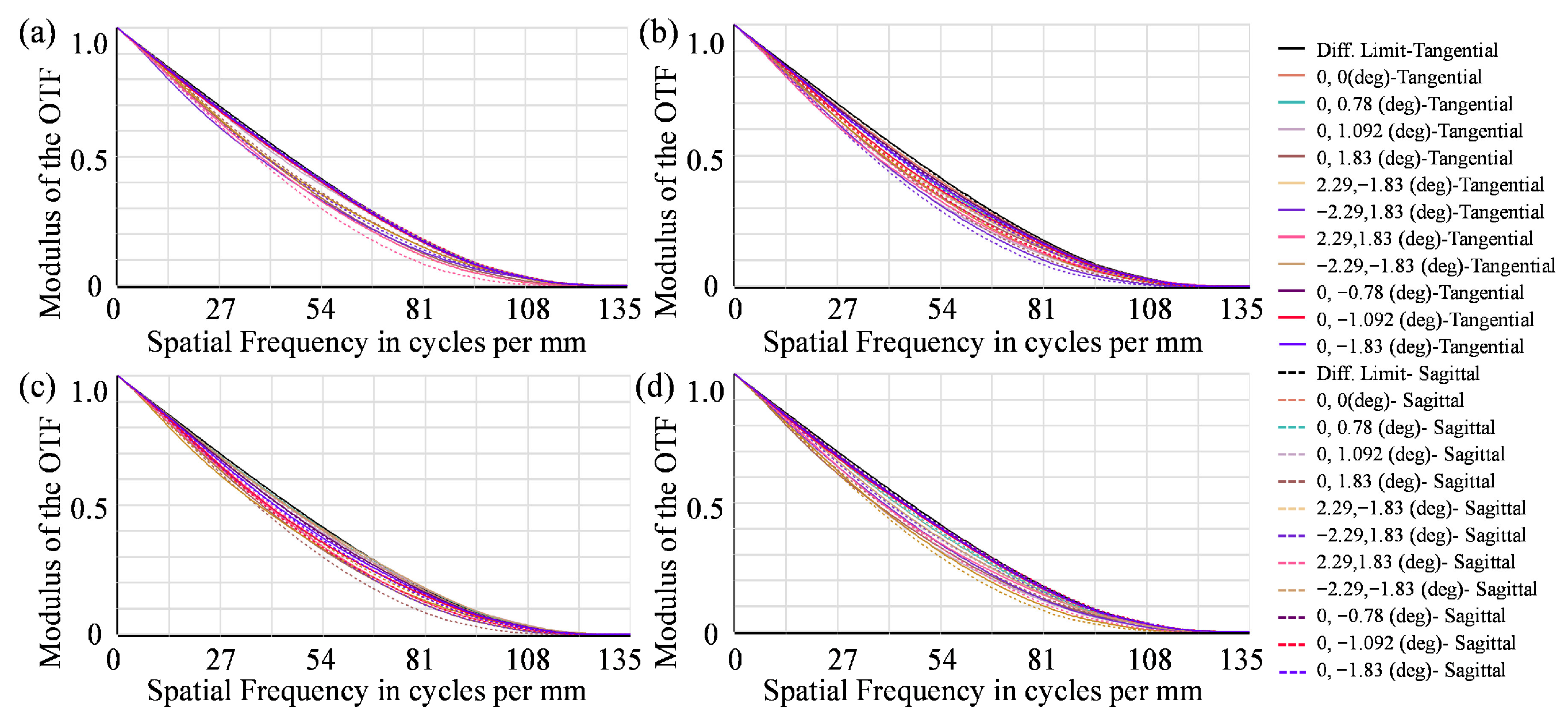
The MTF curves of different aperture-divided channels are shown in Figure 13, which are close to the diffraction limit at the cut-off frequency. According to the Nyquist sampling theorem, the required transfer function frequency that should be observed is 33 lp/mm. The MTF values of different sub-apertures exceed 0.54 at the observation frequency. These results demonstrate that good image quality is achieved.
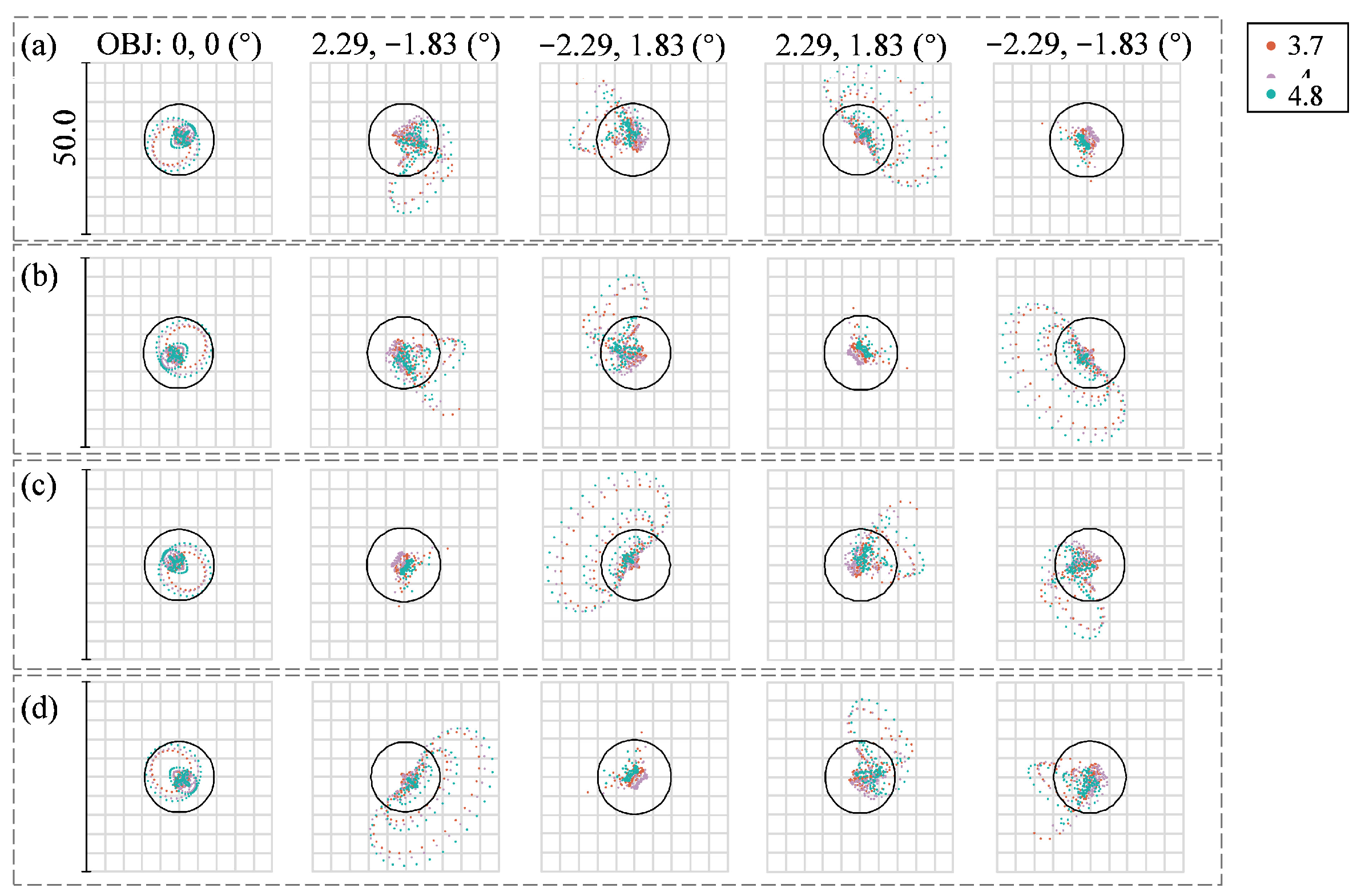
The spot diagrams of different channels with the field of view in object space are presented in Figure 14. The root mean square (RMS) radius of the spot diagrams is much smaller than the Airy disk, which is shown as the circle in the black line. In addition, the average RMS wavefront errors of different sub-aperture systems are less than 0.04 waves. These image quality evaluation metrics collectively demonstrate that the high-order residuals are well controlled.

4.4. Manufacturability Analysis

The optical system’s tolerance is the permissible difference between the system’s structural parameters and the theoretical value during real processing. When setting tolerances, it is vital to consider both the production process and the cost, as well as to create measurement standards. To simulate the effects of the processing and assembly processes on the actual imaging effect, a tolerance analysis of the optical system is performed, which includes optical element tolerance, mechanical assembly tolerance, and material tolerance. The tolerance setting table for the optical system is presented in Table 3. The diffraction MTF is used to assess the performance of an optical system. After 500 Monte Carlo tolerance analyses, the average diffraction MTF of the four aperture-divided channels is 80% likely to be greater than 0.3 at 33 lp/mm. The results show that the tolerance distribution is reasonable and has good machinability.
In the paper, we performed a stray light analysis to identify potential sources and propose mitigation strategies. As shown in Figure 15a, by splitting rays to simulate realistic incident light conditions, the incoherent irradiance distribution on the detector is as illustrated in Figure 15b.
In addition to the target image point distribution, some discrete stray light spots were observed. The following measures were implemented to suppress stray light: Firstly, anti-reflection coatings were applied to optical surfaces, and lens edges were blackened. Secondly, a field stop was placed at the intermediate image plane to block stray radiation. Furthermore, the analysis suggests that adding a baffle with serrated edges would be an effective means to further mitigate out-of-field stray radiation. The final imaging result, shown in Figure 15c, demonstrated a noise-to-peak optical power ratio of less than 10−9, which verified that the proposed design effectively suppressed the influence of stray light.

5. Discussion

This work presents a design method for a catadioptric aperture-divided optical system applied to distant multi-channel imaging. Our research effectively addresses the traditional trade-off between performance and size, paving the way for high-performance, miniaturized simultaneous polarization imagers.
The design methodology proposed in this article avoids the problem of inconsistent targets caused by time-division imaging in traditional polarization imaging [20,21], as well as the system complexity arising from multiple detectors [2,22]. Our approach enables real-time multi-channel imaging of distant targets using a single optical system and detector. The catadioptric aperture optical system achieves a 40% reduction in total length compared to traditional refractive systems [34]. Distinguishing itself from prior studies, our system preserves high optical performance while achieving miniaturization without sacrificing the field of view. Additionally, the system achieves a diffraction-limited MTF and 100% cold shield efficiency. These results demonstrate the effectiveness of the proposed method which combines a reflective telescope structure and refractive aperture-divided structure. A consideration for practical implementation is the system’s sensitivity to alignment errors, necessitating precise manufacturing and assembly.
The proposed off-axis catadioptric aperture-divided design holds promise for simultaneous infrared polarization imaging applications. This research not only provides valuable insights into the design of compact simultaneous polarization systems, but also serves as a reference for the aperture-divided imaging technologies.

6. Conclusions

This study has presented an off-axis catadioptric division of aperture optical system design approach and an MWIR aperture-divided optical system design example to achieve real-time polarization detection of distant objects. First, we calculated the Seidel aberration via ray tracing, and obtained a coaxial reflection initial structure with superior image quality by minimizing the aberration goal function. Second, we optimized an OTAOS with a real exit pupil by adjusting the lens parameters. Finally, we established a correlation between the off-axis aperture value and the system’s optical parameters. This allowed us to develop a cooled infrared optical system capable of detecting multiple polarization states. The designed system demonstrates high image quality, with its MTF curve approaching the diffraction limit at 33 lp/mm. The four-channel optical subsystem enables tight contact imaging on the image plane, achieving 100% cold shield efficiency, and the optimal utilization of the field of view and aperture. The designed aperture-divided infrared optical imaging system provides a valuable reference in the field of multi-channel imaging applications.

Author Contributions

Conceptualization, J.C. and H.X.; methodology, J.C. and T.Y.; software, J.C. and T.Y.; supervision, L.Y. and H.X.; validation, J.C. and T.Y.; formal analysis, J.C.; resources, L.Y. and H.X.; writing—original draft preparation, J.C.; writing—review and editing, J.C., L.Y. and H.X.; visualization, J.C.; project administration, L.Y. and H.X.; funding acquisition, L.Y. All authors have read and agreed to the published version of the manuscript.

Funding

This research received no external funding.

Institutional Review Board Statement

Not applicable for studies not involving humans or animals.

Informed Consent Statement

Not applicable for studies not involving humans.

Data Availability Statement

The data underlying the results presented in this study are not currently publicly available but may be obtained from the corresponding authors upon request.

Conflicts of Interest

The authors declare no conflicts of interest.

References

  1. Cao, J.; Huang, Y.; Wang, J.; Chang, J.; Li, D. Design of dual-channel off-axis reflective foveated imaging optical system with high speed. Opt. Laser Technol. 2025, 182, 112110. [Google Scholar] [CrossRef]
  2. Hubold, M.; Montag, E.; Berlich, R.; Brunner, R.; Brüning, R. Multi-aperture system approach for snapshot multispectral imaging applications. Opt. Express 2021, 29, 7361–7378. [Google Scholar] [CrossRef]
  3. Chen, W.; Zhang, X.; Liu, X.; Fang, F. Optical design and simulation of a compact multi-aperture camera based on a freeform microlens array. Opt. Commun. 2015, 338, 300–306. [Google Scholar] [CrossRef]
  4. Shah, V.; Rachlin, Y.; Shepard, R.H.; Shih, T. Shift-encoded optically multiplexed imaging. Opt. Eng. 2017, 56, 041314. [Google Scholar] [CrossRef]
  5. Chen, Z.; Zhang, C.; Mu, T.; Wang, Y.; He, Y.; Yan, T.; Chen, Z. Coded aperture full-stokes imaging spectropolarimeter. Opt. Laser Technol. 2022, 150, 107946. [Google Scholar] [CrossRef]
  6. Rubin, N.A.; D’Aversa, G.; Chevalier, P.; Shi, Z.J.; Chen, W.T.; Capasso, F. Matrix Fourier optics enables a compact full-Stokes polarization camera. Science 2019, 365, eaax1839. [Google Scholar] [CrossRef] [PubMed]
  7. Rubin, N.A.; Chevalier, P.; Juhl, M.; Tamagnone, M.; Chipman, R.; Capasso, F. Imaging polarimetry through metasurface polarization gratings. Opt. Express 2022, 30, 9389–9412. [Google Scholar] [CrossRef] [PubMed]
  8. Bian, Y.; Jiang, Y.; Huang, Y.; Yang, X.; Deng, W.; Shen, H.; Shen, R.; Kuang, C. Smart-phone phase contrast microscope with a singlet lens and deep learning. Opt. Laser Technol. 2021, 139, 106900. [Google Scholar] [CrossRef]
  9. Qu, Z.; Zhong, X.; Zhang, K.; Wang, Y.; Li, L.; Liu, J.; Zeng, C. Automatic compact-volume design strategy for unobscured reflective optical systems based on conicoid surfaces. Opt. Commun. 2023, 533, 129304. [Google Scholar] [CrossRef]
  10. Liu, J.; Hugot, E.; Muslimov, E.; Lombardo, S. Compact off-axis reflective optical system design combining freeform mirror and freeform detector. Opt. Commun. 2024, 565, 130675. [Google Scholar] [CrossRef]
  11. Rubin, N.A.; Shi, Z.; Capasso, F. Polarization in diffractive optics and metasurfaces. Adv. Opt. Photonics 2021, 13, 836–970. [Google Scholar] [CrossRef]
  12. Li, G.; Li, P.; Chen, T.; Tian, X.; Gao, S.; Yang, Z.; Li, G.; Li, M. Microspherical Lens Assembly for Super-Wide Field of View of Super-Resolution Optical Imaging. In Proceedings of the 2020 IEEE 20th International Conference on Nanotechnology (IEEE-NANO), Virtual, 29–31 July 2020; pp. 168–171. [Google Scholar]
  13. Ning, Y.; Hu, Y.; Cheng, X.; Hao, Q.; Cheng, Y.; Li, T.; Tao, X. Freeform Surface Graded Optimization of Deformable Mirrors in Integrated Zoom and Image Stabilization System Through Vectorial Ray Tracing and Image Point Freezing Method. IEEE Photonics J. 2020, 12, 6900316. [Google Scholar] [CrossRef]
  14. Roche, M.E.; Chenault, D.B.; Vaden, J.P.; Lompado, A.; Voelz, D.; Schulz, T.J.; Givens, R.N.; Gamiz, V.L. Synthetic Aperture Imaging Polarimeter. In Proceedings of the Polarization: Measurement, Analysis, and Remote Sensing IX, Orlando, FL, USA, 5–9 April 2010. [Google Scholar]
  15. Li, S.; Jin, W.Q.; Xia, R.Q.; Li, L.; Wang, X. Radiation correction method for infrared polarization imaging system with front-mounted polarizer. Opt. Express 2016, 24, 26414–26430. [Google Scholar] [CrossRef]
  16. Zhang, Y.; Shi, H.; Jiang, H. Polarization Aberration of a Non-Rotationally Symmetric Optical System with Freeform Surfaces. IEEE Access 2021, 9, 145538–145553. [Google Scholar] [CrossRef]
  17. Tyo, J.S.; Goldstein, D.L.; Chenault, D.B.; Shaw, J.A. Review of passive imaging polarimetry for remote sensing applications. Appl. Opt. 2006, 45, 5453–5469. [Google Scholar] [CrossRef]
  18. Meriaudeau, F.; Ferraton, M.; Stolz, C.; Morel, O.; Bigué, L. Polarization Imaging for Industrial Inspection; SPIE: San Jose, CA, USA, 2008; Volume 6813. [Google Scholar]
  19. Li, X.; Wang, H.; Xu, X.; Ju, L.; Fan, Z.; Chen, S. Mid-infrared full-Stokes polarization detection based on dielectric metasurfaces. Opt. Commun. 2021, 484, 126690. [Google Scholar] [CrossRef]
  20. Gu, N.; Xiao, Y.; Huang, L.; Rao, C. Polarization imaging based on time-integration by a continuous rotating polarizer. Opt. Express 2022, 30, 3497–3515. [Google Scholar] [CrossRef]
  21. Chaturvedi, M.; Bhandare, R.; Kumar, S.; Verma, Y.; Raja, S. A compact full Stokes polarimeter. Optik 2022, 267, 169645. [Google Scholar] [CrossRef]
  22. Mudge, J.; Virgen, M.; Dean, P. Near-Infrared Simultaneous Stokes Imaging Polarimeter; SPIE: San Jose, CA, USA, 2009; Volume 7461. [Google Scholar]
  23. Perkins, R.; Gruev, V. Signal-to-noise analysis of Stokes parameters in division of focal plane polarimeters. Opt. Express 2010, 18, 25815–25824. [Google Scholar] [CrossRef]
  24. Kudenov, M.W.; Pezzaniti, J.L.; Gerhart, G.R. Microbolometer-infrared imaging Stokes polarimeter. Opt. Eng. 2009, 48, 063201. [Google Scholar] [CrossRef]
  25. Yao, D.; Liang, H.; Campos, J.; Yan, L.; Yan, C.; Jiang, C.; Tan, S.; Liang, C.; Wang, H.; Meng, L.; et al. Calculation and restoration of lost spatial information in division-of-focal-plane polarization remote sensing using polarization super-resolution technology. Int. J. Appl. Earth Obs. Geoinf. 2023, 116, 103155. [Google Scholar] [CrossRef]
  26. Zhang, W.F.; Liang, J.; Ren, L.Y.; Ju, H.J.; Qu, E.S.; Bai, Z.F.; Tang, Y.; Wu, Z.X. Real-time image haze removal using an aperture-division polarimetric camera. Appl. Opt. 2017, 56, 942–947. [Google Scholar] [CrossRef]
  27. Moultrie, S.; Roche, M.; Lompado, A.; Chenault, D. Design of a dual use imager incorporating polarimetric capabilities—Art. no. 66820B. In Proceedings of the Conference on Polarization Science and Remote Sensing III, San Diego, CA, USA, 29–30 August 2007; p. B6820. [Google Scholar]
  28. Mu, T.K.; Zhang, C.M.; Liang, R.G. Demonstration of a snapshot full-Stokes division-of-aperture imaging polarimeter using Wollaston prism array. J. Opt. 2015, 17, 8. [Google Scholar] [CrossRef]
  29. Mu, T.K.; Bao, D.H.; Han, F.; Sun, Y.Y.; Chen, Z.Y.; Tang, Q.; Zhang, C.M. Optimized design, calibration, and validation of an achromatic snapshot full-Stokes imaging polarimeter. Opt. Express 2019, 27, 23009–23028. [Google Scholar] [CrossRef] [PubMed]
  30. Du, W.C.; Jia, W.G.; Zhang, Z.J.; Wang, C.S. Optimization of the Infrared Stokes Imaging Polarimeter. In Proceedings of the Annual Conference of the Chinese-Society-for-Optical-Engineering (CSOE) on Applied Optics and Photonics China (AOPC)—Optical Spectroscopy and Imaging, Beijing, China, 4–6 June 2017. [Google Scholar]
  31. Pezzaniti, J.L.; Chenault, D.B. A Division of Aperture MWIR Imaging Polarimeter. In Proceedings of the Conference on Polarization Science and Remote Sensing II, 20050802-04. San Diego, CA, USA, 31 July–4 August 2005. [Google Scholar]
  32. He, H.; Ji, Y.; Shen, W. Polarization aberration of optical systems in imaging polarimetry. Chin. Opt. Lett. 2012, 10, S11102. [Google Scholar] [CrossRef]
  33. Mu, T.K.; Zhang, C.M.; Li, Q.W.; Liang, R.G. Error analysis of single-snapshot full-Stokes division-of-aperture imaging polarimeters. Opt. Express 2015, 23, 10822–10835. [Google Scholar] [CrossRef]
  34. Wang, X.; Wang, F.; Xu, R.; Liu, X.; Yuan, H. Design of Hyperspectral Polarization Imaging System with Multiple Simultaneous Apertures Based on Orthogonal Dual-Polarization. Laser Optoelectron. Prog. 2018, 55, 031104. [Google Scholar] [CrossRef]
  35. Su, Y.; Xie, H.; Wang, Y.; Yang, L. Design of aperture-divided multispectral imaging system in mid-infrared band. J. Appl. Opt. 2018, 39, 767–772. [Google Scholar] [CrossRef]
  36. Cook, L.G. Three Mirror Anastigmatic Optical System. U.S. Patent US4265510A, 5 May 1981. [Google Scholar]
  37. Meng, Q.; Wang, D.; Wang, X.; Li, W.; Yang, X.; Yan, D.; Li, Y.; Cao, Z.; Ji, Q.; Sun, T.; et al. High Resolution Imaging Camera (HiRIC) on China’s First Mars Exploration Tianwen-1 Mission. Space Sci. Rev. 2021, 217, 42. [Google Scholar] [CrossRef]
  38. Korsch, D. Reflective Optics; Academic Press: San Diego, CA, USA, 1991; pp. 207–213. [Google Scholar]
  39. Liu, R.; Li, Z.; Duan, Y.; Fang, F. A Design for a Manufacturing-Constrained Off-Axis Four-Mirror Reflective System. Appl. Sci. 2020, 10, 5387. [Google Scholar] [CrossRef]
  40. Geary, J.M. Introduction to Lens Design: With Practical ZEMAX Examples; Willmann-Bell: Richmond, VA, USA, 2002. [Google Scholar]
  41. Welford, W.T. Aberrations of Optical Systems, 1st ed.; Routledge: New York, USA, 1986. [Google Scholar]
  42. Wu, Y.; Wang, L.-p.; Yu, J.; Zhang, X.; Jin, C.-s. Design of off-axis multi-reflective optical system based on particle swarm optimization. Chin. Opt. 2021, 14, 1435–1450. [Google Scholar] [CrossRef]
  43. Hudson, R.D. Infrared System Engineering; Wiley: Hoboken, NJ, USA, 1969. [Google Scholar]
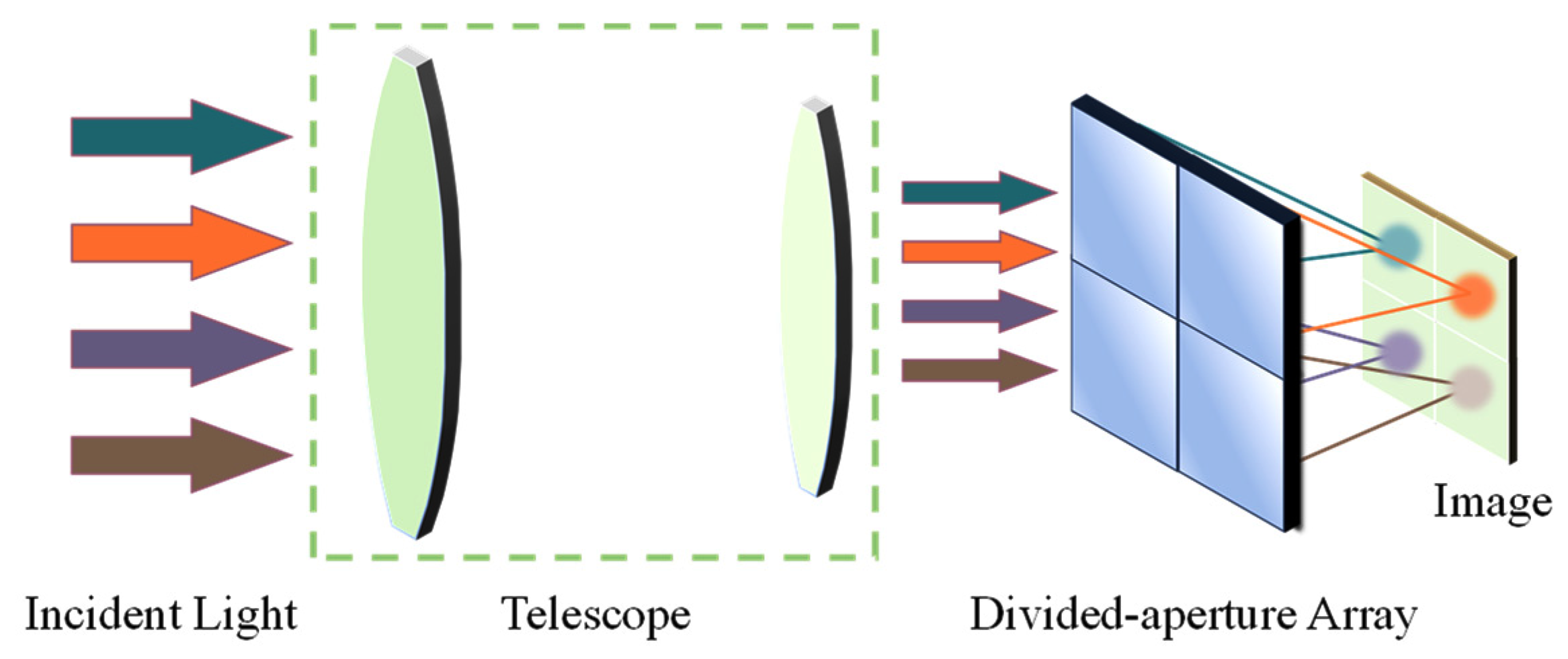
Figure 1. The concept design of the aperture-divided optical system.
Photonics 12 01008 g001
Figure 2. Layout of the light path of two telescopic structures. (a) Kepler structure; (b) Galilean structure.
Photonics 12 01008 g002
Figure 3. Schematic diagram of the aperture-divided optical system.
Photonics 12 01008 g003
Figure 4. Layout of the aperture-divided structure.
Photonics 12 01008 g004
Figure 5. Relationship between detection distance and focal length of the optical system.
Photonics 12 01008 g005
Figure 6. Coaxial reflection initial structure.
Photonics 12 01008 g006
Figure 7. Layout of the OTAOS.
Photonics 12 01008 g007
Figure 8. The wavefront diagram of the afocal telescopic system. (a) represents the aperture-divided with eccentricity (+x, +y), (b) represents the aperture-divided with eccentricity (+x, −y), (c) represents the aperture-divided with eccentricity (−x, +y), and (d) represents the aperture-divided with eccentricity (−x, −y).
Photonics 12 01008 g008
Figure 9. Schematic diagram of the optical structure with a divided aperture. (a) The layout of the whole structure, (b) the layout of the aperture-divided module.
Photonics 12 01008 g009
Figure 10. MTF curves of the intermediate image plane with different aperture-divided structures. (a) represents the aperture-divided with eccentricity (+x, +y), (b) represents the aperture-divided with eccentricity (+x, −y), (c) represents the aperture-divided with eccentricity (−x, +y), and (d) represents the aperture-divided with eccentricity (−x, −y).
Photonics 12 01008 g010
Figure 11. Layout of the whole off-axis catadioptric aperture-divided optical system.
Photonics 12 01008 g011
Figure 12. Footprint diagrams of (a) the intermediate image plane and (b) the final image plane.
Photonics 12 01008 g012
Figure 13. MTF curves of off-axis aperture-divided optical systems with different channels. (a) represents the aperture-divided with eccentricity (+x, +y), (b) represents the aperture-divided with eccentricity (+x, −y), (c) represents the aperture-divided with eccentricity (−x, +y), and (d) represents the aperture-divided with eccentricity (−x, −y).
Photonics 12 01008 g013
Figure 14. Spot diagram of off-axis aperture-divided optical systems with different channels. (a) represents the aperture-divided with eccentricity (+x, +y), (b) represents the aperture-divided with eccentricity (+x, −y), (c) represents the aperture-divided with eccentricity (−x, +y), and (d) represents the aperture-divided with eccentricity (−x, −y).
Photonics 12 01008 g014
Figure 15. Stray light analysis results. (a) Optical layout. (b) Initial inherent radiance. (c) Final inherent radiance.
Photonics 12 01008 g015
Table 1. Technical indicators of the design case.
ParameterValue
Focal length of the aperture-divided system60 mm
Entrance pupil diameter30 mm
Wavelength3.7–4.8 μm
Pixel number640 × 512
Pixel size15 μm
Table 2. Structural parameters of the off-axis catadioptric aperture-divided optical system.
MaterialRadius (mm)ConicDecenter X (mm)Decenter Y (mm)
The afocal telescopic systemPMmirror−449.59−10−80
SMmirror114.11−10−20.34
The aperture-divided lens group MaterialRadius (mm)
PolarizerSILICONInfinity
Infinity
Lens1SILICON1.331
18.43
Lens2GERMANIUM34.67
10.92
Lens3ZNS24.86
−31.24
Lens4GERMANIUM−406.83
−61.10
The realy lens MaterialRadius(mm)ConicAspheric Surface
High-order Term
4th6th8th
Lens5IRG20446.04
160.38
Lens6IRG105−42.90
−58.50
Lens7GERMANIUM−19.95−1−5.22 × 10⁻⁵−8.17 × 10⁻⁸−1.23 × 10⁻¹⁰
−52.96
Lens8SILICON−163.44−1−8.24 × 10−67.68 × 10−9−2.97 × 10⁻¹²
−28.99
Table 3. Tolerance values.
Tolerance TypesValue
Radius (fringe)2
Thickness (mm)±0.02
Surface irregularity (fringe)0.5
Surface decenter (mm)±0.02
Surface tilt (°)±0.033
Element decenter (mm)±0.02
Element tilt (°)±0.033°
Refractive index±0.001
Abbe number (%)±0.8
Surface error of the PM and SM (μm)PV < 0.5
Disclaimer/Publisher’s Note: The statements, opinions and data contained in all publications are solely those of the individual author(s) and contributor(s) and not of MDPI and/or the editor(s). MDPI and/or the editor(s) disclaim responsibility for any injury to people or property resulting from any ideas, methods, instructions or products referred to in the content.