Article

High-Stability PGC-EKF Demodulation Algorithm Integrated with a Phase Delay Compensation Module

1
State Grid Anhui Electrical Power Research Institute, Hefei 230000, China
2
Key Laboratory of Specialty Fiber Optics and Optical Access Networks, Shanghai University, Shanghai 200444, China
*
Author to whom correspondence should be addressed.
Photonics 2025, 12(1), 44; https://doi.org/10.3390/photonics12010044
Submission received: 30 November 2024 / Revised: 26 December 2024 / Accepted: 2 January 2025 / Published: 6 January 2025
(This article belongs to the Special Issue Advanced Optical Fiber Sensors for Harsh Environment Applications)

Abstract

:
To effectively eliminate the nonlinear distortion caused by the modulation depth (C value) drift and carrier phase delay (θ) in the phase-generated carrier (PGC) demodulation scheme, the PGC-PDC-EKF joint algorithm is presented, which combines phase delay compensation (PDC) with an extended Kalman filter (EKF). The θ is accurately extracted and compensated by the PDC module. Furthermore, with the EKF algorithm, the harmonic distortion of the demodulated signal due to the fluctuation of C value is suppressed. The experimental results indicate that θ is compensated accurately with a resolution of 0.01745 rad. The signal-to-noise and distortion ratio (SINAD) of the improved scheme reaches 54.01 dB, which is 18.03 dB higher than the PGC-Arctan algorithm on average. The total harmonic distortion (THD) is as low as −62.28 dB, which is 26.04 dB lower than the PGC-Arctan algorithm. The linearity of the demodulation system exceeds 99.99%. The proposed method provides a significant reference for demodulation schemes of interferometric fiber optic sensing systems in practical applications.

1. Introduction

The phase-generated carrier (PGC) demodulation method has been widely applied in fiber optic hydrophones, fiber optic seismometers, and fiber optic accelerometers, due to its simple optical path structure, large dynamic range, high resolution, and good linearity [1,2,3,4]. The basic PGC demodulation techniques consist of PGC differential cross multiplication (DCM) and PGC arctangent (Arctan), which usually operate at a certain phase modulation depth (C value) [5,6]. The C value is correlated with the refractive index of the fiber, the optical path difference (OPD) of the interferometer, and the amplitude of the carrier modulation signal. In practical applications, the OPD is affected by external environmental factors, which results in the C value deviating from the optimal value. There is an initial phase delay (θ) in the carrier term of the interference signal due to the long-distance transmission of the signal and the time delay of the optoelectronic conversion device [7,8]. Considering the presence of C value fluctuations and phase delay in the system, the performance of both algorithms decreases, and the demodulation results suffer from nonlinear distortions.
Different improved PGC schemes have been developed to mitigate the effects of the C value or θ. Volkov et al. used an integral control feedback technique to correct the C value, which stabilized the C value at a predefined optimal value [9]. Gong et al. utilized multiple high-frequency harmonic components to directly eliminate the C value, which avoids the influence of the C value on the demodulation result [10]. Although these algorithms eliminate nonlinearity due to the C value drift, the effect of θ is neglected. Zhang et al. made the carrier synchronize with the interference signal by maximizing the output amplitudes of lowpass filters [11]. Nikitenko et al. employed two pairs of reference carriers to establish the orthogonal components, compensating for all possible phase delays without using a phase compensator [12]. Despite the suppression of nonlinear distortion by these algorithms, the performance of the algorithms deteriorates when both C value drift and θ are present in the system. Furthermore, the calculation of the C value is inaccurate when θ is not equal to kπ in the system [13]. Therefore, the demodulation results are more accurate when both the C value and θ are considered in the system. Xie et al. proposed a nonlinear error compensation method by calculating the C value and θ [14]. It involves complex calculations and consumes substantial hardware resources. Hou et al. proposed the ellipse fitting algorithm (EFA) based on the extended Kalman filter (EKF), which is effective in suppressing the nonlinear distortion caused by C value drift [15]. Nevertheless, the EFA proves ineffective when θ approaches kπ/4 [16,17]. Therefore, designing a highly stable demodulation algorithm is necessary to eliminate nonlinear distortion during the signal processing of fiber optic sensors.
In this work, an improved PGC-Arctan demodulation scheme combining phase delay compensation (PDC) and EKF is proposed, which eliminates the nonlinear distortion caused by C value drift and θ. The PDC module has the merits of fast calculation and high accuracy, which calculates θ by adjusting the compensation phase introduced into the carriers. The harmonic distortion caused by C value fluctuation is suppressed by the EKF module, which improves the stability of the system. Simulation and experiment validate the feasibility of the proposed PGC-PDC-EKF by comparing the performance with the basic PGC-Arctan algorithm and other improved algorithms. As a result, the proposed scheme has good prospects for application in the demodulation of fiber optical sensor signals.

2. Theory

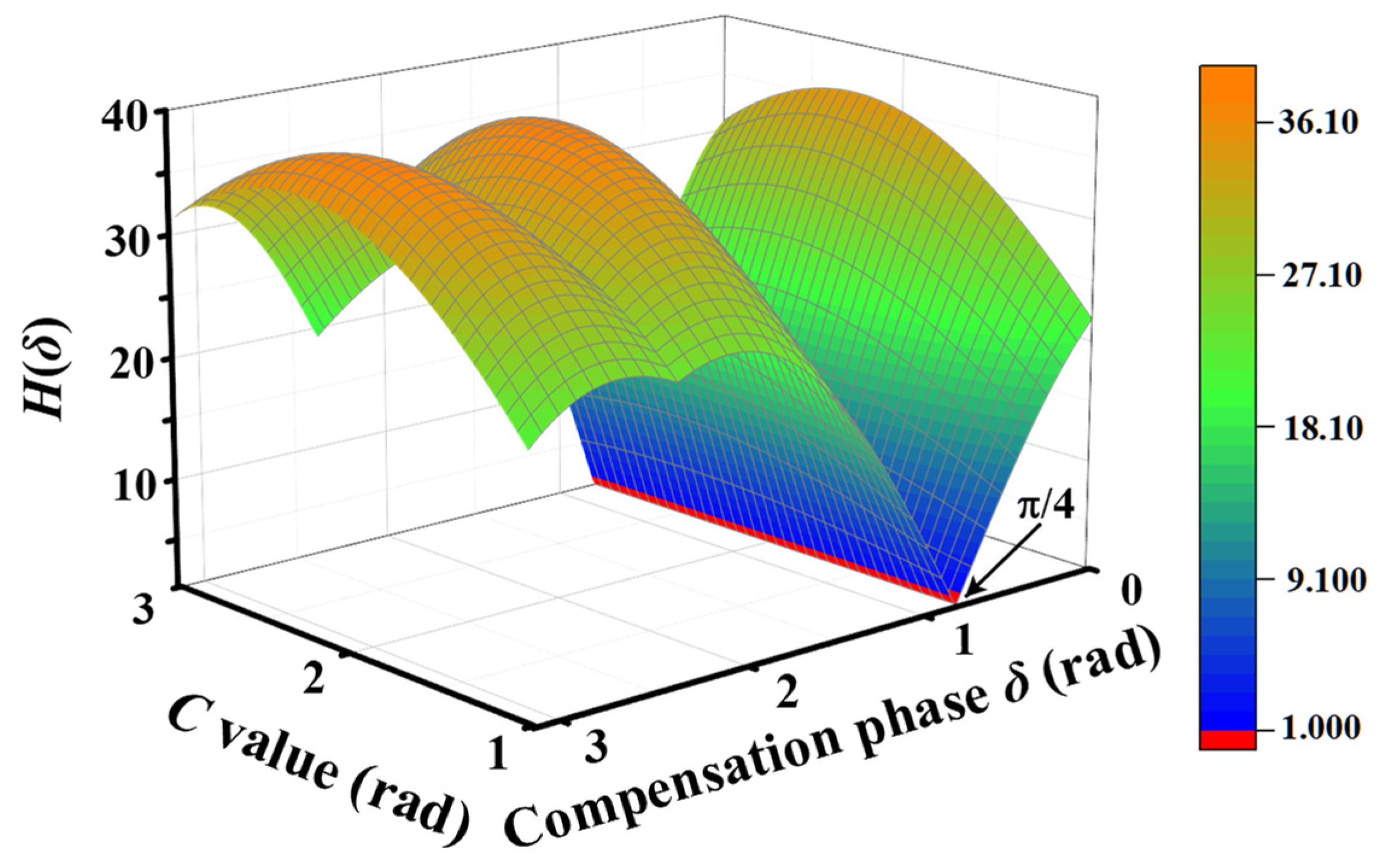
2.1. The Influence of C Value and θ on the Demodulation Result

The flow graph of the basic PGC-Arctan scheme is shown in Figure 1.
The light intensity at the output of the sinusoidal phase modulation interferometer (SPMI) can be expressed as follows:
I t = A 0 + B 0 cos C cos ω c t + θ + φ t ,
where A0 is the direct-current (DC) component, and B0 is the amplitude of the alternating current (AC) component of the interference signal. ωc is the angular frequency of the carrier, and θ is carrier phase delay, which ranges from 0 to 2π. φ(t) represents the measured phase signal.
Fundamental and second-harmonic cosine carriers are introduced to mix with the I(t). The mixing-frequency signals are filtered by a low-pass filter (LPF) to eliminate high-frequency carrier components. Then, a pair of filtered signals can be described as follows:
P 1 = LPF I t cos ω c t = B J 1 C cos θ sin φ t ,
P 2 = LPF I t cos 2 ω c t = B J 2 C cos 2 θ cos φ t ,
where Jn(C) is the nth-order Bessel function of the first kind.
The filtered signals are processed by division and arctangent, and the demodulated signal φ(t) is obtained as follows:
φ t = arctan P 1 / P 2 = arctan J 1 C cos θ J 2 C cos 2 θ tan φ t , = arctan M tan φ t
where M = J1(C)cosθ/J2(C)cos2θ, which is determined by the C value and θ together. If C ≠ 2.63 rad or θ ≠ 0, the coefficient M is not equal to 1, resulting in nonlinear errors in the demodulated signal. Furthermore, if the θ is close to the phase singularities of kπ/4 (k = 1,2,3,6), the phase signal φ(t) cannot be recovered correctly.

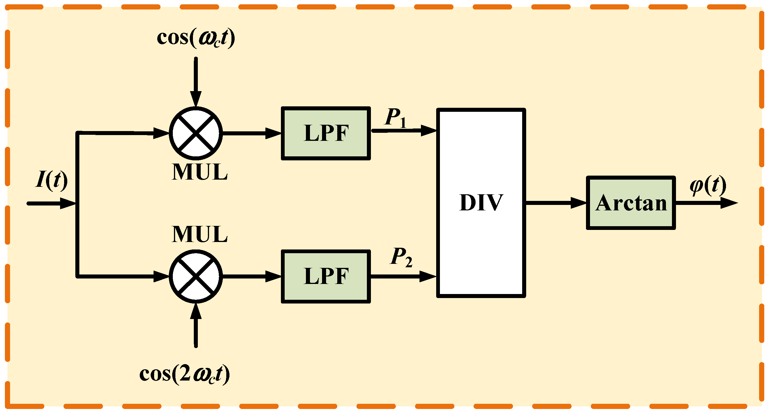
2.2. The Principle of PGC-PDC-EKF Demodulation Scheme

The schematic diagram of the proposed PGC-PDC-EKF improvement scheme is demonstrated in Figure 2. The θ is calculated and compensated by the PDC module, which eliminates the influence of θ on the demodulated signals. With the EKF module, the nonlinear distortion caused by C value drift is suppressed by normalizing the amplitude of filtered signals I1 and I2. Ultimately, the phase signal is precisely demodulated by the Arctan algorithm.
To extract the θ from the interference signal, a compensation phase δ is introduced in DDS1. The mixing-frequency signals S1 and S2 can be obtained from the I(t) multiplied by reference signals sin(ωct + δ) and sin2(ωct + δ) generated by DDS1, which can be expressed as follows:
S 1 = I t sin ω c t + δ ,
S 2 = I t sin 2 ω c t + δ .
The δ is adjusted from 0 to π with a step size of l at the time intervals of a fundamental carrier cycle (Tc). Considering the boundary effect of the LPF, the LPF takes a long time to re-converge after each adjustment of the δ [18,19]. With a narrow (almost 0 Hz) passband, the integration or average operation could be carried out as the exclusive LPF, eliminating the high-frequency carrier components of the interference signal [12]. The signals L1 (n) and L2 (n) are the integral of S1 and S2, respectively, can be expressed as follows:
L 1 n = ( n 1 ) T c n T c S 1 d t = B 0 J 1 C sin θ δ ( n 1 ) T c   n T c sin φ t d t , = R 1 sin θ δ
L 2 n = ( n 1 ) T c   n T c S 2 d t = B 0 J 2 C sin 2 θ δ ( n 1 ) T c n T c cos φ t d t , = R 2 sin 2 θ δ
where n = 1, 2, 3, …, π/l. R 1 = B 0 J 1 C ( n 1 ) T c   n T c sin φ t d t and R 2 = B 0 J 2 C ( n 1 ) T c n T c cos φ t d t are constant coefficients. The values of L1 (n) and L2 (n)are considered as functions of δ. Combining Equations (7) and (8), the objective function H(δ) can be expressed as follows:
H δ = L 1 n + L 2 n = R 1 sin θ δ + R 2 sin 2 θ δ .
The extracted phase delay δx should be determined by calculating the minimum value of the objective function, which can be described as follows:
H δ x = M I N H δ .
The minimum value of the H(δ) is obtained by successive approximation. Combining the ranges of θ and δ, the objective function is the minimum value when δx = θ or δx = θ + π. The demodulated signal of φ(t) experiences a phase inversion if the δx differs from the actual phase delay by π. This phenomenon has no bearing on the demodulation of an individual sensor [12].
With the extracted phase delay δx, the new reference carrier signal cos(ωct + δx) and cos2(ωct + δx) are generated by DDS2, which guarantees the synchronization between the harmonic components of I(t) and cosine carrier signal. The cosine carriers are mixed with the I(t). Then, a pair of non-strictly orthogonal components without carrier phase delay after low-pass filtering can be described as follows:
I 1 t = LPF I t cos ω c t + δ x = B 0 J 1 C cos θ δ x sin φ t , = B 0 J 1 C sin φ t
I 2 t = LPF I t cos 2 ω c t + δ x = B 0 J 2 C cos 2 θ δ x cos φ t . = B 0 J 2 C cos φ t
Considering the C value drift and the non-ideal performance of the LPF in practical applications [20], the I1 (t) and I2 (t) can be rewritten as follows:
I 1 t = h x a x sin φ t I 2 t = k x b x cos φ t ,
where ax and bx are the AC amplitudes. hx and kx are the DC offsets of I1 (t) and I2 (t). According to sin2φ (t) + cos2φ (t) = 1, Equation (13) can be rewritten as follows:
I 1 2 + a x 2 b x 2 I 2 2 2 h x I 1 2 a x 2 k x b x 2 I 2 + h x 2 + a x 2 k x 2 b x 2 a x 2 = 0 .
To correct non-strictly orthogonal signals into strictly orthogonal signals, the EFA is presented in the PGC demodulation technique. Replacing I1 (t) and I2 (t) with x and y, the elliptic equation can be written as follows:
x 2 + E y 2 + F x + G y + H = 0 .
Comparing Equations (14) and (15) can obtain the elliptic parameters E, F, G, and H:
E = a x 2 b x 2 F = 2 h x G = 2 a x 2 k x b x 2 H = h x 2 + a x 2 b x 2 k x 2 a x 2 .
The EKF scheme [15] based on EFA is used to estimate the elliptic parameters E, F, G, and H. The parameters hx, kx, ax, and bx can be obtained by Equation (16):
h x = F / 2 k x = G / 2 E a x = F 2 / 4 + G 2 / 4 E H b x = E F 2 + G 2 4 E H / 2 E .
The two orthogonal signals can be obtained from Equations (13) and (16):
I 1 t = sin φ t = h x I 1 t / a x I 2 t = cos φ t = k x I 2 t / b x .
Ultimately, the φ (t) can be demodulated by the following:
φ t = arctan I 1 t / I 2 t .

3. Simulation and Analysis

In numerical simulation, a simulated SPMI signal is generated, and the signal processing is carried out to obtain the measured phase signal for performance analysis. The parameters are set as follows: the DC and AC components of the interference signal are set to 1 V and 4 V, respectively. The sampling frequency in the system is set as 500 kHz, and the frequency of the modulation carrier is 31.25 kHz. The phase signal φ (t) is simulated by a sinusoidal signal with an amplitude of 1 rad and a frequency of 1 kHz.

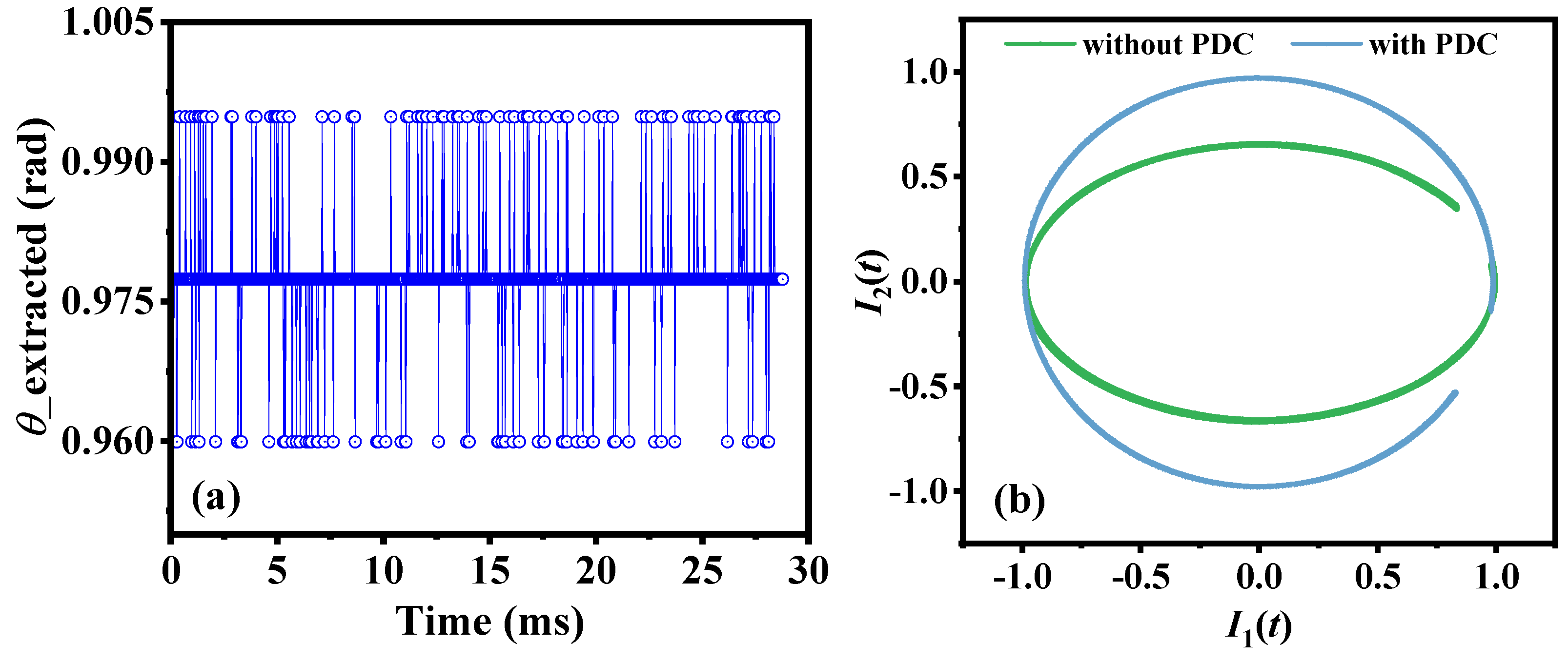
3.1. Performance Analysis of the PDC Module

The θ is adjusted to π/4 rad to analyze the impact of C value drifts on the PDC module. With the C value increased at the steps of π/90 rad, the relationship between the objective function H(δ) and the C value is depicted in Figure 3. The minimum value of H (δ) is consistently located at the compensation phase of π/4 rad (red line), which is the calculated value δx of phase delay. The process of the phase delay calculation is not affected by changes in the C value, which reflects the insensitivity of the PDC algorithm to C value drifts.
To further explore the correlation between step size l and the phase delay calculation results, the step sizes are set to π/45, π/90, π/180, and π/360 rad, respectively. The calculated results δx, error, resolution, and calculation time of the phase delay at different step sizes are summarized in Table 1. As the selected step size l decreases, the error of the calculated δx decreases, which means that the calculation result of phase delay is accurate. Moreover, as the resolution of the phase delay calculation decreases, the calculation time increases. Although a step size of π/360 rad provides the optimal resolution, the computational time is the longest. The computational accuracy is improved at the cost of computational time. Therefore, to strike a balance between resolution and associated computational time, π/180 rad is determined as the optimal compromise.

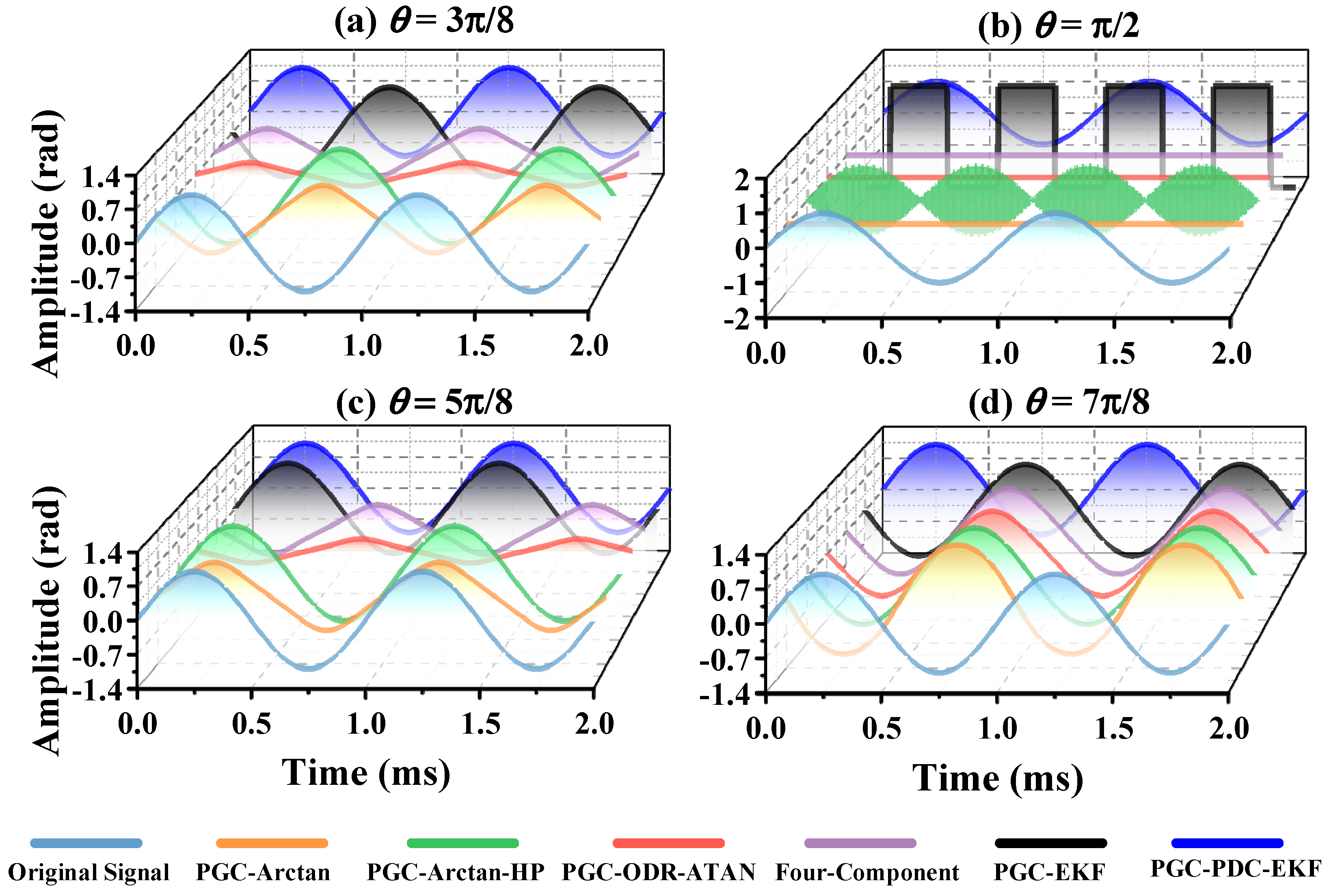
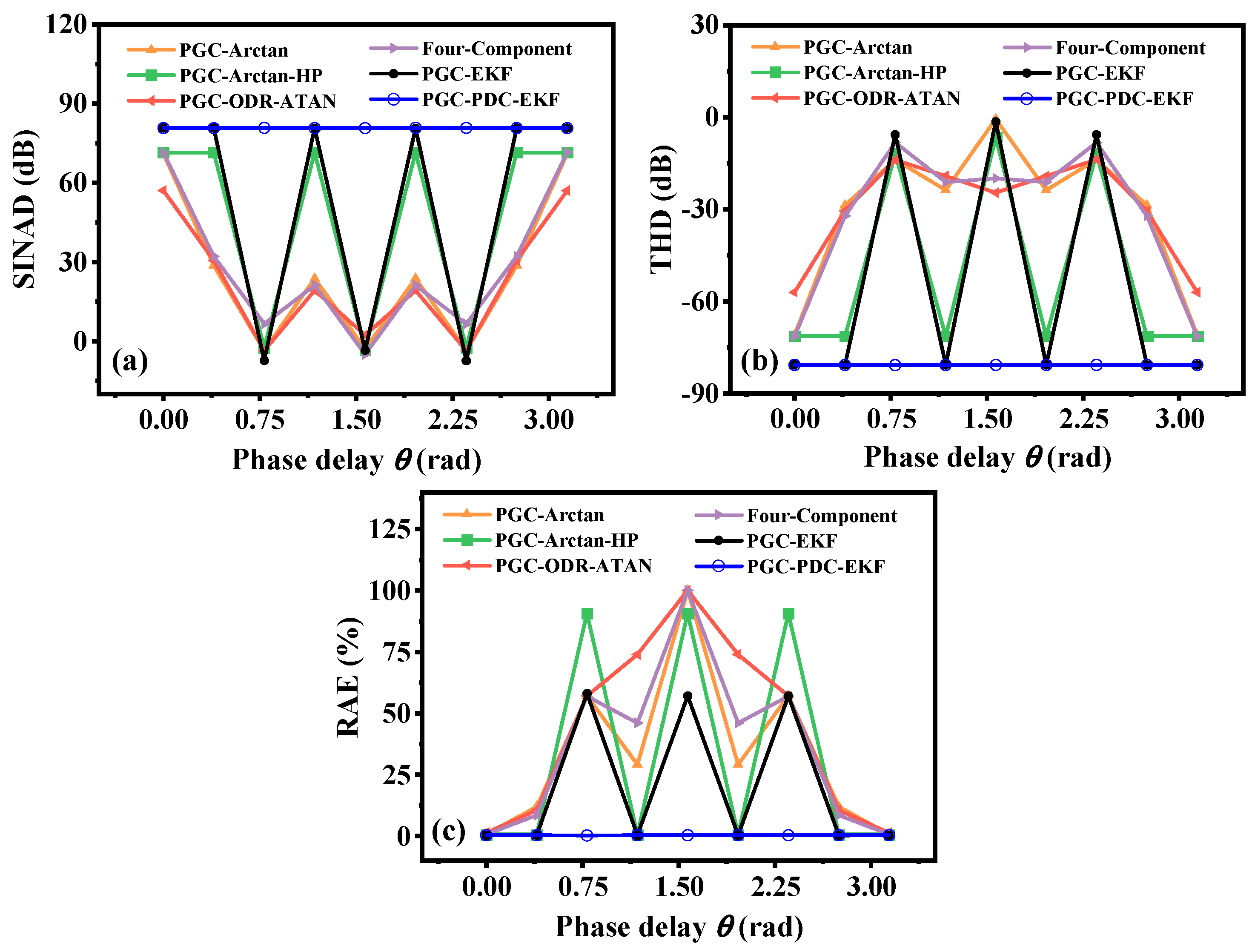
3.2. Performance Comparison of Demodulation Algorithms at Different Phase Delays

Comparison experiments are set up to validate and evaluate the performance of the proposed PGC-PDC-EKF scheme. PGC-PDC-EKF is compared with some traditional and recent demodulation algorithms, including PGC-Arctan [5], PGC-Arctan-HP [21], PGC-ODR-ATAN [22], Four-Component [10], PGC-EKF [23] algorithms.
The performance is measured by three parameters, i.e., signal-to-noise and distortion ratio (SINAD), total harmonic distortion (THD), and relative amplitude error (RAE). When SINAD is larger, THD is smaller, and RAE is close to 0, the similarity between the demodulated signal and the original signal is higher.
SINAD is a measure of signal quality in electronic devices. It represents the ratio of the power of the signal to the combined power of noise and distortion present in the signal, which can be represented as follows:
SIN AD = 10 lg P s P n + P d ,
where Ps is the fundamental power of the signal, Pn denotes the total power of noise, and ∑Pd is the total power of all high-frequency harmonics.
The harmonic distortion, which refers to the additional harmonic components in the output signal compared to the input signal, is caused by the incomplete linearity of the system. THD is the ratio of the total sum of harmonic components in a signal to the amplitude of the fundamental frequency, which can be expressed as follows:
THD = 20 lg A d 2 A s ,
where As is the amplitude of the fundamental frequency component, and Ad is the amplitude of each harmonic component.
The RAE of a demodulated signal is the degree of linear distortion between the amplitude of the output signal and the input signal, which can be represented as follows:
RAE = A o u t A i n A i n 100 % ,
where Aout is the actual measured amplitude of the demodulated signal, and Ain is the amplitude of the input signal.
The demodulated signal waveforms with carrier phase delays in the range of 0 to π are shown in Figure 4. When the phase delay is equal to 3π/8, 5π/8 or 7π/8, nonlinear distortion is observed in the demodulated signal waveforms of PGC-Arctan, PGC-ODR-ATAN and Four-Component schemes. Note that all algorithms except for the proposed PGC-PDC-EKF have problems demodulating the phase signal if the phase delays are phase singularities of π/2. This is mainly because of two reasons, (1) if the phase delay is π/4 or 3π/4, the filtered signal P2 in Equation (3) approaches 0, and the coefficient M in Equation (4) approaches infinity; (2) if the phase delay is π/2 or 3π/2, the filtered signal P1 in Equation (2) approaches 0, and the coefficient M in Equation (4) approaches 0. When the phase delay is 3π/8, 5π/8 and 7π/8, the sign of the demodulated signal waveforms of some algorithms is reversed, which is caused by the opposite sign of the carrier phase delay terms in the filtered signals.
The phase singularities of the six algorithms mentioned above in the range of 0 to π are shown in Table 2. The PGC-ODR-ATAN and Four-Component algorithms employ third harmonic mixing, resulting in the presence of cos3θ in the filtered signals. Therefore, compared to second harmonic mixing, additional phase singularities of π/6 and 5π/6 are introduced. The proposed PGC-PDC-EKF scheme provides compensation for θ, and the filtered signals do not contain phase delay terms. Therefore, it does not have phase singularities compared to the other five algorithms.
The performances of different demodulation algorithms are shown in Figure 5. The SINAD of the PGC-PDC-EKF is higher than 80.67 dB, THD is lower than −80.65 dB, and RAE is lower than 0.36%. Compared to the PGC-Arctan scheme, the PGC-PDC-EKF shows a considerable performance advantage with a 9.73 dB improvement in SINAD and a 9.715 dB reduction in THD. The proposed algorithm outperforms other algorithms in terms of SINAD, THD and RAE, especially in harmonic and noise suppression. The simulation results show that the proposed algorithm has a stable performance with a phase delay in the range of 0 to π.

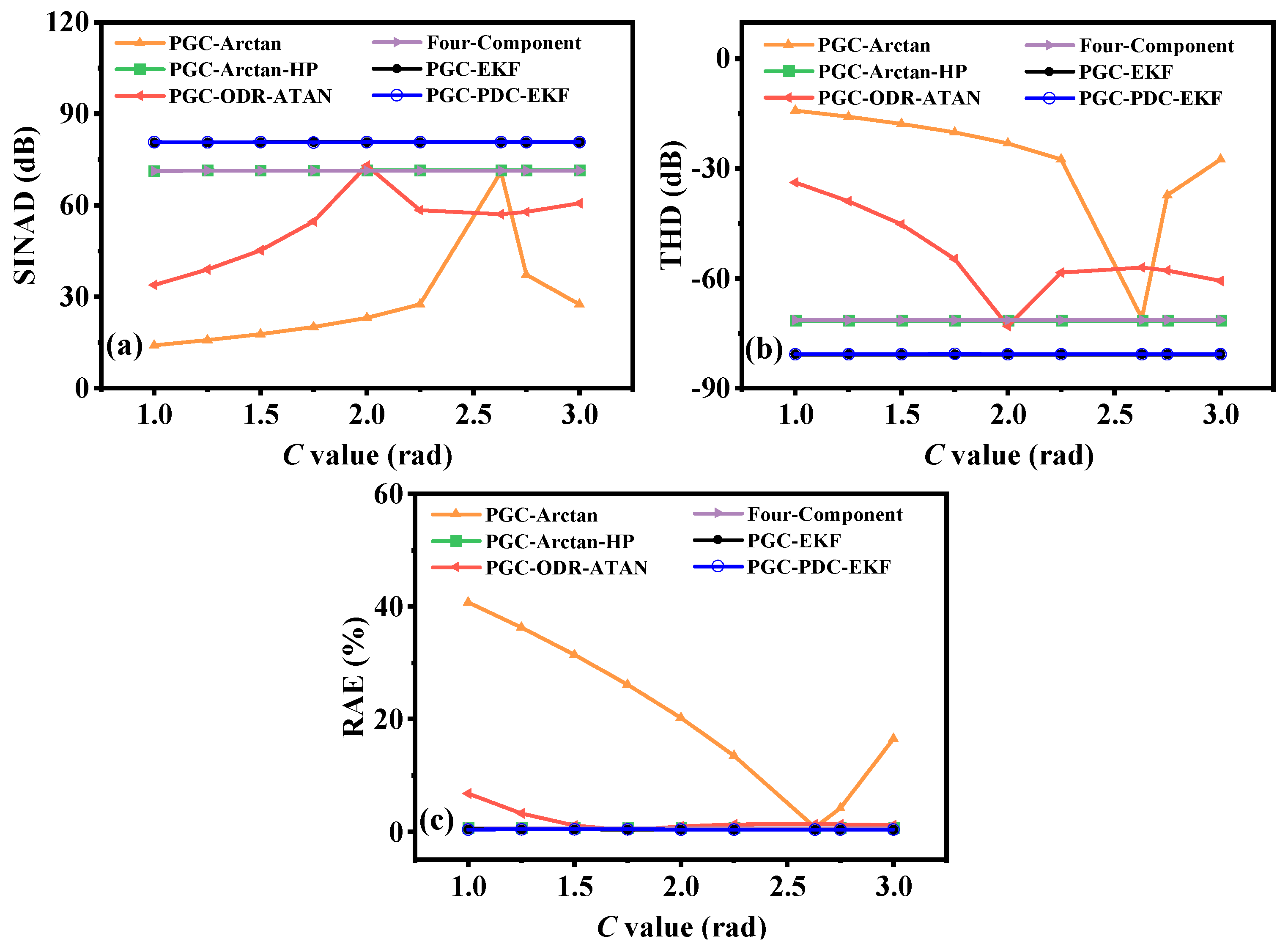
3.3. Performance Comparison of Demodulation Algorithms at Different C Value

The θ is set to 0 rad to analyze the impact of C value drifts on different demodulation algorithms. The time-domain waveforms at C values of 1.5, 2.0, 2.63 and 3.0 rad are illustrated in Figure 6. When the C value is far from the optimal value (2.63 rad), the coefficient M is not equal to 1. The demodulated signals of the PGC-Arctan scheme suffer from nonlinear distortions. By contrast, the other algorithms are unaffected by the C value drift under the same conditions.
The PGC-Arctan algorithm exhibits optimal performance only with the C value of 2.63 rad, as illustrated in Figure 7. As the C value is away from the optimal value, the SINAD of the demodulated signal decreases, the THD increases, and the RAE increases. The performance of the PGC-ODR-ATAN algorithm depends on the accuracy of the estimated value of C. Optimal performance is achieved at the C value of 2.0 rad, with a SINAD of 73.00 dB and THD of −73.01 dB. Due to the absence of carrier phase delay terms, the performance of both the PGC-EKF and PGC-PDC-EKF algorithms remains consistent.

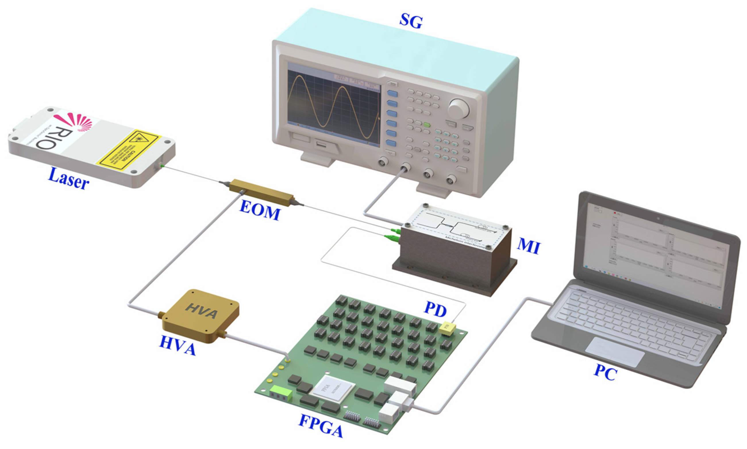
4. Experiments and Results

To evaluate the effectiveness of the proposed algorithm, an optical fiber sensing system based on the Michelson interferometer (MI) is constructed, as shown in Figure 8. A 1545.32 nm semiconductor laser with a linewidth of 1 kHz is selected as the light source. The light signal is modulated by an electro-optical modulator (EOM) with the carrier signal at the frequency of 6.25 MHz. The modulation carrier signal is output from the Field-Programmable Gate Array (FPGA) and amplified by the high-voltage amplifiers (HVA), respectively. The interferometric sensor adopts a MI structure with an arm length difference of 0.8 m and is covered with acoustic cotton to isolate external vibrations and ambient noise. In the MI, the sensing arm is wrapped around a piezoelectric transducer (PZT), which is driven by the measured phase signal output from the signal generator (SG). The two beams within the MI are reflected by a Faraday rotation mirror and interfered at the coupler. Afterward, the optical interference signals are converted into electrical signals by a photodetector (PD) and further quantized into digital signals by the analog-to-digital converter (ADC) operating at a sampling rate of 100 MS/s. Digital interference signals are demodulated in real-time by the proposed PGC demodulation algorithm on the FPGA.

4.1. Performance Analysis of PDC Module

To verify the effectiveness of the phase delay calculation and compensation module, an experiment is conducted to observe the extracted value of phase delay and the Lissajous figures of filtered signals without and with PDC. The θ is calculated 1000 times within 28.77 ms, as illustrated in Figure 9a. The mean value of the extracted θ is 0.9776 rad, and its standard deviation (STD) is 0.0065 rad. The C value is set to 2.63 rad, and the Lissajous figures of filtered signals I1(t) and I2(t) are depicted in Figure 9b. The filtered signals are non-orthogonal before the carrier phase delay is compensated. With the PDC module, the Lissajous figure of filtered signals is the unit circle.

4.2. Linearity of the Demodulated Signal

To determine the linearity of the proposed algorithm in the system, the amplitude of the measure phase signal at the output of the SG is gradually increased from 0.1 to 1.0 V. The amplitudes of demodulated signals under different amplitudes of phase signals are shown in Figure 10. It can be noted that the demodulated amplitude coincides with the linear fitting curve, and the linearity exceeds 99.99%.

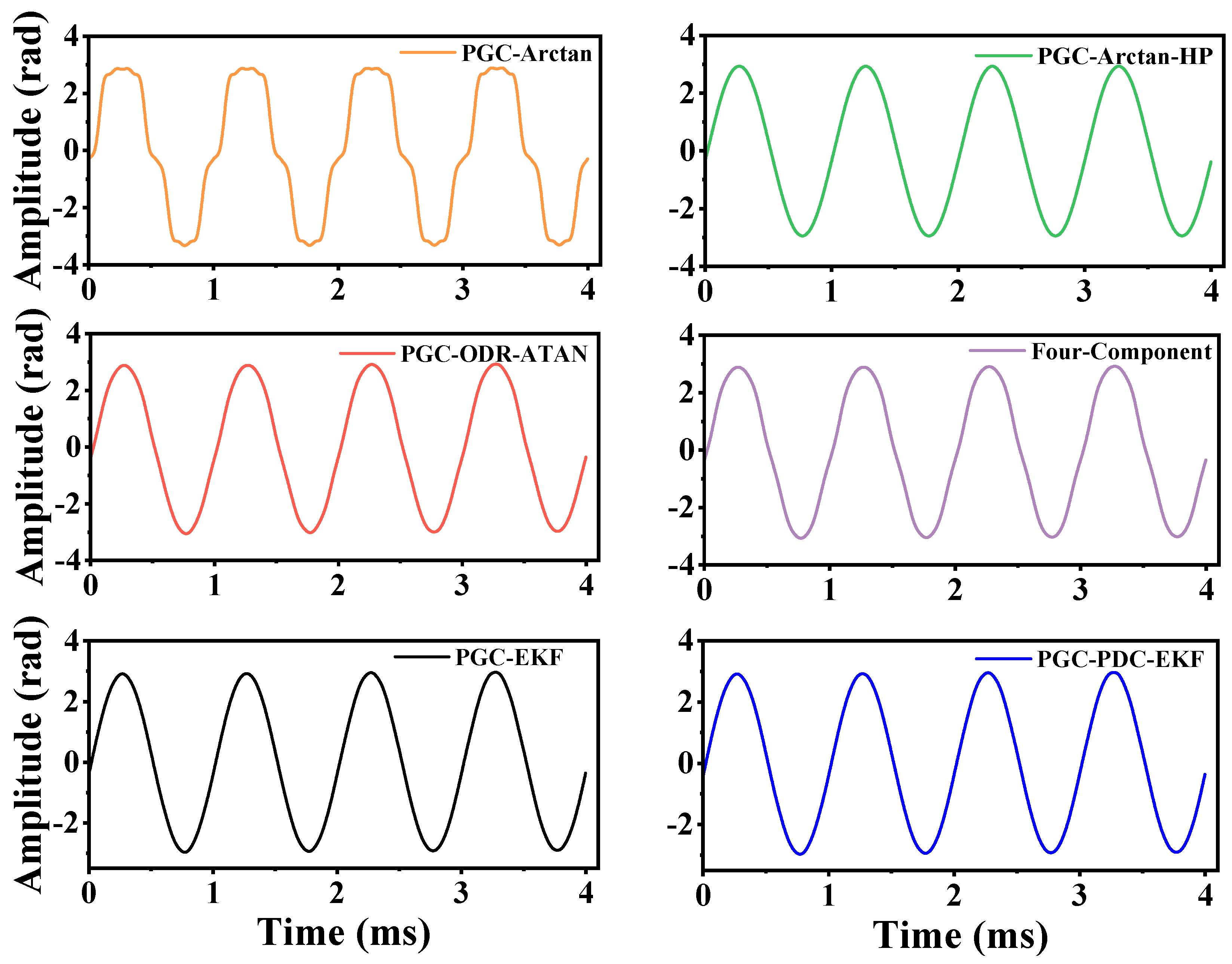
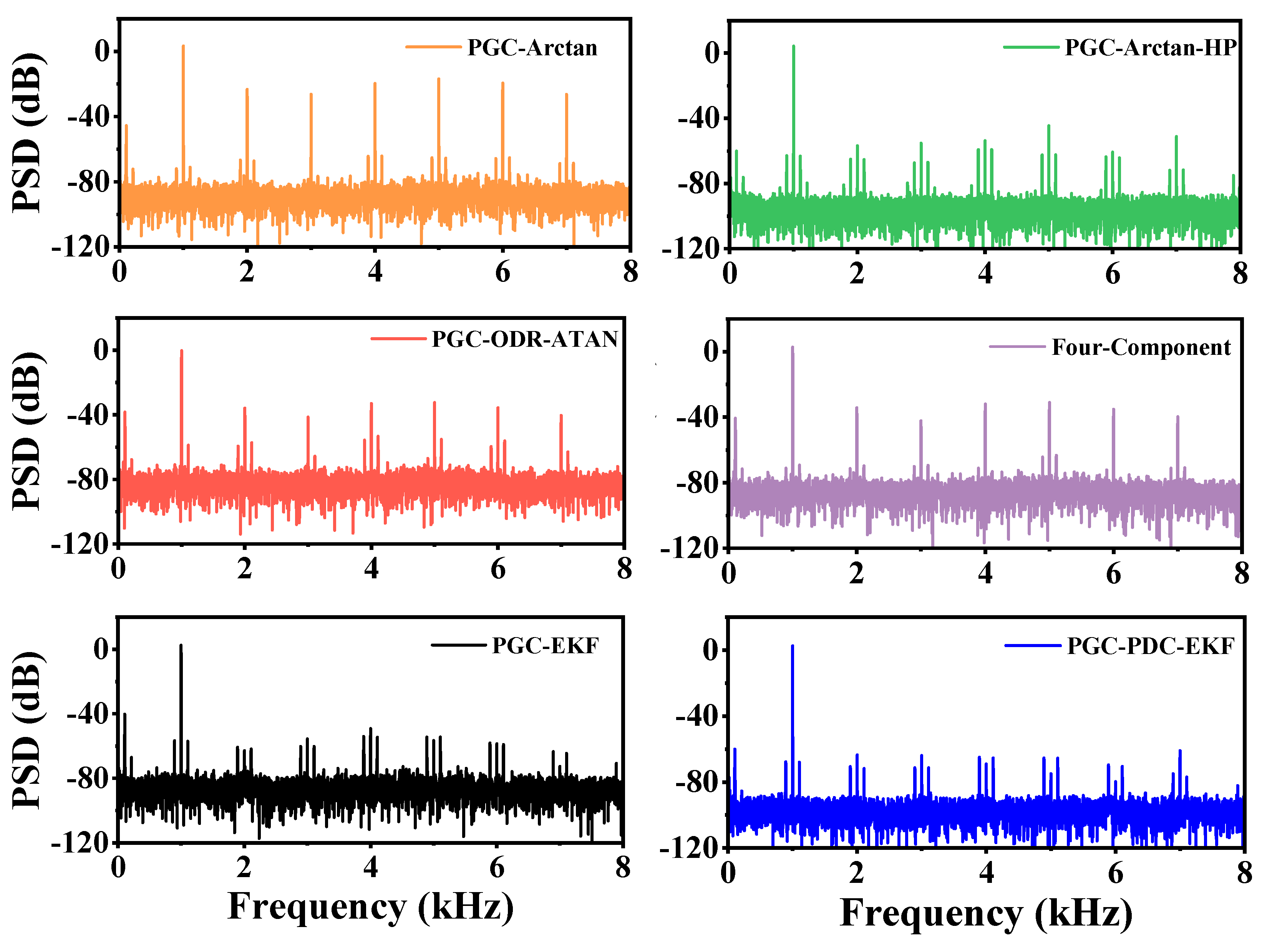
4.3. Performance Comparison of Different Algorithms

In the experiment, the C value is set to 2.63 rad by adjusting the amplitude of the modulation carrier signal. However, the C value deviates from 2.63 rad and fluctuates randomly with the drift of the half-wave voltage because of the power instability of the EOM. The carrier phase delay in the demodulated system extracted by the PDC algorithm is 0.8726 rad. The demodulated signals of different schemes are depicted in Figure 11. The waveform of the PGC-Arctan scheme is distorted due to θ and C value drift. The PGC-Arctan-HP algorithm eliminates the nonlinear distortion caused by C value drift and phase delay by harmonic mixing and phase quadrature technology. However, it fails to recover the phase signal at the phase singularities of π/4, π/2, and 3π/4 because it contains arithmetic square root operations that require sign judgment of the filter signals. The PGC-ODR-ATAN and Four-Component algorithms calculate the C value by introducing third or fourth harmonic components. Nevertheless, the calculation results of the C value are inaccurate when the phase delay exists in the system. As a result, the demodulated waveforms of both schemes suffer from nonlinear distortion. Since the carrier phase delay is not a phase singularity, the PGC-EKF algorithm is effective. In contrast, the proposed PGC-PDC-EKF scheme is independent of the θ by compensating for the θ. The proposed PGC-PDC-EKF algorithm demonstrates high stability due to its immunity to C value drift and phase delay effects.
The power spectral density (PSD) of the demodulated signals is illustrated in Figure 12. For the PGC-Arctan, PGC-ODR-ATAN, and Four-Component algorithms, nonlinear errors caused by C value drift and carrier phase delay result in the presence of high-frequency harmonic components in the phase signal. In contrast, the PGC-Arctan-HP, PGC-EKF, and PGC-PDC-EKF schemes are effective in suppressing high-frequency harmonic components. The proposed scheme has the most significant harmonic suppression and the lowest noise among them.
Moreover, to highlight the performance of PGC-PDC-EKF, the comparison of the evaluation metrics of the six algorithms for signal demodulation is shown in Table 3. The results of the metrics obtained at each algorithm are the average of 50 sets of tests. The PGC-PDC-EKF scheme achieves a SINAD as high as 54.01 dB and a THD of −62.28 dB, which ensures the accuracy of signal demodulation. By contrast, the performance of the other five schemes is degraded due to the presence of the C value drift and θ. The SINAD of the improved PGC demodulation algorithm achieves gains of 18.03 dB, 7.83 dB, 14.74 dB, 13.89 dB, and 6.05 dB, compared with PGC-Arctan, PGC-Arctan-HP, PGC-ODR-ATAN, Four-Component and PGC-EKF, respectively. The THD achieves gains of −26.04 dB, −12.51 dB, −20.81 dB, −19.75 dB, and −7.42 dB. PGC-PDC-EKF has the smallest RAE of 0.0374%, which is approaching 0, indicating that the demodulated signal is closest to the original signal. Based on the achieved results, PGC-PDC-EKF confirms its superiority over the basic PGC-Arctan algorithm and the other demodulation algorithms in all three metrics.

5. Conclusions

In summary, a high-stability PGC demodulation scheme, which integrates the PDC module and EKF algorithm, is proposed and demonstrated. The carrier phase delay is extracted and compensated with a resolution of 0.01745 rad, which guarantees the synchronization of the reference carrier with the interference signal. The high-frequency harmonic components caused by fluctuations in C value are removed by the EKF algorithm. In addition, the performance of PGC-PDC-EKF is compared with other improved algorithms, including PGC-Arctan, PGC-Arctan-HP, PGC-ODR-ATAN, Four-Component, and PGC-EKF. Experimental and evaluation results demonstrate that PGC-PDC-EKF outperforms all other demodulation algorithms in all metrics. The SINAD reaches 54.01 dB, and the THD reaches −62.28 dB. The RAE of the demodulated signal is 0.0374. The correlation coefficient between the input and output linearity of the demodulation system exceeds 99.99%. Consequently, the proposed scheme has the benefits of good stability, low harmonic distortion, and easy implementation, which exhibit great potential for application in interferometric optical fiber sensors.

Author Contributions

Conceptualization, H.Z., C.D. and Z.Z.; methodology, Z.Z.; software, C.D.; validation, C.D., Z.Z. and H.Z.; formal analysis, H.Z. and F.Z.; investigation, F.Z. and X.X.; resources, H.Z., F.Z. and X.X.; data curation, Z.Z.; writing—original draft preparation, H.Z.; writing—review and editing, H.Z. and Z.Z.; visualization, F.Z.; supervision, H.Z. and F.Z.; project administration, X.X. All authors have read and agreed to the published version of the manuscript.

Funding

This research was funded by State Grid Anhui Electric Power Co., Ltd. Technology Project (52120523000J).

Institutional Review Board Statement

Not applicable.

Informed Consent Statement

Not applicable.

Data Availability Statement

Data underlying the results presented in this paper are not publicly available at the time of publication, but may be obtained from the authors upon reasonable request.

Conflicts of Interest

The authors declare no conflicts of interest.

References

  1. Marin, Y.; Velha, P.; Oton, C.J. Distortion-corrected phase demodulation using phase-generated carrier with multitone mixing. Opt. Express 2020, 28, 36849–36861. [Google Scholar] [CrossRef] [PubMed]
  2. Yu, Z.; Zhang, Q.; Zhang, M.; Dai, H.; Zhang, J.; Liu, L.; Zhang, L.; Jin, X.; Wang, G.; Qi, G. Distributed optical fiber vibration sensing using phase-generated carrier demodulation algorithm. Appl. Phys. 2018, 124, 84. [Google Scholar] [CrossRef]
  3. He, J.; Wang, L.; Li, F.; Liu, Y. An ameliorated phase generated carrier demodulation algorithm with low harmonic distortion and high stability. J. Light. Technol. 2010, 28, 3258–3265. [Google Scholar]
  4. Zhang, A.; Li, D. Interferometric sensor with a PGC-AD-DSM demodulation algorithm insensitive to phase modulation depth and light intensity disturbance. Appl. Opt. 2018, 57, 7950–7955. [Google Scholar] [CrossRef]
  5. Azmi, A.I.; Leung, I.; Chen, X.; Zhou, S.; Zhu, Q.; Gao, K.; Childs, P.; Peng, G. Fiber laser-based hydrophone systems. Photon. Sens. 2011, 1, 210–221. [Google Scholar] [CrossRef]
  6. Liu, Y.; Wang, L.; Tian, C.; Zhang, M.; Liao, Y. Analysis and optimization of the PGC method in all digital demodulation systems. J. Light. Technol. 2018, 26, 3225–3233. [Google Scholar] [CrossRef]
  7. Gui, L.; Wu, X.; Yu, B.; Guang, D.; Shi, J.; Zuo, C. High-stability PGC demodulation algorithm based on a reference fiber-optic interferometer with insensitivity to phase modulation depth. J. Light. Technol. 2021, 39, 6968–6975. [Google Scholar] [CrossRef]
  8. Li, Y.; Gao, H.; Zhao, L.; Fu, Z.; Zhang, J.; Li, Z.; Qiao, X. Improved PGC demodulation algorithm to eliminate modulation depth and intensity disturbance. Appl. Opt. 2022, 61, 5722–5727. [Google Scholar] [CrossRef]
  9. Volkov, A.V.; Plotnikov, M.Y.; Mekhrengin, M.V.; Miroshnichenko, G.P.; Aleynik, A.S. Phase modulation depth evaluation and correction technique for the PGC demodulation scheme in fiber-optic interferometric sensors. IEEE Sens. J. 2017, 17, 4143–4150. [Google Scholar] [CrossRef]
  10. Gong, Y.; Shi, J.; Guang, D.; Zhou, M.; Mu, S.; Wu, X. Improved algorithm for phase generation carrier to eliminate the influence of modulation depth with multi-harmonics frequency mixing. J. Light. Technol. 2023, 41, 1357–1363. [Google Scholar] [CrossRef]
  11. Zhang, S.; Yan, L.; Chen, B.; Xu, Z.; Xie, J. Real-time phase delay compensation of PGC demodulation in sinusoidal phase-modulation interferometer for nanometer displacement measurement. Opt. Express 2017, 25, 472–485. [Google Scholar] [CrossRef]
  12. Nikitenko, A.N.; Plotnikov, M.Y.; Volkov, A.V.; Mekhrengin, M.V.; Kireenkov, A.Y. PGC-Atan demodulation scheme with the carrier phase delay compensation for fiber-optic interferometric sensors. IEEE Sens. J. 2018, 18, 1985–1992. [Google Scholar] [CrossRef]
  13. Yan, L.; Zhang, Y.; Xie, J.; Lou, Y.; Chen, B.; Zhang, S. Nonlinear error compensation of PGC demodulation with the calculation of carrier phase delay and phase modulation depth. J. Light. Technol. 2021, 39, 2327–2335. [Google Scholar] [CrossRef]
  14. Xie, J.; Yan, L.; Chen, B.; Lou, B. Extraction of carrier phase delay for nonlinear errors compensation of PGC demodulation in an SPM interferometer. J. Light. Technol. 2019, 37, 3422–3430. [Google Scholar] [CrossRef]
  15. Hou, C.; Liu, G.; Guo, S.; Tian, S.; Yuan, Y. Large dynamic range and high sensitivity PGC demodulation technique for tri-component fiber optic seismometer. IEEE Access 2020, 8, 15085–15092. [Google Scholar] [CrossRef]
  16. Ni, C.; Zhang, M.; Zhu, Y.; Hu, C.; Ding, S.; Jia, Z. Sinusoidal phase modulating interferometer with ellipse fitting and a correction method. Appl. Opt. 2017, 56, 3895–3899. [Google Scholar] [CrossRef] [PubMed]
  17. Zhang, G.; Xu, L.; Ge, Q.; Wu, X.; Yu, B. High precision and stabilization PGC demodulation scheme for fiber optic interferometric sensors. J. Light. Technol. 2023, 41, 6615–6620. [Google Scholar] [CrossRef]
  18. Shapiro, R. Smoothing, filtering, and boundary effects. Rev. Geophys. 1970, 8, 359–387. [Google Scholar] [CrossRef]
  19. Zhe, Y.; Lian, B.; Tong, K.; Chen, S. Novel strong tracking square-root cubature kalman filter for GNSS/INS integrated navigation system. IET Radar Sonar Navig. 2019, 13, 976–982. [Google Scholar]
  20. Yan, L.; Chen, Z.; Chen, B.; Xie, J.; Zhang, S.; Lou, Y.; Zhang, E. Precision PGC demodulation for homodyne interferometer modulated with a combined sinusoidal and triangular signal. Opt. Express 2018, 26, 4818–4831. [Google Scholar] [CrossRef]
  21. Zhu, M.; Wang, X.; Chang, J.; Zhou, H. Improved PGC demodulation algorithm for fiber optic interferometric sensors. Opt. Express 2024, 32, 2162–2178. [Google Scholar] [CrossRef] [PubMed]
  22. Zhou, W.; Yu, B.; Zhang, J.; Shi, J.; Guang, D.; Zuo, C.; Mu, S.; Liu, Y.; Lin, Z.; Wu, X. Ameliorated PGC demodulation technique based on the ODR algorithm with insensitivity to phase modulation depth. Opt. Express 2023, 31, 7175–7186. [Google Scholar] [CrossRef] [PubMed]
  23. Chang, N.; Huang, X.; Wang, H. Phase generated carrier demodulation approach in fiber-optic hydrophone based on extended Kalman filter parameter estimation. Chin. J. Lasers 2022, 49, 103–114. [Google Scholar]
Figure 1. The basic PGC-Arctan demodulation scheme. MUL: multiplier. LPF: low-pass filter. DIV: division. Arctan: arctangent.
Photonics 12 00044 g001
Figure 2. Principle of PGC-PDC-EKF demodulation scheme. DDS: direct digital synthesizer. δ: compensation phase. ABS: Absolute. δx: θ_extracted value. I1, I2: filtered signals with phase delay compensation. EKF: extended Kalman filter. E, F, G, H: ellipse parameters. hx, kx, ax, bx: ellipse correction parameters. I1′, I2′: orthogonal signals with the EKF processing.
Photonics 12 00044 g002
Figure 3. The dependence of the minimum value of H(δ) on the C value.
Photonics 12 00044 g003
Figure 4. Demodulated signal waveforms for different algorithms under phase delays.
Photonics 12 00044 g004
Figure 5. Performance analysis of demodulation algorithms under phase delay from 0 to π rad in simulation. (a) SINAD of different algorithms; (b) THD of different algorithms; (c) RAE of different algorithms.
Photonics 12 00044 g005
Figure 6. Demodulated signal waveforms for different algorithms under C value drift.
Photonics 12 00044 g006
Figure 7. Performance analysis of demodulation algorithm at different C value in simulation. (a) SINAD of different algorithms; (b) THD of different algorithms; (c) RAE of different algorithms.
Photonics 12 00044 g007
Figure 8. Experimental setup of the PGC demodulation system.
Photonics 12 00044 g008
Figure 9. Automatic phase delay calculation and compensation. (a) Phase delay extracted value in 30 ms; (b) Lissajous figures of I1 (t) and I2 (t) without and with PDC.
Photonics 12 00044 g009
Figure 10. The linearity of the PGC-PDC-EKF demodulation algorithm.
Photonics 12 00044 g010
Figure 11. Time-domain waveforms of different PGC algorithms in the experiment.
Photonics 12 00044 g011
Figure 12. PSD of different PGC algorithms in the experiment.
Photonics 12 00044 g012
Table 1. Comparison of phase delay calculation results at different step sizes.
Step Size l (Rad)Set θ
(Rad)
Calculated δx
(Rad)
Error
(%)
Resolution
(Rad)
Time
(s)
π/451.553381.535891.12590.069810.086
π/901.553381.570801.12140.034900.088
π/1801.553381.553340.00250.017450.093
π/3601.553381.553340.00250.008730.144
Table 2. Phase singularities of different algorithms in 0 to π.
AlgorithmPhase Singularities
PGC-Arctanπ/4π/23π/4
PGC-Arctan-HPπ/4π/23π/4
PGC-ODR-ATANπ/6π/4π/23π/45π/6
Four-Componentπ/6π/4π/23π/45π/6
PGC-EKFπ/4π/23π/4
PGC-PDC-EKF
Table 3. Evaluation index comparison of different demodulation algorithms.
AlgorithmRAE (%)SINAD (dB)THD (dB)
PGC-Arctan13.474235.98−36.24
PGC-Arctan-HP1.614546.18−49.77
PGC-ODR-ATAN4.353039.27−41.47
Four-Component3.910640.12−42.53
PGC-EKF0.987047.96−54.86
PGC-PDC-EKF0.037454.01−62.28
Disclaimer/Publisher’s Note: The statements, opinions and data contained in all publications are solely those of the individual author(s) and contributor(s) and not of MDPI and/or the editor(s). MDPI and/or the editor(s) disclaim responsibility for any injury to people or property resulting from any ideas, methods, instructions or products referred to in the content.

