1. Introduction
Recently, high-power fiber lasers have been developed rapidly, along with advancements in fiber materials and laser technology [
1,
2]. Among these, high-power Tm
3+-doped fiber lasers have attracted more and more attention, thanks to the unique propagation properties in the atmosphere and the strong absorption characteristics in water molecules and transparent material [
3]. In particular, with the development of light source requirements for laser medical treatment, material processing, remote sensing, nonlinear optics, and other applications, the demand for high-power, narrow-linewidth Tm
3+-doped fiber lasers in the 2.0 µm wavelength range has gradually enhanced [
4,
5]. Compared with fiber lasers operating in the 1.0 µm wavelength range, 2.0 µm fiber lasers face challenges such as lower quantum efficiency in direct diode pumping, increased thermal load, and susceptibility to transverse mode instability (TMI) [
6,
7]. Moreover, scaling the power of narrow-linewidth Tm
3+-doped fiber lasers is confronted with the challenge of the stimulated Brillouin scattering (SBS) effect. Therefore, achieving high-power and narrow-linewidth laser output in Tm
3⁺-doped fiber lasers requires comprehensive system design and optimization.
The master oscillator power amplifier (MOPA) frame is a widely adopted technique for laser amplification, and some researchers have made progress in Tm
3+-doped fiber amplifiers (TDFAs). For single-frequency TDFA, Guan et al. [
8] achieved a 316 W, single-frequency, linearly polarized, near-diffraction-limited all-fiber laser output at 1950 nm. This is the highest output power in single-frequency all-fiber TDFAs, but further power increase is challenging. Regarding narrow-linewidth TDFAs, T. Ehrenreich et al. [
9] reported the first kilowatt-level TDFA at 2045 nm with a slope efficiency of 53.2% using a two-stage MOPA configuration. Regrettably, the specific linewidth and beam quality results are not provided. W. Yao et al. [
10] demonstrated a beam-combined Tm
3+-doped fiber laser system with an output power of 790 W and a slope efficiency of 52.2%. However, the incoherent beam combination technique increases the system’s complexity and reduces the beam quality (M
2 = 2.7). Subsequently, J. S. Shin et al. [
11] employed a single-mode Tm
3+-doped fiber oscillator for amplification, achieving a 200 W output power at 2050 nm with a slope efficiency of 53.0%. However, thermal management challenges limit further power increases, such as temperatures up to 92 °C at the pump injection point and the emergence of multiple transverse modes. In the same year, B. M. Anderson et al. [
12] used specially configured pedestal fibers and achieved 1.1 kW output with a 51% slope efficiency and a linewidth of 5 GHz at 1950 nm. Recently, an all-fiber integrated wavelength-tunable TDFA at 2.0 μm with output powers exceeding 1 kW and slope efficiencies above 51% is first reported. Nevertheless, the spectral linewidth is broadened to 0.5 nm (~39 GHz) due to the nonlinear effects [
13].
Despite significant advancements in developing high-power Tm
3+-doped fiber lasers, with output powers exceeding the kilowatt scale, several critical challenges remain. One major issue is achieving the balance between power scaling and linewidth narrowing, which is crucial for applications requiring high spectral monochromaticity [
14,
15]. Another challenge is effectively managing heat to prevent fiber thermal damage and mitigate thermally induced mode instability, especially at kilowatt-level powers. Researchers have explored various strategies, including advanced fiber designs, innovative pumping techniques, and specialized heat dissipation systems [
1,
16,
17,
18]. However, realizing a fully integrated solution that combines high power, narrow linewidth, and excellent beam quality in a robust, all-fiber configuration remains a significant challenge.
In this article, a kilowatt-level, high-efficiency, narrow-linewidth, high-brightness all-fiber integrated Tm3+-doped fiber laser is demonstrated. Based on a two-stage main amplifier, it achieves over 1 kW laser output at 1950 nm with a linewidth of 3.8 GHz and a slope efficiency greater than 58%. The beam quality factor M2 is estimated to be ~1.19. Further power scaling is predictable with elevated pump power, considering the absence of parasitic oscillation or self-pulsing effects even at the maximum laser power level.
2. Experiment Setup
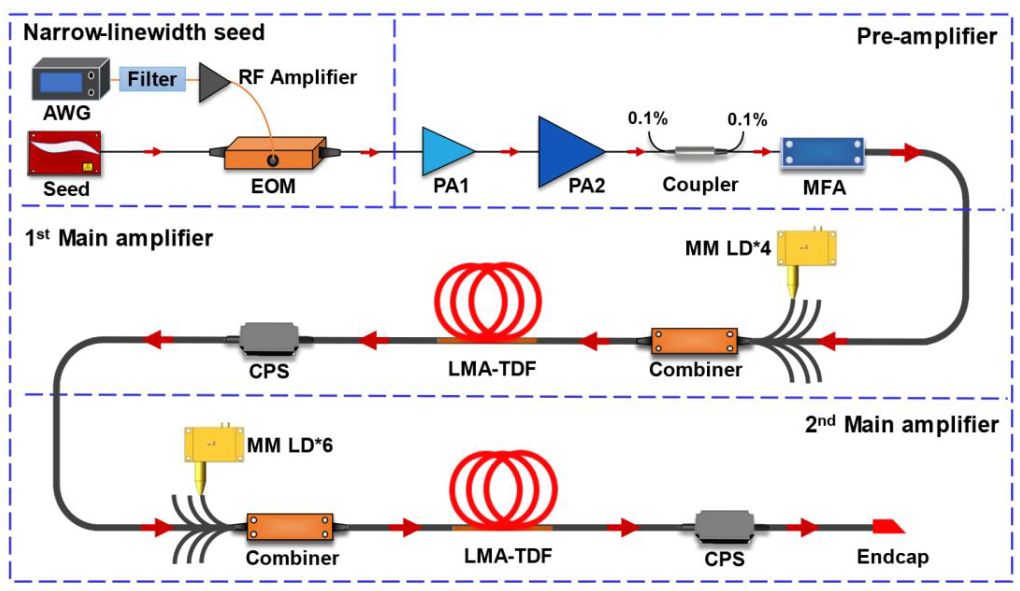
Figure 1 shows the schematic of a high-power, narrow-linewidth Tm
3+-doped fiber laser. The laser system comprises a narrow-linewidth seed oscillator, two pre-amplifiers, and two main power amplifiers. The seed light originates from a self-made distributed Bragg reflector single-frequency fiber laser (SFFL) operating at 1.95 µm. Given that the SBS threshold is closely related to the power spectral density of the signal, broadening the spectrum reduces the power density per unit frequency, thereby decreasing the likelihood of Brillouin scattering and increasing the SBS threshold [
19]. Then, the seed light is injected into an electro-optic phase modulator (EOM), which is applied to broaden the linewidth of the seed signal and increase the SBS threshold. Thanks to its low complexity and high flexibility, a binarized multi-frequency signal is chosen as the phase-modulated signal, which can attain a flat-top-shaped spectrum. The designed binarized multi-frequency signal, generated by an arbitrary waveform generator (AWG), is filtered to eliminate digital-to-analog conversion noise. After that, this electrical signal is amplified by a radio frequency (RF) amplifier and loaded to the modulation port of EOM.
The pre-amplifier consists of a two-stage configuration, each utilizing a 3 m double-clad Tm3+-doped fiber (TDF) with a core/cladding diameter of 10/130 μm (numerical aperture (NA) = 0.15/0.46) and a cladding absorption coefficient of 3 dB/m at ~793 nm. Pre-amplifier 1 (PA1) is pumped by a 5 W fiber-coupled multimode laser diode (MM LD) through a (2 + 1) × 1 signal pump combiner, while a 30 W MM LD is used for pre-amplifier 2 (PA2). To ensure the unidirectional propagation of the signal light, a 2 W isolator with 30 dB isolation is equipped at the end of PA1, and another 20 W isolator with 30 dB isolation is applied to PA2. The signal power is amplified from 15 mW to 10.6 W across both pre-amplifier stages, while two 0.1% taps are provided for monitoring the forward signal light and backward reflected light.
Following pre-amplifiers, the signal light is further amplified in a two-stage main amplifier setup. The main amplifiers have adopted a large-mode-area TDF (LMA-TDF) with a core/cladding diameter of 25/400 µm (NA = 0.11/0.46) and a cladding absorption coefficient of ~2 dB/m at 793 nm as the gain medium, and the pump lights have employed 793 nm MM LDs with 240 W of individual pump power and a NA of 0.22. Each LD operates at a voltage of 65 V with a current limit of 10 A, and the system is powered by a 250 V/120 A AC-DC power supply. Considering the low quantum efficiency of TDF in the 3H6→3H4 energy conversion process, the high NA of the pump light, and the high absorption coefficient of the gain fiber, these factors will lead to significant heat together within a short section of the gain fiber at the pump injection point. If not effectively designed, this concentrated heat could potentially lead to burnout of this fiber amplifier system. To address this inherent challenge in high-power Tm3+-doped fiber amplifiers, two stages of the Tm3+-doped fiber are meticulously placed on aluminum plates. The primary advantage of this two-stage approach lies in its ability to distribute the thermal load more evenly across the amplifications, thereby mitigating the risk of localized overheating that could lead to fiber damage. The high thermal conductivity of aluminum, combined with the efficient heat transfer properties of the water-cooling system, ensures that the heat generated within the fiber cores is rapidly conducted away from the active regions. This thermal management strategy not only prevents excessive temperature rise but also maintains a stable operating environment for the fiber, which is crucial for sustaining high power output and ensuring long-term reliability.
The signal light is guided through a mode-field adapter (MFA) into the 1st main amplifier. The LMA-TDFs are optimized to 7 m in both amplifiers to ensure efficient amplification and minimize nonlinear effects. The main amplifiers are co-pumped by ten 240 W MM LDs, through two (6 + 1) × 1 combiners. Considering that the maximum allowable output power for PA2 is only 10.6 W, the pumping power of the two-stage main amplifier needs scientific distribution to prevent pump over-saturation in the 1st main amplifier and then reduce the pump efficiency due to non-radiative transitions. Therefore, the 1st main amplifier employs four MM LDs, and the 2nd main amplifier uses six MM LDs, which is conducive to the controlled extraction of optical gain and improves the optical conversion efficiency. The unused pump fibers in the combiner are cut at an angle of 8° to avoid unwanted reflections. Two cladding power strippers (CPSs) are employed to remove the residual pump laser and cladding signal light in each main amplifier stage. To achieve efficient heat dissipation and enhance system stability, the LMA-TDFs and MM LDs are placed on water-cooled aluminum plates maintained at 17 °C, which is the minimum cooling temperature of the chiller. The LMA-TDFs are coiled with a diameter of 12 cm in tightly fitting channels to increase the loss of higher-order modes and prevent the occurrence of the TMI effect. An angle-cleaved coreless fiber endcap with an 8° angle and a diameter of 400 µm is fused to the output end to prevent unwanted optical feedback and to protect the end facet.
3. Experimental Results and Discussion
The optical spectra of the seed laser with and without phase modulation are measured using an optical spectrum analyzer (AQ6376E, Yokogawa, Musashino, Japan) with a resolution of 0.1 nm and a scanning range from 1850 to 2050 nm, as shown in
Figure 2a. Moreover, detailed spectra with a span of 4 nm are also measured and shown in the inset of
Figure 2a, which shows that the center wavelength of the signal laser is located at ~1950 nm. After phase modulation, a slight broadening of the optical spectrum is observed. However, it is difficult to accurately measure the laser linewidth due to the resolution limitation (0.1 nm) of the optical spectrum analyzer. Therefore, another method is adopted to measure the laser linewidth later. The seed spectra exhibit remarkable monochromaticity, with an optical signal-to-noise ratio (OSNR) exceeding 61 dB, and there are no obvious ASE and other parasitic laser emissions. This optical characteristic is essential for achieving efficient amplification at the central wavelength of ~1950 nm in subsequent stages. Initially, the output power of the SFFL is measured at 34 mW, and the laser power decreases to 15.2 mW after passing through the EOM, primarily attributed to the insertion loss of ~3.5 dB introduced by the EOM.
In order to measure the linewidth of the seed laser without phase modulation, the delayed self-heterodyne method with an 80 MHz frequency shift is employed [
20]. The inset of
Figure 2b presents the measurement results. The spectral data are fitted to a Lorentzian profile, revealing a 20 dB spectral width of 252 kHz, corresponding to a 3 dB linewidth of approximately 12.6 kHz [
21]. Afterward, a phase modulation technique is applied to broaden the linewidth of the seed laser. Given that the broadened linewidth exceeds the measurement range of the delayed self-heterodyne method, a delayed self-homodyne technique [
22,
23] is utilized instead. This technique involved a Mach–Zehnder interferometer (MZI) with a 3 m delay fiber. As depicted in
Figure 2b, the self-homodyne signal is fitted to a Gaussian profile, and the 3 dB spectral half-width is measured to be 3.8 GHz, indicating the linewidth of the laser is 3.8 GHz [
24,
25,
26].
The seed laser is subsequently injected into the pre-amplifiers to further enhance its power.
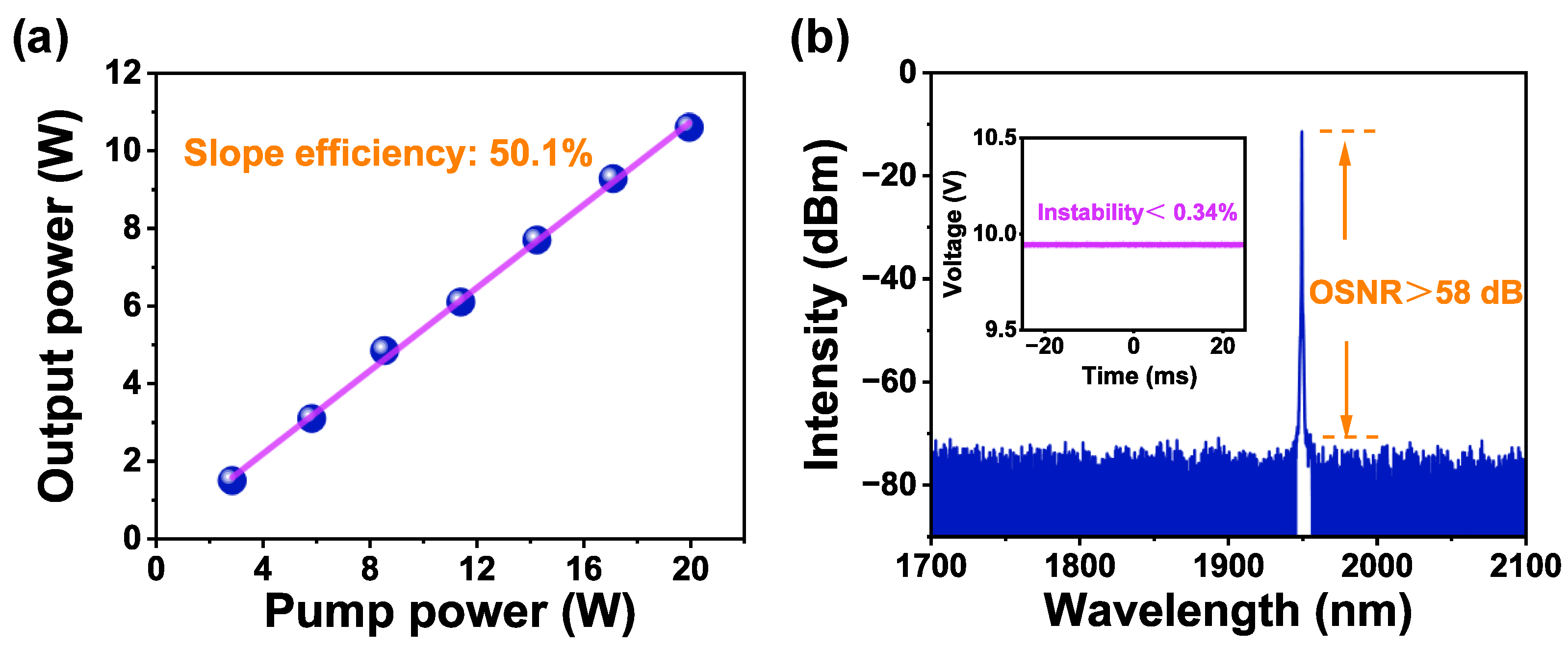
Figure 3a illustrates the output power versus pump power in PA2, with a slope efficiency of 50.1%. At 20 W pump power, the signal laser output reaches 10.6 W.
Figure 3b displays the output optical spectrum of PA2, showing no significant signs of ASE or parasitic lasing, attributed to optimized fiber length and radius bending of the pre-amplifiers. The OSNR exceeds 58 dB, which is crucial for raising the threshold of nonlinear effects. The inset in
Figure 3b confirms favorable time-domain stability at 10.6 W output, preventing premature stimulated Raman scattering (SRS) effect [
27].
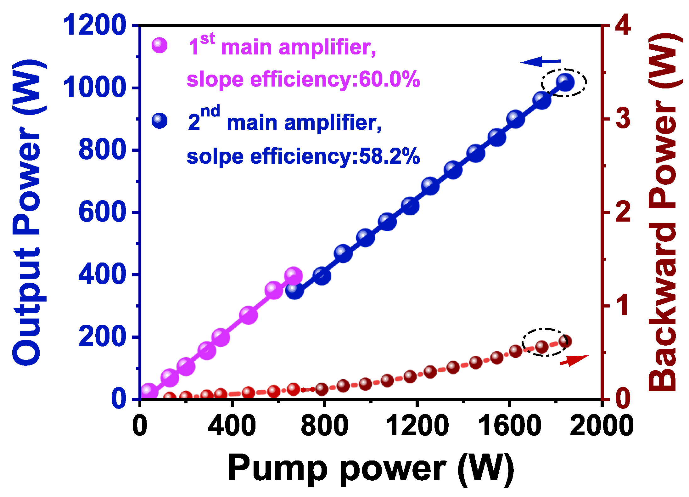
Figure 4 illustrates the curve of output power and backward light power versus pump power for the 1st main amplifier and the 2nd main amplifier, with the output power of each stage directly measured by a power meter. For the 1st main amplifier, as shown in the pink scatterplot in
Figure 4, the output power reaches 396 W linearly while the pump power increases to 665 W, with a corresponding slope efficiency of 60.0%, which can be attributed to the optimization of the length of the LMA-TDF. The power of the 1st main amplifier is not further increased due to the input signal power handling limitation of the (6 + 1) × 1 signal–pump combiner in the 2nd main amplifier.
For the 2nd main amplifier, as shown in the blue scatterplot in
Figure 4, the output power increases linearly throughout the process. When the pump power increases to 1820 W, the output power climbs to 1018 W with a corresponding slope efficiency of 58.2%. As for electric power consumption, this system consumes approximately 3.5 kW in total. The slight decrease in the slope efficiency compared to the 1st main amplifier is attributed to the high signal and pump power levels injected into the LMA-TDF in the 2nd main amplifier, which causes core heating and consequently reduces efficiency. The elevated temperature of the gain medium affects its physical properties, increasing the probability of non-radiative transitions. This results in the pump energy being dissipated as heat rather than being converted into signal light, thereby reducing the quantum efficiency and, consequently, the overall slope efficiency of the amplification process [
28,
29,
30]. Fortunately, this slope efficiency is remarkably high for high-power Tm
3+-doped fiber amplifiers.
It is worth noting that there is a discontinuity at 665 W pump power in
Figure 4, resulting from partial absorption of the signal light by the LMA-TDF when it passes through the 2nd main amplifier. Additionally, the backward propagating light is monitored through the 0.1% port of the coupler in the pre-amplifier, showing linear growth in
Figure 4. At the maximum output power, the backscattered light reaches 668 mW without any exponential growth. The linear increase in the backward power indicates that SBS and SRS have not occurred at the kilowatt output power level [
31]. Furthermore, the signal power is only limited by the available pump power and can be further enhanced with more powerful 793 nm laser diodes.
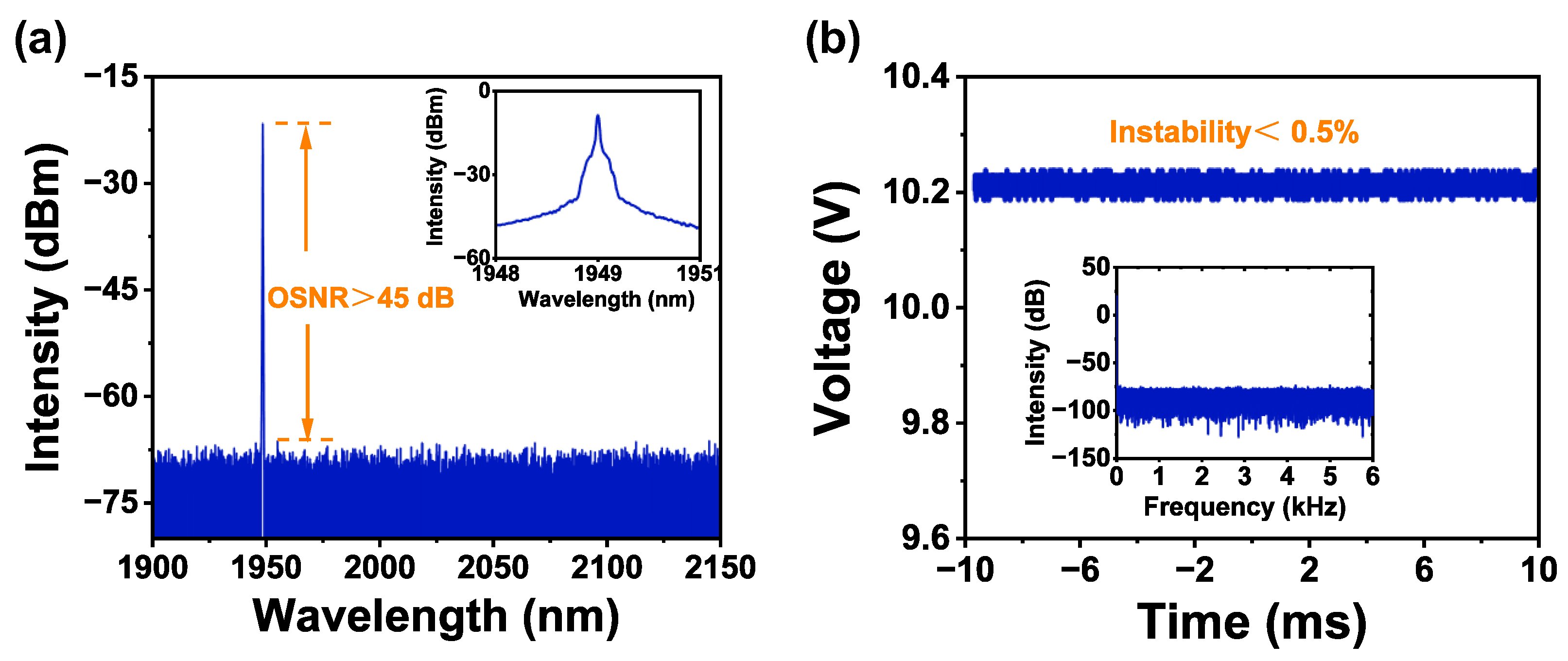
At the maximum output power of 1018 W, the laser spectrum is measured using an optical spectrum analyzer with a scanning resolution of 0.1 nm. The power injected into the spectrometer is controlled to 1.0 mW by combining a wedge splitter with a focusing mirror. As shown in
Figure 5a, the output spectrum of the kilowatt-level Tm
3+-doped fiber laser exhibits an OSNR greater than 45 dB, with no obvious ASE or SRS content within the 1900–2150 nm range. The inset, displaying a narrow scanning range of 3 nm, reveals a sharp single-peak distribution, confirming that the signal maintains excellent monochromaticity even at a kilowatt-level output power at 1.95 μm. In
Figure 5b and its inset, time-domain signals and their corresponding Fourier spectra are recorded to assess whether the TMI effect and self-phase modulation (SPM) are present.
Figure 5b shows that the time-domain instability is only 0.5% at an output power of 1018 W over 20 ms, with no evidence of self-pulsing or periodic oscillations due to SPM. Additionally, the inset in
Figure 5b shows no typical discrete frequency peak in the Fourier spectra within 0–6 kHz, indicating that nonlinear effects have not occurred at the kilowatt output power level [
32,
33].
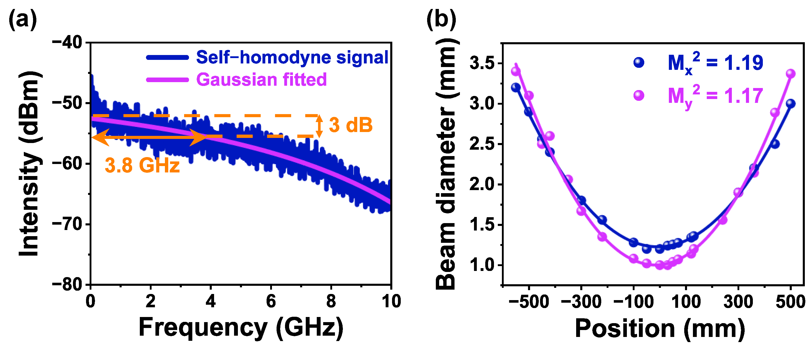
Figure 6a illustrates the self-homodyne signal of the amplified Tm
3+-doped fiber laser at its maximum output power, captured by a real-time spectrum analyzer (Tektronix, Beaverton, OR, USA, RSA-5115B) with a resolution bandwidth of 50 MHz. The Gaussian fit of the spectral linewidth curve shows a 3 dB half-width of 3.8 GHz, confirming that the linewidth of the amplified Tm
3+-doped fiber laser is 3.8 GHz at maximum output power. Notably, compared to the seed laser, the amplified laser output shows no broadening of the spectral linewidth or any other forms of deformation, which can be attributed to the absence of significant ASE and SPM in the signal spectrum [
32].
Furthermore, the transverse mode properties of the output laser are assessed using a beam-scanning slit analyzer. As illustrated in
Figure 6b, the spot diameter is measured at different positions along the beam propagation path. After the hyperbolic fitting, the beam quality factors, M
x2 and M
y2, are determined to be 1.19 and 1.17 at the maximum output power, respectively. Despite the relatively large core diameter of the fiber utilized in the main amplifiers, optimizing the fiber coiling diameter effectively suppressed the propagation of higher-order modes within the bent sections of the fiber. At the maximum output power, the measured M
2 remains close to the diffraction limit, indicating that the TMI effect and thermal lensing effect have not occurred [
34]. Thanks to the two-stage main amplifier design and optimized pump power configuration, the 2.0 µm narrow-linewidth Tm
3+-doped fiber laser steadily achieves kilowatt-level output power using only aluminum water-cooled plates for heat dissipation. This approach significantly enhances the laser system’s practicality for various applications.
4. Conclusions
In conclusion, we have achieved a kilowatt-level, high-efficiency, narrow-linewidth, high-brightness, all-fiber Tm3+-doped continuous-wave laser operating at 1.95 µm. A phase-modulated SFFL is used as the narrow-linewidth seed laser, which has improved the SBS threshold and achieved optical spectrum control. By strategically dispersing heat deposition across two main amplifiers and optimizing the gain fiber length, the controlled extraction of optical gain is realized, and the optical conversion efficiency is improved. Using 793 nm MM LD pumping and a 10 W input signal, a 1.95 µm fiber laser is demonstrated with 1018 W output, 3.8 GHz linewidth, and 60.0% slope efficiency. The beam quality factors Mx2 and My2 are measured to be 1.19 and 1.17, respectively, with an OSNR exceeding 45 dB. To our knowledge, this represents the narrowest linewidth and the highest slope efficiency for a kilowatt-level Tm3+-doped fiber laser. These results underscore the significant potential of this high-power, narrow-linewidth, high-brightness 2.0 μm fiber amplifier in advancing applications such as remote sensing and lidar, particularly in atmospheric detection and characterization.
