1. Introduction
A diffraction grating (DG) is an optical element that produces a periodic change in an incident electromagnetic wave’s amplitude and/or phase. The invention and use of diffraction gratings have a long history, beginning in the late 18th century [
1,
2]. Moreover, reflection diffraction gratings, which are close to the modern ones, were already created in the early 19th century [
2,
3].
The highest energy efficiency concentrated in one diffraction order is provided by gratings with a continuous echelette phase profile (blazed gratings), but they are the most complex from a technology perspective. Binary gratings are much easier to make; however, they create many diffraction orders, and therefore their energy efficiency is limited. However, if we take into account and apply the action of at least three main diffraction orders, then in total they provide more than 80% of the diffraction efficiency for the phase binary element (40.5% in ±1 orders) [
4] and 45% of the amplitude binary element (25% in the zero order and 10% in ±1 orders) [
5]. The combination of several diffraction orders allows for the use of laser processing with several beams simultaneously [
6]. It is noteworthy that the dispersion characteristics of the amplitude elements ensure the independence of the wavelength for short pulses. In addition, fork-like gratings are promising in problems of mode and/or polarization state detection [
7] when diffraction efficiency is not a crucial factor.
Two of the main applications of diffraction gratings are the separation and replication of an incident beam. Gratings that provide uniform separation of an incident beam into a given number of diffraction orders are called Dammann gratings [
8,
9].
In this case, not only precise calculation but also precision in the fabrication of such gratings is required [
10,
11]. Another well-known application of gratings is their use as dispersive elements in spectral devices [
12,
13].
Recently, periodic structures of various types (amplitude, phase, combined) are not only manufactured using specially developed technologies [
14,
15], but are also formed by the interaction of radiation with matter [
16,
17,
18,
19,
20], especially when laser structuring the surfaces of photosensitive materials [
17,
18,
19].
A special type of diffraction grating is a resonant diffraction grating. In their structures, the contrast in the grooves is achieved by the spatial modulation of the resonant properties of the medium. Such a resonance can be an exciton in a quantum well [
21,
22,
23] or an exciton in a three-dimensional semiconductor [
24].
The simplest method of modulation is the introduction of an additional inhomogeneous broadening into the resonance using local defect formation. For epitaxial heterostructures, this can be achieved thanks to a preliminary treatment of the substrate [
21]. For the post-growth modulation, irradiation with a focused beam of high-energy ions is used [
25,
26].
This method is used to create resonant diffraction gratings based on both A3B5 quantum wells [
22,
23] and new semiconductor photonic materials such as halide perovskites [
24]. Halide perovskites are a promising material for creating resonant diffraction optical elements due to their simple liquid-phase synthesis [
27] and the presence of a free exciton resonance with a large oscillator strength in this material [
28,
29]. Although an accurate description of resonant gratings requires taking into account both the amplitude and phase components of the grating [
23,
24], under conditions near resonance, i.e., when illuminated by the light with the wavelength close to the material resonance (for example, 532 nm in the case of the excitonic resonance in CsPbBr3 at 30 K [
24]), the spatial distribution of light during diffraction on the grating can be constructed in the approximation of the simplest binary amplitude grating.
The resonant diffraction gratings formation method on halide perovskites [
24] demonstrated the possibility of ruling structures with a period of several micrometers. This approach can also be used to create more complex types of gratings, for example, fork-like [
19,
30,
31,
32,
33] or annular [
34,
35,
36,
37] gratings. Considering the widening field of application of structured beams [
38,
39,
40,
41,
42,
43,
44,
45,
46,
47,
48], the study of both the structure/mode and polarization transformations of the beam state during diffraction at such gratings under conditions of significant non-paraxiality (tight focusing or near-field diffraction) is of particular interest. Conventional gratings are typically used for incident beam splitting [
9,
10] or as spectral elements to separate radiation of different wavelengths [
12,
13]. The fork-like gratings are able to convert a Gaussian beam into a vortex beam with orbital angular momentum [
30,
31,
48], which has a wide variety of applications in many fields of optics, including optical tweezers [
39,
43], laser processing [
38,
41,
47], imaging [
46], multiplexing and mode detection [
33], optical and quantum information [
40,
45], and others. So, at tight focusing or near-field diffraction, it is also necessary to take into account the influence of the longitudinal component of the electromagnetic field.
In this work, a comparative analysis and operation numerical simulation of two types of amplitude and binary gratings (conventional and fork) under illumination by two types of Laguerre–Gaussian laser modes [
48,
49,
50], zero- and first-order (vortex), were performed. Furthermore, various types of incident beam polarization, both uniform and cylindrical, were covered. Particularly interesting results are obtained for the fork-shaped grating, which provides the formation of vortex beams in the first diffraction orders and, therefore, polarization–phase interaction, for example, spin–orbit interaction. During the simulated polyester carbonate (PEC) resonant diffraction grating characteristics analysis, the influence of incident beam type and polarization state on the first three diffraction order formations was studied. The field formation simulation in the focal plane was conducted using Richards–Wolf formalism [
51,
52]. The near-field diffraction was calculated using the FDTD method, considering the 3D structure of optical elements. The qualitative agreement between the simulated results is shown.
3. Comparative Numerical Analysis in the Focal Plane
The Richards–Wolf formulae [
51,
52] were used to model the results of focusing the radiation incident on the gratings under the conditions of using a tight-focus optical system (the distribution in the focal plane was taken into account):
where
where
c = (
cx,
cy)
T is the vector of input polarization.
Expression (12) uses the following notation:
In expressions (11)–(13), (r, ϕ, z) are cylindrical coordinates in the focal region, (θ, ϕ) are spherical angular coordinates at the exit of the pupil of the focusing system, sin(α) = NA is the numerical aperture of the system, F(θ, ϕ) is transmission (input) function, T(θ) is apodization function, k = 2π/λ is wave number, λ is radiation wavelength, and f is focal length.
A single-annular Laguerre–Gaussian beam was considered as the input field [
48,
49,
50]:
where σ is the Gaussian beam radius and
m is the vortex order.
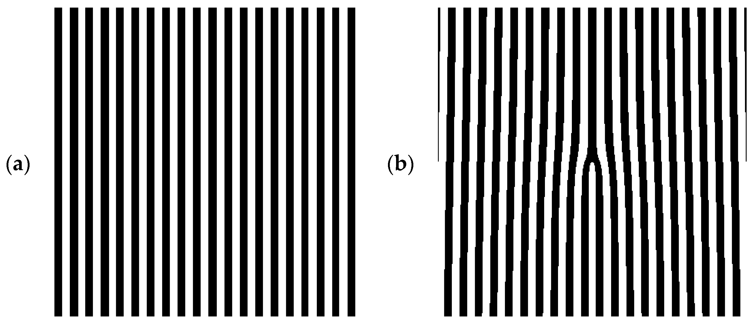
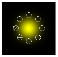
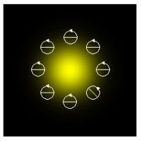
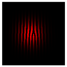
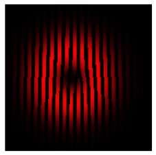
In the simulation, it is assumed that the LG beam illuminates a conventional or fork amplitude binary grating (
Figure 2) and is focused. In the calculations using formula (2), the laser radiation is set to be the LG beam at
m = 0 and
m = 1 with a radius of σ = 25 μm and a wavelength of λ = 1 μm, and the gratings have a size of 100 μm × 100 μm with a period of 5 μm.
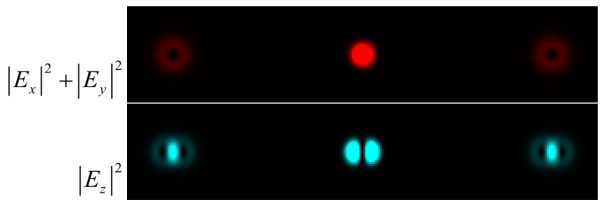
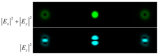
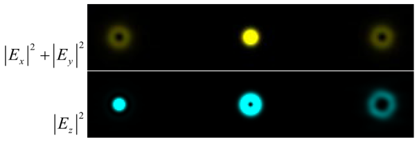
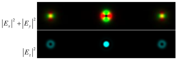
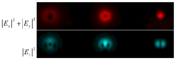
The simulation results for a conventional grating are shown in
Table 1 and
Table 2 for different beam types and polarization states. The tables show the focusing results for a numerical aperture close to the limiting NA = 0.99 (focal length f = 101 μm). In this case, the intensity of the longitudinal component of the focused field
makes a significant contribution to the total field intensity. This property is useful for focal spot size reduction [
69,
70,
71,
72,
73], laser material processing, and surface structuring [
74,
75,
76,
77]. Therefore,
Table 1,
Table 2,
Table 3 and
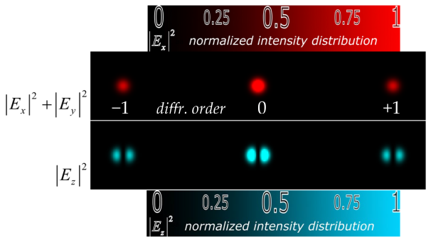
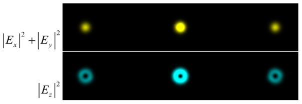
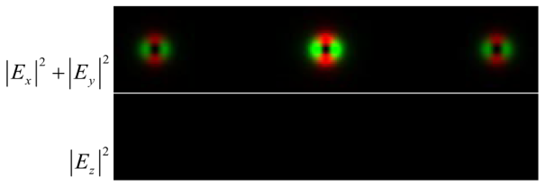
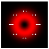
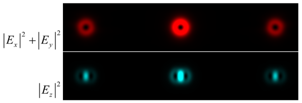
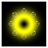
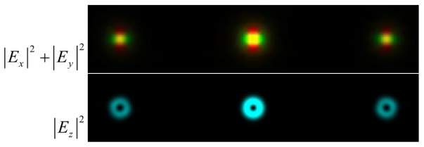
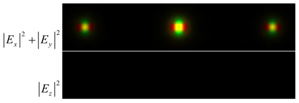
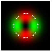
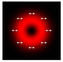
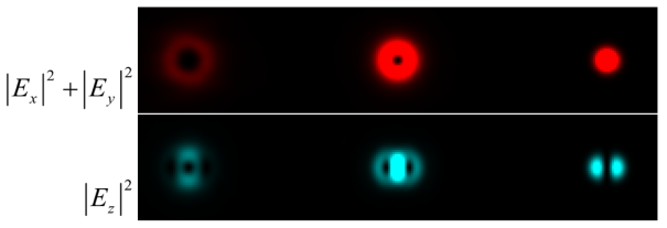
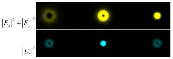
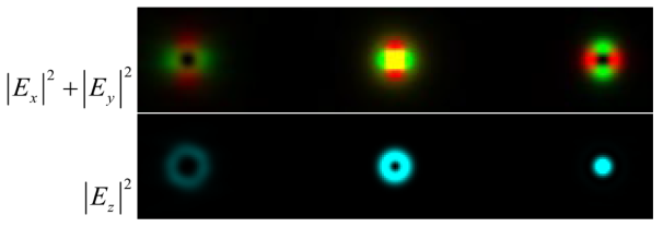
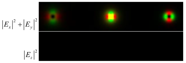
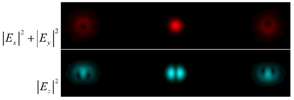
Table 4 separately show the normalized intensity distribution for the first three diffraction orders: −1 (on the left), 0 (at the center), +1 (on the right) of the transverse components
(with red color scale for
and green for
with color sum to yellow color) and the longitudinal component
(with blue color scale).
We only show the intensity patterns of the transverse and longitudinal components of the electric field to visualize the polarization transformation. In practice, it is usually difficult to reconstruct the phase distribution; however, the change in the intensity structure in each diffraction order shows the mode transformation, and can also indirectly indicate the phase structure.
As can be seen from the results given in
Table 1 and
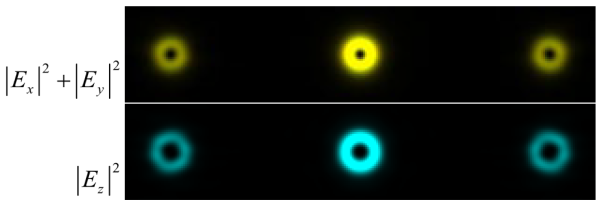
Table 2, when using a conventional grating, the usual replication of the incident beam occurs. However, circular polarization of different directions (
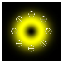
Table 1, rows 3, 4) leads to the formation of vortex beams of different signs in the longitudinal component [
78,
79], namely, exp(
iϕ) for circular “+” polarization and exp(−
iϕ) for circular “−” polarization. Note that a combination of components of “+” and “−” circular polarization corresponds to X-linear polarization:
. This fact is easily seen for intensity distributions of transverse components
(compare row 1 with rows 3 and 4 in
Table 1,
Table 2,
Table 3 and
Table 4). For longitudinal components
, this is not so evident, because one should take into account the phase state of focused beams. In particular, for
Table 1, we obtain sum of opposite vortices: 0.5[exp(
iϕ) + exp(−
iϕ)] = cos(ϕ), which corresponds to two horizontal light spots, as observed in the calculations (
Table 1, row 1).
For the longitudinal component
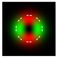
, a spin–orbit transformation is observed for a first-order vortex beam (m = 1) with circular “−” polarization (
Table 2, row 4). This fact was also noted in previous publications [
78,
79,
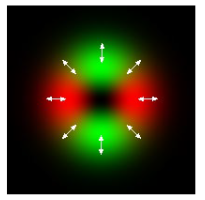
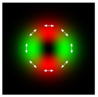
80]. In addition, the transformation of cylindrically polarized beams into an orthogonal state can be seen (
Table 2, rows 5 and 6). Thus, the initially radially polarized vortex beam in the focal plane becomes azimuthally polarized and vice versa. A detailed discussion of this effect can be found in the article [
81].
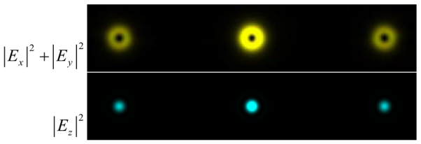
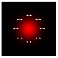
It is worth noting that, in the case of tight focusing of a Gaussian beam with a radial polarization state (
Table 1, row 5), the intensity of the longitudinal component of the focused field
, which has a compact light spot, makes a significant contribution to the total field intensity. A similar situation occurs when illuminating with an LG beam at
m = 1 with a circular “−” polarization state (
Table 2, row 4). The intensity of the longitudinal component
ensures a decrease in the size of the focal spot of the formed beam in each of the −1, 0, and +1 diffraction orders.
The simulation results for the fork grating for different beam types and polarization states are shown in
Table 3 and
Table 4. In this case, more complex transformations occur. When illuminated by a Gaussian beam (
Table 3), the original beam state is preserved only in the zero diffraction order.
The transverse intensity distribution
shows the generation of vortex beams (light rings) in diffraction orders 1 and −1 (
Table 3, rows 1–4). However, the fact that these vortex beams are of opposite signs is confirmed just from the intensity distribution of the longitudinal component
with circular polarization (
Table 3, rows 3 and 4) due to spin–orbit transformation [
78,
79,
80]. It is seen that, when the polarization direction changes, the annular distribution and the light peak swap.
So,
Table 3 clearly shows the formation of ±1 vortex beams in ±1 diffraction orders. Depending on the polarization state of the original Gaussian beam, the distribution of the focused field in different diffraction orders can change. When a binary fork grating is illuminated by a Gaussian beam with circular polarization “+” (
Table 3, row 3), a compact light spot in the diffraction order +1 is formed in the longitudinal component of the field. If the polarization sign is changed to the opposite (
Table 3, row 4), the situation described above will be observed in the −1 diffraction order. This is a result of the spin–orbit interaction at tight focusing [
78,
79,
80]. For cylindrical polarization types (
Table 3, rows 5 and 6), the introduction of a vortex-like phase singularity leads to compensation of the annular structure of the transverse components in ±1 diffraction orders regardless of the sign.
When a vortex beam illuminates a fork grating, the transformations become even more complex (
Table 4). The complexity of the transformation, in this case, is because the vortex beams formed by the fork grating in diffraction orders 1 and −1 have opposite signs. Therefore, when illuminated by a vortex beam, in one order the vortex-like phase singularity is compensated, and in the other, the vortex order is increased. This is seen from the intensity distributions of the transverse components
(
Table 4, rows 1–4). The corresponding transformations also occur in the distributions of the longitudinal components
. In cylindrical types of polarization, the initial beam is formed in −1 order (
Table 4, rows 5 and 6), and orthogonal polarization transformations occur in the 0 and +1 orders. Moreover, in the −1 diffraction order, a cylindrical polarization of a higher order is formed [
52,
81].
The polarization and mode transformations shown in this section are possible not only with tight focusing but also in near-field diffraction. In the next section, this situation is considered in detail based on the FDTD method, considering the 3D structure of the gratings.
4. Numerical Analysis in the Near-Field Diffraction
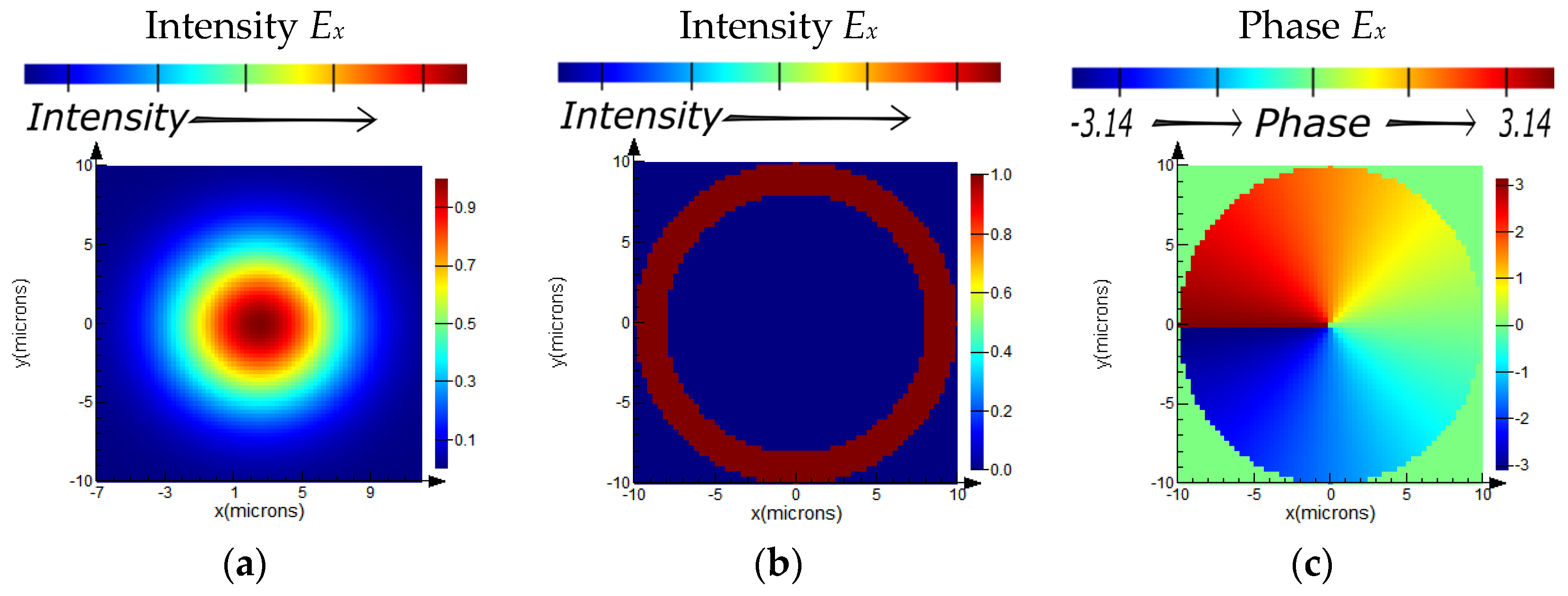
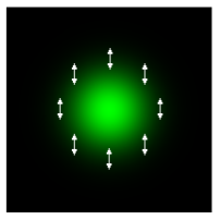
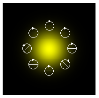
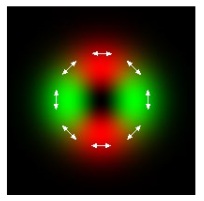
The laser radiation is a beam with an aperture radius of 20 μm and a wavelength of λ = 1.5 μm. Various types of polarization and configuration (cross-section) of the beam are considered (
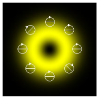
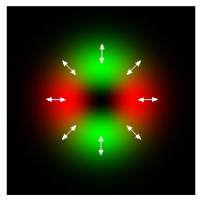
Figure 3):
Gaussian beam with a waist radius of 10 µm.
Uniform linear X and Y polarization;
Uniform circular polarization;
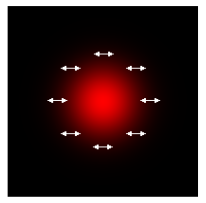
Non-uniform radial and azimuthal polarizations.
A plane X-polarized wave limited by an annular aperture with an inner radius R1 = 8 µm and an outer radius R1 = 10 µm.
Vortex X-polarized beam with topological charge q = 1 (first-order vortex).
Here, and in the following figures and tables, the color scale corresponds to the value of intensity and phase.
The optical element based on polyester carbonate (PEC) is specified as an amplitude binary grating (6) with the parameter values
d = 3.2 μm,
b = 1.6 μm, and the fork grating (10) with the parameter values
d = 3.2 μm;
m = 1; 2 and 3. The total size of the grating of the first and second types is 20 μm × 20 μm × 3 μm (
Figure 4).
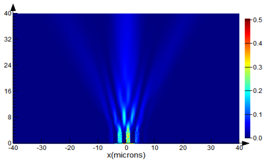
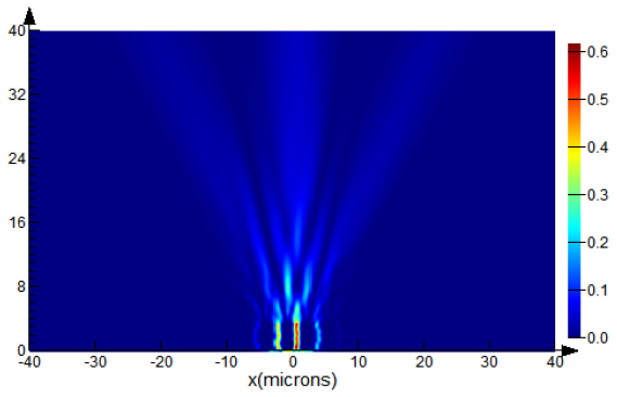
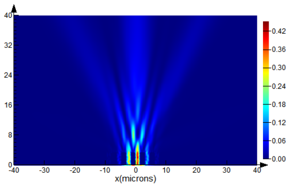
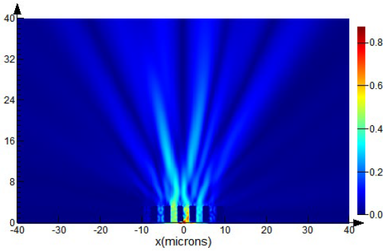
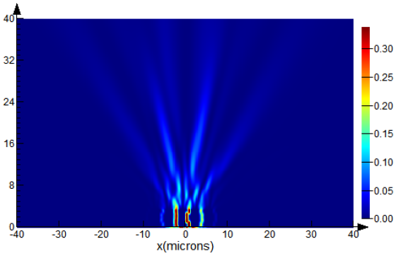
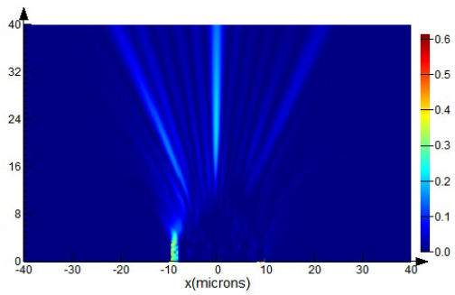
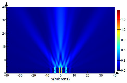
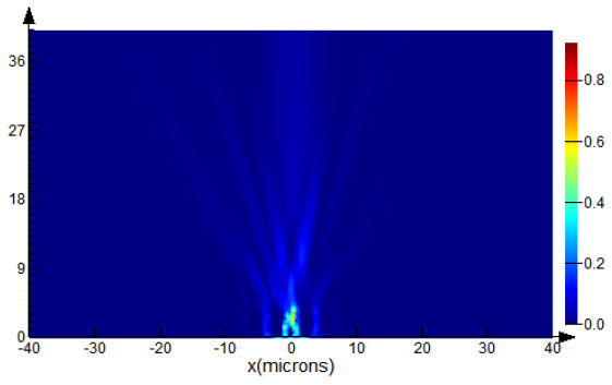
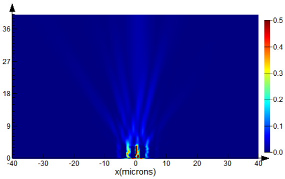
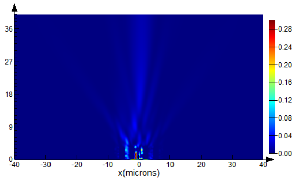
A parallelepiped measuring 80 μm × 20 μm × 40 μm (
Figure 5) with a simulation time of 1000 fs was selected as the computational domain for the FDTD method realized in Lumerical software. The calculation is performed with an irregular step, the minimum value of which is 0.00025 μm in spatial coordinates and 0.29 fs in the time domain. We applied perfectly matched layer (PML) boundaries to implement as an absorbing material to minimize reflections. By increasing the computational domain and the source distance from the grating, we also verified that these factors do not affect the distribution of intensity and phase.
4.1. Diffraction on the Amplitude Binary Grating
Let us calculate the diffraction of a differently polarized Gaussian beam with an aperture radius of 20 μm, a waist radius of 10 μm, and a wavelength of λ = 1.5 μm on the amplitude binary grating (6) with parameter values
d = 3.2 μm,
b = 1.6 μm (
Figure 2a).
- a.
Gaussian beam with uniform polarization
Table 5 shows the distributions of the intensity and phase of the E
x component of the electric field vector E after passing through the amplitude binary grating of X-polarized laser radiation at a distance of
z = 40 μm.
Using X-polarized laser radiation as a source in a numerical experiment based on the FDTD method, an intensity distribution corresponding to three diffraction orders was obtained. Moreover, the maximum intensity was observed in the central p = 0 order, and a uniform energy distribution was approximately 33% of the maximum in p = ±1 orders. The diffraction pattern obtained in the numerical experiment is consistent with the calculation results in the previous section.
Further studies were conducted on the influence of uniform (linear Y and circular) and non-uniform (radial and azimuthal) polarization on the beam structure and energy distribution in its cross-section.
Table 6 presents the results of the numerical simulation of Y-polarized laser radiation propagation through the amplitude binary grating. Similar to X-polarized laser radiation, the intensity distribution corresponds to three diffraction orders. Moreover, the energy is distributed as follows: the maximum (80% of the maximum in the
z = 40 μm plane when using X-polarized laser radiation) is still detected in the central
p = 0 order, but the uniform energy distribution in
p = ±1 orders corresponds to approximately 55% of the maximum, which is 1.7 times greater than in the previous numerical experiment (
Table 5). The diffraction pattern obtained in the numerical experiment, considering the 3D structure of the grating, is in qualitative agreement with the calculation results in the previous section.
Table 7 presents the case of circularly polarized laser radiation propagating through an amplitude binary grating. The transverse intensity distribution aligns with the two previous experiments. The energy in the central
p = 0 order is maximal (90% of the maximum in the
z = 40 μm plane when using X-polarized laser radiation), and the uniform energy distribution in
p = ±1 orders corresponds to approximately 50% of the maximum, which is equivalent to the result of the previous numerical experiment (
Table 6).
The calculated diffraction pattern qualitatively agrees with the calculation results in the previous section. Note that the formation of compact light spots is observed in the near-field diffraction when using other elements of micro-optics, namely generalized spiral phase plates [
82] and diffractive axicons [
83].
It should be noted that the maximum intensity of the central order is observed with an X-polarized beam, which is explained by the co-direction of the x-component of the electric field vector of the source and the microrelief of the diffraction grating.
The energy distribution in p = ±1 orders when using laser radiation with circular polarization is particularly interesting. In this case, the energy is 50% of the maximum, which in turn is equal to 90% of the maximum energy in the same plane when using an X-polarized source. Thus, changing the type of uniform polarization allows for the controlled redistribution of energy between diffraction orders.
Note that the amplitude binary grating only replicates the incident beam, maintaining the polarization state.
- b.
Gaussian beam with nonuniform polarization
Additionally, in a numerical experiment based on the FDTD method, the diffraction of non-uniform radially and azimuthally polarized laser radiation on an amplitude binary grating is calculated. The transverse intensity distribution of the radially and azimuthally polarized beam has an annular structure in full accordance with the results of the previous section.
Table 8 shows the obtained intensity and phase distribution of the electric field vector components at a distance
z = 40 μm from the radially polarized source after passing through the amplitude binary grating. Based on the resulting intensity distribution E, it can be concluded that the practically annular structure of the formed beam is observed in all diffraction orders. Errors in the intensity distribution are associated with the 3D structure of the grating and some overlap of the diffraction orders. The maximum intensity is observed on the annular beam in the
p = 0 order, and the unevenly distributed energy is detected inside these beams in the
p = ±1 orders.
Table 9 considers the case of propagation of azimuthal polarized laser radiation through an amplitude binary grating. The obtained distribution of the total intensity is similar to the distribution when using a radially polarized source. In this case, the intensity of the longitudinal component is small (its presence is associated with the near-field diffraction), so the intensity distribution is completely determined by the transverse components of the electric field.
- c.
Vortex beam with uniform linear polarization
Let us calculate the diffraction of a vortex X-polarized beam with a topological charge
q = 1 (a first-order vortex) on an amplitude binary grating to demonstrate the replication of a vortex beam in different diffraction orders.
Table 10 shows the calculation results. According to the transverse intensity distribution of the Ex component of the electric field vector E, three sophisticated annular distributions can be observed in the
p = 0 and
p = ±1 diffraction orders. The most informative is the phase of the x-component Ex of the electric field vector E. The first-order vortex phase is detected in the
p = 0 diffraction order. In the
p = ±1 diffraction orders, fork-shaped phase distributions are observed, associated with an additional linear phase incursion in non-zero orders [
19,
32,
33]. It is known [
84,
85] that
p = ±1 orders have a phase shift of π/2 from the zero order. In addition, positive and negative diffraction orders have a phase shift of π from each other, which can be visually observed when non-axially symmetric beams are formed by binary gratings [
86,
87] since the beams rotate in different directions or the intensity distributions are mirrored. In the case of a vortex beam, a phase rotation of 180 degrees occurs [
55], which is observed in the rotation of the fork-shaped phase structure in
Table 10.
This means that the binary grating not only replicates the incident beam but also introduces a phase shift in non-zero diffraction orders.
The redistribution of energy between diffraction orders occurs similarly to a Gaussian beam with x-polarization: the maximum intensity is observed in the central p = 0 order, and the uniform distribution of energy is approximately 30–40% of the maximum in the p = ±1 orders.
- d.
Annular beam with uniform linear polarization
This section considers the calculation of the diffraction of an X-polarized annular beam on the amplitude binary grating to form a beam with a smaller radius in each of the diffraction orders.
Table 11 represents the case of propagation of a beam with X polarization and annular intensity distribution through an amplitude binary grating. Three beams in
p = 0 and
p = ±1 diffraction orders can be observed from the transverse intensity distribution of the Ex component of the electric field vector E. The maximum intensity is observed in the central
p = 0 order, and the uniform energy distribution is approximately 40–45% of the maximum in the
p = ±1 orders. It is worth noting that the radius of the formed beam at a fixed distance z = 40 μm is two times smaller compared to a case of using a Gaussian beam light source (
Table 5). It is difficult to draw clear conclusions from the phase of the x-component Ex of the electric field vector E. In the
p = 0 diffraction order, a phase similar to that obtained using an X-polarized Gaussian beam is detected (
Table 5). In the
p = ±1 diffraction orders, a complexly organized change in the phase distribution is observed.
4.2. Diffraction on an Amplitude Binary Fork Grating
In this section, the diffraction of an X-polarized Gaussian beam on an amplitude binary fork grating for a vortex beam formation with a given topological charge in nonzero diffraction orders is considered. To control the topological charge of the beam, it is proposed to vary the parameter
m in formula (10), which is responsible for the vortex component of the complex transmission function of the grating. It is known [
33] that mathematical simulation in the scalar approximation describes the dependence of the topological charge of the formed beam on the parameter
m of the complex transmission function of the grating (10) in the form of a direct linear dependence.
Table 12 shows the vector calculation based on the FDTD method. The parameter
m varies in the range from 1 to 3 with a step of 1, which corresponds to the topological charge of the formed beam from 1 to 3, respectively.
At
m = 1, based on the transverse distribution of the intensity
Ex component of the electric field vector
E, it can be concluded that, in the central order
p = 0, a Gaussian beam is formed with a radius corresponding to the radius of the beam in
Table 5 (
z = 40 μm, diffraction of a Gaussian beam on an amplitude binary grating), with maximum energy in the plane
z = 40 μm equal to 3% of the maximum in the same plane when using an amplitude binary grating. However, in
p = ±1 orders, annular beams with uniformly distributed energy of approximately 35–40% of the maximum are observed.
The following conclusions can be drawn from the phase of the
x-component
Ex of the electric field vector
E: in the
p = 0 diffraction order, a phase similar to that obtained using an X-polarized Gaussian beam is detected (
Table 5), i.e., the original Gaussian beam is preserved; in
p = ±1 diffraction orders, a vortex phase distribution with a topological charge equal to 1 is observed, similar to that obtained during the propagation of first-order vortex laser radiation with X polarization through an amplitude binary grating (
Table 10) with an accuracy of up to the sign of the topological charge. The diffraction pattern obtained in the numerical experiment is in complete agreement with the calculation results in the previous section.
At m = 2 and m = 3, based on the transverse distribution of the intensity of component Ex of the electric field vector E, it can be concluded that the Gaussian beam is preserved in the p = 0 diffraction order. However, in p = ±1 orders, beams with an open annular structure are observed, amounting to approximately 35–40% of the maximum.
From the phase of the x-component Ex of the electric field vector E, the following conclusions can be drawn: in the p = 0 diffraction order, the phase remains flat; and in the diffraction orders p = ±1, a vortex phase with a topological charge equal to m is observed (the number of fork “legs” is 1).
The results of the calculation of the diffraction of a circularly polarized Gaussian beam on a binary fork grating are shown in
Table 13. In the transverse components
Ex and
Ey of the electric field vector, an annular intensity distribution is formed in ±1 orders of magnitude with a topological charge corresponding to the parameter
m in formula (10), which is responsible for the vortex component of the complex transmission function of the grating. In the longitudinal component Ez, a more complex picture is observed due to the spin–orbit transformation [
78,
79,
80]. It is evident that a compact light spot is formed in the +1st diffraction order, an annular distribution with a vortex phase in the 0th order, and fragments of an annular distribution with a fork phase in the –1st order.
As in the case of a conventional diffraction grating, the calculated diffraction pattern is in qualitative agreement with the calculation results in the previous section, but the intensity distribution of the longitudinal Ez component of the electric field differs slightly from that obtained in the focal plane in the thin element approximation in the previous section.
Below, the calculations of the diffraction of a circularly polarized Gaussian beam on a binary fork grating at
m = 2 and
m = 3 are considered.
Table 14 shows the intensity and phase distribution of the transverse
Ex component of the electric field vector. It is shown that vortex beams with different topological charges are formed in ±1 orders.
At m = 2 and m = 3, from the transverse distribution of the intensity Ex of the electric field vector component, it can be concluded that the Gaussian beam is preserved in the p = 0 order. However, beams with an opened annular structure are observed at p = ±1 orders.
Based on the phase of the x-component Ex of the electric field vector E, the following conclusions can be drawn: in the central p = 0 diffraction order, the phase remains flat, and in the p = ±1 diffraction orders, a vortex phase with different topological charges is observed.
In addition, we will calculate the diffraction of the first-order Laguerre–Gaussian vortex beam with X polarization on a binary fork-shaped grating at
m = 1. The calculation results are given in
Table 15 and completely confirm the results obtained in the previous section, demonstrating the formation of vortex beams with different rotation directions by a fork-shaped grating in ±1 diffraction orders. In this case, the incident beam with a vortex phase singularity leads to compensation of the vortex beam in the −1 diffraction order (a conventional Gaussian beam is formed), the incident beam, i.e., the first-order vortex, is preserved in the central order, and a second-order vortex arises in the +1 diffraction order.
5. Discussion
A comparative analysis of the results of diffraction calculations on a flat optical element in the focal plane and on an optical element with a significant 3D structure in the near field (at a distance of about ten wavelengths) opens a discussion about the possibilities that arise due to microstructures and microelements with unusual morphology for polarization-mode transformation of the light field.
The polarization-mode composition of the incident radiation plays an important role in the formation of structured light. The formation of such laser radiation structured by several parameters can be performed using 3D microstructures. The demonstrated composite fork microgratings allow for the creation of a set of vortex beams with different values of topological charge that can be used for the orbital angular momentum sensing. The study of conventional binary microgratings with a significant 3D structure confirms the possibility of replicating the incident beam in near-field diffraction [
82,
88,
89,
90,
91], similar to the elements of flat optics. In [
88], diffraction on a subwavelength aperture and a grating is considered. In works [
83,
89,
90], binary axicons and a zone plate (a binary analog of a microlens) with a high numerical aperture are used for tight focusing of laser radiation in the near-field diffraction; in work [
91], a twisted conic micro-axicon is also considered, which ensures the formation of spiral intensity.
Thus, taking into account the 3D essence of the microstructure leads to a distortion (
Table 16, row 2, zero diffraction order) of the beam structure and a break (
Table 16, row 2, ±1 diffraction orders (dashed line)) of the annular intensity only during the diffraction of the first-order vortex beam on the amplitude binary grating. However, the general stability of the singular beam structure is preserved.
It should be noted that vortex beams are quite sensitive to various deviations in focusing optical systems, such as a tilt, displacement from the optical axis, or the presence of other aberrations [
92,
93]. The same applies to the situation of non-coaxial illumination of the fork-shaped grating. However, as was shown in the paper [
94], the off-axis shifted optical vortex of an arbitrary order is equivalent to the finite sum of the on-axis vortices of lower orders. So, for the vortex singular phase or the fork-shaped grating of the first order (the actual situation), the distortion in polarization and mode states will be minimal. Numerical calculations (
Table 17) show that horizontally shifting the illuminating Gaussian beam by one grating period (5 μm) does not affect the polarization transformations in any way; only a slight distortion of the intensity distribution in the components of the focused field is observed.
The results of calculating the diffraction in the near zone on a fork grating are similar. It is evident (
Table 18) that, when the source is shifted by 2.5 μm (which corresponds to 25% of the element radius) relative to the center of the element, the annular intensity distributions in ±1 diffraction orders are somewhat distorted (in the form of a crescent), but the vortex phase is preserved. There is also no effect of shifting on the polarization transformation. It is also evident that the co-axial results correspond to those in
Table 16 (third row). We study the tolerance for misalignment of the illuminating beam and the spiral phase plate using the FDTD method in [
81]. In this work, it was shown that the vortex phase retains its structure even when the incident beam is shifted by a distance greater than half the element radius.
Increasing the overall size of the grating, as a rule, leads to a clearer formation of the diffraction pattern, but this will require broadening the illuminating beam in practice.
Another factor influencing the distribution in the focal plane is the grating period, which usually leads to a change in the distance between diffraction orders.
The grating equation is well known:
where
p is the index of the diffraction order, λ is the wavelength of light, θ is the angle of light incidence, and θ
p are the angles for diffraction orders.
For normal incidence θ = 0 and for the first-order
p = 1 instead of (15), we obtain:
As follows from (16), for a fixed wavelength of the illuminating beam λ, the first-order position shifts further from the center as the period
d decreases down to a value equal to the wavelength λ. As the period decreases to less than the wavelength, only the zero order remains, and the grating becomes subwavelength with anisotropic polarization properties and can be used as a metasurface for polarization transformation [
95,
96]. We do not consider the case when
d ≤ λ in this paper. Thus, changing the period value within the condition
d > λ will only lead to a change in the distance between the diffraction orders.
Recently the action of anisotropic polarization gratings has attracted increasing attention from researchers, since in this case a more complex and selective interaction with the illuminating beam is ensured [
97,
98].
6. Conclusions
In this paper, the analysis of polarization-mode transformations of the light field during diffraction on two types of amplitude binary gratings was performed. The simulation of two (conventional and fork-shaped) types of amplitude binary gratings was performed in the focal plane based on the Richards–Wolf formalism, as well as in the near-field diffraction based on the FDTD method taking into account the 3D structure of optical elements.
It was shown that, although the conventional binary diffraction grating only performs the replication of the incident beam, in tight focus conditions (when the additional tight-focusing lens is used) the polarization transformation occurs due to part of the energy being transferred to the longitudinal component of the electric field.
The significantly more sophisticated picture is observed in the case of diffraction on fork-shaped grating due to the formation of vortex beams of various directions in ±1 diffraction orders. Depending on the phase singularity presence and the incident beam polarization state, various phase and polarization transformations occur in different components of the electric field.
Similar effects were seen in the near-field diffraction on the considered diffraction gratings concerning their 3D structure using the FDTD method. The results are slightly different, although a qualitative agreement of computational results is observed.
The obtained results can be used in the field of laser material processing and surface structuring [
74,
75,
76,
77], including the potential use of the proposed theory in transient gratings induced by high-irradiance beams in applications such as morphological modification conducted by pulsed laser ablation [
99]. It is worth noting that the dispersion characteristics of the amplitude elements ensure the independence of the wavelength for short pulses. In addition, fork-shaped gratings are promising in problems of mode and/or polarization state detection [
7,
33] when diffraction efficiency is not a crucial factor. The results obtained in the near diffraction zone are also relevant in connection with the miniaturization of measuring, detecting, or switching optical devices [
100,
101,
102].

